Advertisement
Advertisement
Table of Contents

Subscribe to Our Youtube Channel
Related Manuals for Vimar ELVOX 40505


Summary of Contents for Vimar ELVOX 40505
- Page 1 Installer manual 40505 Tab 7 Due Fili Plus hands-free video entryphone...
- Page 2 The instructions manual can be downloaded from the website www.vimar.com INSTALLATION RULES Installation must be carried out in compliance with the current regulations regarding the installation of electrical equipment in the country where the products are installed.
-
Page 3: Technical Characteristics
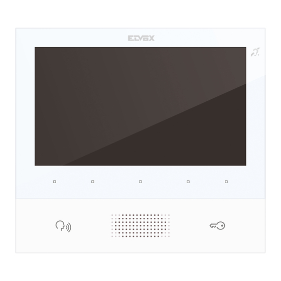
Can be used by wearers of hearing aids. Technical characteristics • Wall-mounted, with metal bracket, in box: circular 2M (Vimar V71701), 3M (Vimar V71303, V71703) hori- zontal and vertical, 4+4M (Vimar V71318, V71718) and square, British standard. • 7" LCD 16:9 display, resolution 800x480 pixels •... -
Page 4: Installation
Note: Fig. 1 shows the recommended installation distances, unless otherwise specified by current regula- tions. 1. Secure the plate to the wall, with metal bracket, in box: circular 2M (Vimar V71701), 3M (Vimar V71303, V71703) horizontal and vertical, 4+4M (Vimar V71318, V71718) and square, British standard. - Page 5 TAB: 40505 Fig. 2 Fig. 3...
- Page 6 TAB: 40505 Connections On the rear there is a terminal board for: • Connection of the Due Fili Plus bus • The Landing Call input. The maximum connection distance is 10 m. When suitably programmed using SaveProg, this input can be used for the Alert function. See the relative paragraph. Connection terminal block Terminals Function...
- Page 7 TAB: 40505 Video Termination Select DIP switch to terminate the video signal A) if the BUS cable enters terminals 1, 2 and continues to another internal unit. B) when a BUS cable with a characteristic impedance of 100 Ohms (Elvox 732I or 732H cable) enters ter- minals 1, 2 and the riser stops in the internal unit C) when a BUS cable with characteristic impedance of 50 Ohms (Cat.
- Page 8 TAB: 40505 Connecting the internal unit art. 40505 in the in/out configuration In/out wiring diagram 50Ω 100Ω Termination to apply OPEN Cable riser Connecting the internal unit art. 40505 in terminal configuration Wiring diagram with cable terminating in the internal unit Cable riser Termination to be applied depending on the characteristic impedance of the cable 50Ω...
-
Page 9: Key Functions
TAB: 40505 Key functions In the subsequent sections of this document the touch keys are designated as shown in the figure below: M (ACCESS CONFIGURATION) T2 (STAIR LIGHT) T3 (F1) T1 (SELF-START) T4 (USER ABSENT / MUTE MICROPHONE) P/A (ANSWER / END DOOR LOCK CONVERSATION) Keys T1..T4 have two operating contexts:... -
Page 10: First Power Up
TAB: 40505 First power up The 40505 leaves the factory without an ID, as do all other internal units (except kits). On switching on the display by touching the keypad, the only action possible is to assign main or secondary internal unit as the ID: First power up On choosing one of the two, the internal unit requests ID assignment from the Master external unit and the... - Page 11 TAB: 40505 Assigning ID...
- Page 12 TAB: 40505 After ID assignment Once the ID has been assigned, the display, when woken up, appears as follows: Main screen The P/A key toggles between the context displayed (Operators) and Intercom: Intercom context If the P/A key is touched when the internal unit is in standby mode, the unit will wake up in the Intercom con- text.
-
Page 13: User Configuration
TAB: 40505 User configuration Touching the M key while in the Operators context opens the user configuration menu. In all the menus, naviga- tion is circular, i.e. scrolling down past the last option in any menu takes you back to the first option. User configuration menu T1 returns you to the Operators context, while T4takes you to the highlighted configuration option. -
Page 14: Ringer Mute
TAB: 40505 Ringer mute to enable/disable the ringer of the internal unit, for calls from PE, as follows: • : (ringer enabled) • : (ringer disabled) The internal unit does not ring, but otherwise functions normally. • : (user absent) The internal unit does not ring and does not switch on. With configuration via SaveProg (flag 22 ACK. - Page 15 TAB: 40505 Select melody for calls from external unit to select one of the 10 available melodies (identified by letters A to J) to use as a ringtone for calls from the external unit. The internal unit plays back the selected ringtone. Default: melody B.
- Page 16 TAB: 40505 Select melody for calls from landing to select one of the 10 available melodies (identified by letters A to J) to use as a ringtone for calls from the landing. The internal unit plays back the selected ringtone. Default: melody C.
- Page 17 TAB: 40505 Select melody for calls from internal unit or switchboard to select one of the 10 available melodies (identified by letters A to J) to use as a ringtone for calls from an internal unit or switchboard. The internal unit plays back the selected ringtone. Default: melody D.
-
Page 18: Ringer Volume Control
TAB: 40505 Ringer volume control to increase/decrease the ringer volume, which is indicated by the horizontal bar. NOTE: the level set is used for all ringtone types (calls from the external unit, landing, internal unit or switchboard). Default: level 5. Select ringer volume control Ringer volume control... -
Page 19: Brightness Control
TAB: 40505 Brightness control to increase / decrease the brightness of the video signal from an external unit, the level of which is indicated by the horizontal bar. The internal unit automatically requests the Master external unit to perform a self-start procedure so that the user can see the effect of the brightness control. -
Page 20: Contrast Control
TAB: 40505 Contrast control to increase / decrease the contrast of the video signal from an external unit, which is indicated by the horizontal bar. The internal unit automatically requests the Master external unit to perform a self-start procedure so that the user can see the effect of the contrast control. NOTE: the level set is used for all external units. -
Page 21: Key Tones
TAB: 40505 Key tones Use the keys to enable/disable the tone produced whenever a key is touched (keystroke feedback). Default: enabled Key tone Key tone... - Page 22 TAB: 40505 Keypad cleaning Activates the keypad cleaning function: Keypad cleaning activation The keypad cleaning procedure lasts 20 seconds and this time period cannot be extended by pressing the keys, which remain disabled until the keypad cleaning procedure is completed.
- Page 23 TAB: 40505 Installer configuration To access the installer menu , you must enter the 3-digit code (PIN). The default PIN is 000, but this can be changed as described below. The PIN is entered using the following keys: • to cancel the last digit, provided that the cursor is on the second or third digit, otherwise use to return to the user configuration menu.
- Page 24 TAB: 40505 Entering the PIN Entering the PIN Installer menu...
- Page 25 TAB: 40505 Selection of key icons in the Operators context With the option you can change the icons that appear above the keys in the Operators context. The default setting is blank: Selection of key icons in the Operators context Which means that the preset icons i.e., those which first appear, will be used.
- Page 26 TAB: 40505 Selection of key icons If an icon has already been assigned, an option will be added to the specific menu that allows you to cancel the assigned icon and replace it with the default icon. Selection of key icons This operation must be confirmed:...
- Page 27 TAB: 40505 Confirm icon cancellation To change an icon, you do not need to cancel it first, just simply replace it with a new icon.
- Page 28 TAB: 40505 Intercom With the option you can change the IDs of internal units or porter switchboards to be used in the Inter- com context. The default setting is blank: Intercom menu Each line corresponds to one of the four keys in the Intercom context. On selecting one of these four options, a sub menu opens: Selection of intercom type The three options that appear are:...
- Page 29 TAB: 40505 • to cancel the association with the selected position (visible only if the position is programmed). Association of an internal unit Selection of intercom type In this condition, on the internal unit that is to be called, press a key that can be identified unequivocally. It is advisable to use a key that controls opening of a lock, but you can also use a key that operates a relay or controls one of the F1 or F2 outputs of an external unit.
- Page 30 TAB: 40505 Selection of the switchboard to be called Select the porter switchboard you wish to assign to the previously selected key in the Intercom context and confirm. The basic menu of Intercom context will appear as follows: Selection of the switchboard to be called Association of the Alert function On confirming the function, the Alert function is immediately assigned to the previously selected key in the Intercom context:...
- Page 31 TAB: 40505 Cancelling an association Awaiting confirmation of intercom cancellation Confirm or cancel removal of the association between previously selected key in the Intercom context.
-
Page 32: Changing The Pin
TAB: 40505 Assignment of main and secondary ID For descriptions of these procedures, refer to the beginning of the paragraph First power up. Changing the PIN To change the PIN, follow the same procedure as that used to enter it to access the installer configuration menu. The following example shows how to set the PIN to 123: Touch Touch... - Page 33 TAB: 40505 Touch Touch 3 times Touch The PIN has now been changed to 123.
- Page 34 TAB: 40505 Reset factory configuration This procedure allows you to cancel any settings and programming of the internal unit and to restore it to the original default condition. The system asks for confirmation that you wish to proceed with the reset: Selection of Reset factory configuration Awaiting confirmation of Reset factory configuration From this moment, the internal unit is in the First power up condition.
-
Page 35: System Information
TAB: 40505 System information From this menu, useful information can be obtained for Vimar customer service (SAC / TSX), including ID, Firmware version, etc.: System information Information display • The information reported, from the top downwards, is as follows: •... - Page 36 TAB: 40505 Programming with SaveProg The correspondence between the SaveProg manages Art. 40505 from version 3.3.2.1 onwards. keys P1..P8 of SaveProg and the keys T1..T4 in the two operating contexts is as follows: OPERATORS INTERCOM The LOCK key corresponds to P0.
- Page 37 TAB: 40505 Call to internal unit (outgoing) Note: before connecting the audio channels with any other device, the internal unit Art. 40505 determines the best possible communication parameters. During this stage, which lasts approximately 1 second, a waiting tone is transmitted to the user. To make a call to another internal unit, at least one call must be programmed as described above.
- Page 38 TAB: 40505 The icons at the top left of the display indicate that a call is being made to the internal unit programmed as T1. While waiting for an answer, you can press T2 and T3. On receiving an answer, the display changes to: The centre key, now , and T4 are enabled.
- Page 39 TAB: 40505 The T1 and T2 keys turn grey respectively when the minimum and maximum levels are reached. The centre key, now , allows you to return to the previous context. The conversation can be ended with the P/A key or by the internal unit to which the call was made using the appropriate procedure.
- Page 40 TAB: 40505 Call from internal unit (incoming) On receiving a call from another internal unit, the display appears like this: Incoming call from internal unit The number at the top left indicates the position of the caller in the list of keys in the Intercom context. If the caller is not present in the list, no number will be displayed.
- Page 41 TAB: 40505 Call from switchboard 1 For incoming intercom calls, it is not possible to mute the ringer before a call is received. It is only possible to mute the ringer for the current call. Once muted, the ringer cannot be switched back on during the current call, so the icon disappears.
- Page 42 TAB: 40505 Switchboard scenarios If the unit either making or receiving the call is a porter switchboard, there are other possible scenarios. For example, the switchboard operator could connect an internal unit to another internal unit, to an external unit or to a second porter switchboard.
- Page 43 TAB: 40505 to re-enable the microphone. Alternatively, you can also use T4 before the new connection is made. In this case the microphone will already be enabled. Given that it is not possible to know beforehand the exact moment at which the switchboard operator will connect the internal unit to the other party, this strategy has been chosen in order to ensure that the other party hears nothing unless at the explicit request of the party waiting.
- Page 44 TAB: 40505 Call from external unit (incoming) On receipt of a call from an external unit, the display can appear in two different ways, depending on whether the call is coming from an audio only or from an audio/video external unit: Call from external unit (incoming), Audio Call from external unit (incoming), Video Note: the display of internal unit Art.
- Page 45 TAB: 40505 CALL FROM VIDEO EXTERNAL UNIT FLAG 1 (MONITOR ON) RESULT ACTIVE Switches on Direct NOT ACTIVE Does not switch on ACTIVE Switches on Indirect (belongs to a group with only one secondary unit) NOT ACTIVE Does not switch on ACTIVE Does not switch on Indirect (belongs to a group with at least two...
- Page 46 TAB: 40505 Answering an audio call Answering a video call As in a conversation with an internal unit, T4 has the function of muting or re-enabling the microphone. After answering, it is possible to use the Operators context or the LOCK key, unless programmed for another function.
- Page 47 TAB: 40505 Audio settings Audio/video settings The T1 and T3, T2 and T4 keys turn grey respectively when the minimum and maximum levels are reached. The conversation can be ended using the P/A key or by the calling external unit in the appropriate manner.
- Page 48 TAB: 40505 Self-start The self-starting of an external unit is performed with the audio signal relayed from the external unit to the internal unit activated so that from the internal unit, the user can hear but not be heard: Self-start activation As can be seen from the icon on T4, the microphone of the internal unit is muted.
- Page 49 TAB: 40505 Alert Internal Unit Art. 40505, together with porter switchboard Art. 40510, creates a system that can send an alert to the switchboard operator even when the Due Fili bus is busy. To activate this service: Program using SaveProg or the same Internal Unit one of the T1..T4 keys in the Intercom context to perform the Alert function (managed internally by the unit as an intercom call to itself).
- Page 50 TAB: 40505 Updating the FW WinBoot manages Art. 40505 from version 7.2.1.3 onwards. PC Drivers The drivers are the same as for the other device in the TAB family. The first time a device is connected to a USB port, the PC must associate the drivers to the peripheral device even if a TAB device has already been associated.
- Page 51 TAB: 40505...
- Page 52 Viale Vicenza 14 36063 Marostica VI - Italy 49400914A0_MU_EN 00 1710 www.vimar.com...
Need help?
Do you have a question about the ELVOX 40505 and is the answer not in the manual?
Questions and answers