Table of Contents
Advertisement
Quick Links
IBC
IBC Technologies Inc.
Vancouver, Canada
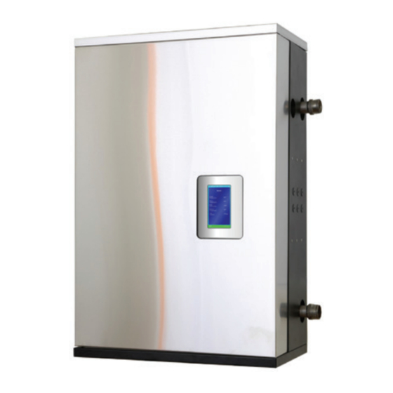
VFC 15-150 and VFC 45-225 Modulating Gas Boilers
(natural gas or propane)
INSTALLATION AND OPERATING INSTRUCTIONS
If the information in this manual is not followed exactly, a fire or explosion may
result causing property damage, personal injury, or loss of life.
Do not store or use gasoline or other flammable vapours and liquids or other
combustible materials in the vicinity of this or any other appliance.
Should overheating occur or the gas supply fails to shut off, do not turn off or
disconnect the electrical supply to the pump. Instead shut off the gas supply at a
location external to the appliance
WHAT TO DO IF YOU SMELL GAS:
• Do not try to light any appliance.
• Do not touch any electrical switch; do not use any phone in your building.
• Immediately call your gas supplier from a nearby phone. Follow the gas
supplier's instructions.
• If you cannot reach your gas supplier, call the fire department.
• Installation and service must be performed by a qualified installer, service
agency or the gas supplier.
VFCM 15225 Manual V2.1 – May 2007
Advertisement
Table of Contents
Troubleshooting

Related Manuals for IBC Technologies VFC 15-150


Summary of Contents for IBC Technologies VFC 15-150
- Page 1 IBC Technologies Inc. Vancouver, Canada VFC 15-150 and VFC 45-225 Modulating Gas Boilers (natural gas or propane) INSTALLATION AND OPERATING INSTRUCTIONS If the information in this manual is not followed exactly, a fire or explosion may result causing property damage, personal injury, or loss of life.
-
Page 2: Table Of Contents
Advanced Setup......24 DIAGRAMS ......51 2.4.4 Advanced Diagnostics....24 2.4.5 Passwords .........24 Parts Diagrams ........ 52 SEQUENCE OF OPERATION ..25 Wiring Diagram ......54 2.5.1 Standby .........25 2.5.2 Purging .........25 Sequence of Operations Flowchart 55 IBC Technologies Inc. VFC 15-150 and VFC 45-225... -
Page 3: Installation
4.0" hole marker. See section 1.4 - Venting. Combustion air 4.0" hole Figure 1 shows outer case dimensions and piping and electrical holes. Use this Figure 1. - Dimensions/Connections IBC Technologies Inc. VFC 15-150 and VFC 45-225... -
Page 4: Code Requirements
CODE REQUIREMENTS cleaning fluids, de-greasers and paint- removers all contain vapours which can The VFC 15-150 model was tested to form corrosive acid compounds when and certified under CSA 4.9-2000 / burned in a gas flame. Airborne ANSI Z21.13-2000. The larger VFC 45- chlorides such as those released with the 225 unit was approved under CSA 4.9a-... -
Page 5: Venting
Do not operate a summer exhaust fan. Close fireplace dampers. IBC Technologies Inc. VFC 15-150 and VFC 45-225... -
Page 6: Applications
PVC vs. CPVC vs. stainless from the indoor air surrounding the steel systems. In the standard boiler. configuration, VFC-series boilers can IBC Technologies Inc. VFC 15-150 and VFC 45-225... - Page 7 PVC, taking into account the highest fittings in accordance with Table 3. – e.g. possible ambient temperature in the area for a VFC 15-150 using 6 x 90º PVC elbows, of vent travel (e.g. boiler room, attic the maximum lineal measure is 90 feet and/or chase).
- Page 8 2½” or 3” pipe in the downward vertical run immediately below the 2” threaded adaptor, and elbow to horizontal before splicing in a field sourced 2½” or 3” reducing tee for mounting of the condensate trap; this IBC Technologies Inc. VFC 15-150 and VFC 45-225...
- Page 9 • Most installers prefer to run the combustion air intake pipe alongside the Figure 2. Condensate Trap Configuration vent, both to the left side of the boiler to IBC Technologies Inc. VFC 15-150 and VFC 45-225...
- Page 10 (as • DO NOT exhaust vent into a shown); lower down roof is OK. common venting system • To promote the projection of exhaust away from the building and from the IBC Technologies Inc. VFC 15-150 and VFC 45-225...
- Page 11 (e.g. north facing wall(s)). Place the 2 groups of pipes at least 3’ apart (the closest intake and exhaust pipes shall be 36” - or more – apart. Use same 24” (minimum) vertical separation as displayed above. IBC Technologies Inc. VFC 15-150 and VFC 45-225...
- Page 12 / regulator unequal venting (see Section 1.4.2 – assembly: - 3’ (0.91m) within a height Category IV Venting). Follow local of 15’ (4.6m) above the meter / code requirements. regulator IBC Technologies Inc. VFC 15-150 and VFC 45-225...
-
Page 13: Category Iv" Venting
Each opening should be covered in a grill, and have an area of 1 sq. in. per 1,000 BTUh for ALL APPLIANCES in the area. IBC Technologies Inc. VFC 15-150 and VFC 45-225... -
Page 14: Water Piping
5 inexpensive Grundfos 15-58 or Taco 008 minutes (300 seconds) after burner sized pump is normally adequate. Use a shutdown. This can be adjusted down as IBC Technologies Inc. VFC 15-150 and VFC 45-225... - Page 15 PB to ensure a controlled supply temperature, tube systems. and to prevent short cycling. Buffering should be added on the secondary piping IBC Technologies Inc. VFC 15-150 and VFC 45-225...
-
Page 16: Installation Rules
In the case of the typical and integral relays to simplify maximum limit for a radiant floor (most would enter 140°F); the floor pump IBC Technologies Inc. VFC 15-150 and VFC 45-225... - Page 17 Wiring: loop Pump/Zone Valve Terminal Block the yellow & white “Primary Pump” pair (green colour, along controller’s right up to connect to the lowest pair of IBC Technologies Inc. VFC 15-150 and VFC 45-225...
- Page 18 VFC modulating boilers or mixed pairings of either VFC boilers leading one to four units in IBC’s Fixed-Fire boiler series or other 3 party condensing units. 3-way motorized mixing valves control options are similarly covered. IBC Technologies Inc. VFC 15-150 and VFC 45-225...
-
Page 19: Gas Piping
GAS VALVE INSIDE (including 4 typical residential size pumps) is less than 4 amps. If primary / secondary piping is used, Figure 10. Typical Gas Piping with pumps to manage multiple loads, IBC Technologies Inc. VFC 15-150 and VFC 45-225... -
Page 20: Power Quality And Electrical Protection
Protection the pump's Black wire to the Yellow of this pair (switched Hot). The White/ The DC power supply (VFC 15-150) and Yellow pair should be individually the control board (both models) are each capped if the primary pump does not protected using in-line field replaceable obtain its power from this pair (e.g. -
Page 21: Thermostat / Sensor Wiring
IBC Technologies Inc. VFC 15-150 and VFC 45-225... -
Page 22: Boiler Systems And Operation
Standby- machine (standby / heat call display mode, showing real time data management etc) plus key temperature target settings. 2. burner, pumps (primary + external) and/or zone valve management IBC Technologies Inc. VFC 15-150 and VFC 45-225... -
Page 23: Access Levels
BBd = baseboards w/ reset AIR = air handler w/ reset StP = set point DHW = domestic hot water Other information is accessible using a menu based system – described in the following sections. IBC Technologies Inc. VFC 15-150 and VFC 45-225... -
Page 24: User Setup
“11111” followed by “enter” temperature settings appropriate to the A common “installer” code is also used, characteristics of the heating system. to ensure continuing access even with a change in service personnel. IBC Technologies Inc. VFC 15-150 and VFC 45-225... -
Page 25: Sequence Of Operation
On a Heating Enabled signal, the boiler trial, the interpurge cycle is entered. If automatically enters a prepurge cycle. ignition fails 3 times successively, the boiler locks out for a 1 hour long IBC Technologies Inc. VFC 15-150 and VFC 45-225... -
Page 26: Heating
DHW and other SetPoint loads (±20°F); space heating with Outdoor Reset invoked (±11°F). IBC Technologies Inc. VFC 15-150 and VFC 45-225... -
Page 27: Error Mode
Load 3) are not providing the desired based voting system will allocate heat heat, the on-time of the baseboards can amongst each of up to 3 loads over time. be increased by increasing the IBC Technologies Inc. VFC 15-150 and VFC 45-225... -
Page 28: Reset Heating
Where Outdoor Reset is applied without management algorithm flexes the boiler the indoor sensor feedback option, some supply temperature according to manual adjustment may be required to characterized heating curves that are IBC Technologies Inc. VFC 15-150 and VFC 45-225... -
Page 29: Variable Speed Pumping
Where a conventional pump is correctly 2.6.3 Variable Speed Pumping wired in accordance with the wiring One strategy to optimize combustion diagram, the pump will operate at a efficiency across the boiler's wide single, high speed. IBC Technologies Inc. VFC 15-150 and VFC 45-225... -
Page 30: Temperature Setback
4-20mA; to switch over Heating loads for which Outdoor Reset to 0-10V, remove the electrical box is activated will drop both the corner cover to provide access to the circulating water and the indoor setpoint IBC Technologies Inc. VFC 15-150 and VFC 45-225... -
Page 31: Set Up & Load Definition
Section 2.4.5. – Passwords if these are in use or desired. 4. Use the left-most key to step back to the Installer Setup screen, and select Heat Load Configuration for input of the load characteristics. IBC Technologies Inc. VFC 15-150 and VFC 45-225... - Page 32 8. For reset loads, the initial selection 9. For Reset Loads, move down the to be made addresses the “emitter” screen again to display more lines; type – choises include H(high) Mass Radiant, L(ow) Mass Radiant, IBC Technologies Inc. VFC 15-150 and VFC 45-225...
- Page 33 “Indoor Temp. …..Open”, and there as done within some boiler controls. will be no effective indoor trim of Ensure the Maximum takes account the reset curve. These lines do not of the construction and safety IBC Technologies Inc. VFC 15-150 and VFC 45-225...
- Page 34 16. Two lines below Altitude adjustment is the field for amendment of the primary pump heat purge time. To shorten the 5 minute post-firing period, reduce the 300 second interval to as low as 60 sec. Similar IBC Technologies Inc. VFC 15-150 and VFC 45-225...
-
Page 35: Startup & Commissioning
4. Turn gas control cock to CLOSE. selecting main power switch to Off. 5. Replace front cover on appliance Also ensure items under the following caption 3.1 Prior to Start-up have been addressed. IBC Technologies Inc. VFC 15-150 and VFC 45-225... -
Page 36: Prior To Start-Up
Fill condensation properly functioning combustion trap to full 7” (min) neck height for analyzing equipment. VFC 15-150 or 28” for VFC 45- Upon initial set up, the installer can 225. enter the site elevation to compensate b) Check water piping system is fully for altitude. - Page 37 “Manual Control”. Use Heat Output turn clockwise. Ensure fully closed, in “Configure Load x” to control the but not over-tightened. output as needed. Figure 12 – Gas Valve and Pressure Reference System IBC Technologies Inc. VFC 15-150 and VFC 45-225...
-
Page 38: Maintenance And Troubleshooting
1 – 3 years at clean burners will only need attention every commercial applications. 2 – 5 years. Consider adding air filtration if IBC Technologies Inc. VFC 15-150 and VFC 45-225... - Page 39 - e.g. 10°F load and/or the respective Minimum between supply and return when firing at Temperature setting. 75,000 Btu/hr. for a VFC 15-150 unit. If a problem exists with the control, consult Gas Piping troubleshooting guide.
-
Page 40: Component Description
Compound between the base of the hi- the range — 15 - 150 MBH for VFC 15- limit switch and the mounting surface. 150 or 45 – 225 MBH for VFC 45-225. IBC Technologies Inc. VFC 15-150 and VFC 45-225... - Page 41 Function: Senses water temperature. Signals controller to adjust output On-board field replaceable fuses are 5A, according to water temperature. slow blow, 5mm x 20mm, and must be replaced using these same specs. IBC Technologies Inc. VFC 15-150 and VFC 45-225...
-
Page 42: Troubleshooting Guide
5,000 kΩ (5,000,000Ω) at the controller end of the sensor lead). To obtain a resistance reading, remove power to the boiler. Locate the blue 2-wire leads coming from the tekmar 071 sensors, which are affixed to the boiler supply and return piping IBC Technologies Inc. VFC 15-150 and VFC 45-225... - Page 43 ; to check, the simplest technique is to measure the circuit on the face of the controller circuit board (vs. an attempt to splice into the harness / connectors). See below for a presentation of the measurement points. IBC Technologies Inc. VFC 15-150 and VFC 45-225...
- Page 44 AC voltage across the device. If the reading is 24 VAC the switch is open. If a 0VAC reading is shown, it is closed. NEVER connect an ohm-meter or continuity checker across a live circuit. IBC Technologies Inc. VFC 15-150 and VFC 45-225...
-
Page 45: Troubleshooting Using The Control45
(indicates no flow). • Check temperature differential across heat Check for restriction in water pipe. exchanger at low –medium firing rate if possible. Examine air strainer components for scale IBC Technologies Inc. VFC 15-150 and VFC 45-225... - Page 46 • Push manual reset button, maintain constant watch during boiler operation to evaluate vent temperature at maximum operating settings to ensure no unsafe condition exists, e.g. max flue temp. within allowable limits for exhaust pipe material used. IBC Technologies Inc. VFC 15-150 and VFC 45-225...
-
Page 47: Detailed System Checks
Unit over-fired. Clock gas meter/check gas pressure with manometer/ check level. Unit Oversized. Check load calculation vs. min. boiler output Improperly set or defective Check operation with operating/safety controls ohmmeter/voltmeter IBC Technologies Inc. VFC 15-150 and VFC 45-225... - Page 48 • Check temperature sensor – see Section 4.3.2.1. Miscellaneous Indicative of power-surge damage to appliance LCD Screen Message Blank – screen dark, but fan running • Check transformer; replace if damaged • Check circuit board for visible damage IBC Technologies Inc. VFC 15-150 and VFC 45-225...
- Page 49 Diagnosis Remedy Fumes and High Humidity Improperly installed Refer to installation/operation condensate trap instructions Leak in vent piping Inspect using soap solution Flue gas leak within Visually inspect all boiler mechanical connections IBC Technologies Inc. VFC 15-150 and VFC 45-225...
- Page 50 Intentionally Blank IBC Technologies Inc. VFC 15-150 and VFC 45-225...
-
Page 51: Diagrams
5 DIAGRAMS See Following Pages 5.1 – Parts Diagrams 5.2 – Wiring Diagrams 5.3 – Sequence of Operations Flowchart IBC Technologies Inc. VFC 15-150 and VFC 45-225... -
Page 52: Parts Diagrams
Parts Diagrams VFC Modulating Boilers – VFC 15-150 and VFC 45-225 (Parts are common to both models unless marked: (a) for VFC 15-150 and (b) for VFC 45- 225) Description Pt # Fan Coupler 01-FCA-L FCA Gasket 02-Gsk-FCA 10-32 hex cap screw x4... - Page 53 Water pressure sensor (2) 63-H505 P sensor brass mount (2) 64-HBrass No longer used with H505 Nylon cable tie (2) 66-tempclamp (***) specify PVC or CPVC, and if applicable, IPEX System 636™ IBC Technologies Inc. VFC 15-150 and VFC 45-225...
-
Page 54: Wiring Diagram
Wiring Diagram Wiring Diagram for VFC 15-150 and VFC 45-225 Modulating Boilers IBC Technologies Inc. VFC 15-150 and VFC 45-225... -
Page 55: Sequence Of Operations Flowchart
Sequence of Operations Flowchart IBC Technologies Inc. VFC 15-150 and VFC 45-225... - Page 56 Intentionally Blank IBC Technologies Inc. VFC 15-150 and VFC 45-225...
- Page 57 VFC-Series Hot Water Boiler Your IBC Virtual Fuel Cell boiler is backed by this limited 12 year warranty IBC Technologies Inc. warrants each boiler to be free from defects in material and workmanship in accord with the following terms, conditions and periods:...
Need help?
Do you have a question about the VFC 15-150 and is the answer not in the manual?
Questions and answers