
Subscribe to Our Youtube Channel
Related Manuals for ATG A3

Summary of Contents for ATG A3
- Page 1 User Manual for Flying Probe Test System V3.7 Click on a line in the table of contents to jump to the corresponding chapter.
- Page 2 Before turning on the system, the operator must have read this quick reference manual especially observing the documented safety precautions. As far as no appropriate training on part of the company atg has taken place the operator is not authorized to carry out the following activities:...
-
Page 3: Table Of Contents
Software Certificate ..............A-9 Information for users .................... A-9 1. System Overview ..................A-10 1.1 Unloading and Transporting the Flying Probe Test System A3 ....A-10 1.2 General View of the Test System ..............A-12 1.3 General View of the Shuttle ................ A-14 1.4 Assembly Rack ................... - Page 4 Test system A 3 V3.7 5.2.5 The Beginning of the Test ................ B-20 5.2.6 Pausing and Resuming a Test ..............B-20 5.2.7 Canceling the test ..................B-20 5.3 Test Result Output ..................B-21 6. Removing the tested Board and inserting a new One ........B-24 6.1 Turning off the Test System .................
- Page 5 Test System A 3 V3.7 8.4.3 Removal of the entire Needle Fixture ............D-9 8.5 Z-Axis Removal ...................D-11 8.6 Z-Axis Installation ..................D-13 8.6.1 Preparation ....................D-13 8.6.2 Assembly ....................D-14 8.6.3 Final Test ....................D-15 8.6.4 Error Messages after Z-axis Installation and their Probable Causes ..D-16 8.7 Avoiding Test Head Damages ..............D-18 8.8 Testing Flexible PCBs .................D-19 8.8.1 The Simple frame ..................D-19...
-
Page 6: Directions For Avoiding Personal Injuries
Test system A 3 V3.7 Directions for avoiding personal injuries In order to avoid personal injuries, the following directions should be paid attention to: General Directions Observe all safety and danger directions on the test system. Only electrical specialists or trained personnel supervised and guided by an electrical specialist according to the electrical engineering regulations are authorized to carry out work on the electrical equipment of the test system. - Page 7 Test System A 3 V3.7 In case of working on high voltage assembly racks connect the power cable to the ground after switching the power off. Then short-circuit the assembly components such as the capacitors with a grounding bus. Safety Directions for Product Defects In order to avoid product defects the following should be observed: Do not carry out any program changes (software) to programmable control systems! Organizational Directions...
- Page 8 Test system A 3 V3.7 Maintenance Directions Make sure to meet the deadlines for adjustment, maintenance and inspection activities and appointments set in the operator’s manual including the information for exchanging parts/partial equipment! Trained and qualified personnel may only do these activities. Before carrying out extraordinary or reparation activities always make sure to inform the operator! Appoint a responsible supervisor! Carry out all activities concerning operation, production adaptations, changes or...
-
Page 9: Atg Test Systems Software Certificate
You further do not have the right to provide third parties with this software unless you sell or lease it together with the rest of the atg test system or to modify the software programs in any way. -
Page 10: System Overview
The user is responsible for the company internal transport of the test system even in the presence of atg personnel. Furthermore, he must pay attention that all safety and accident prevention precautions are observed. The appropriate safety gear is to be worn during these activities. The applied transport devices (crane and lifting devices, forklift, hand forklift etc.) must be... - Page 11 Size Test System A3 Space requirements Test System A3 Width 2.60 m Width 4.10 m Depth 1.15 m Depth 3.00 m excluding operator’s working Height 1.90 m (opened) area Set-up, installation and putting into operation only by atg test systems service personnel! A-11...
-
Page 12: General View Of The Test System
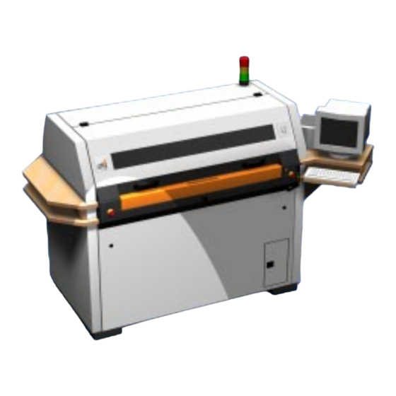
Test system A 3 V3.7 1.2 General View of the Test System Fig. 1: General view of the A3 test system A-12... - Page 13 Test System A 3 V3.7 Position Description/Function Main Power Switch (gray rotary switch) Machine On/Off Emergency Off Machine Stop Release of shuttle clamp (yellow button) Release fine adjust for turning knob no. 10 Illumination controller top camera Illumination controller bottom camera (option) Control on (green button) Machine control on Control off (red button)
-
Page 14: General View Of The Shuttle
Test system A 3 V3.7 1.3 General View of the Shuttle Fig. 2: General view of the A 3 shuttle A-14... - Page 15 Test System A 3 V3.7 Position Description/Function Handle for shuttle Fixing screws for left holder Limit stop of shuttle Fixing screws right Holder Tension lever for lateral pressure Spring loaded tense for head on pressure Fixing screws for front holder Clamp pieces Fixing screws for rear holder C-Adjust-Board...
-
Page 16: Assembly Rack
Test system A 3 V3.7 1.4 Assembly Rack Fig. 3: Assembly racks A-16... - Page 17 Test System A 3 V3.7 Position Description/Function Netcard for measure power supply ±15 V / 5 V Extender-I/O-card Head Controller / Motor Driver, Camera(s) Measurement Controller A_MUX (analog-multiplexer) High voltage measuring card (HV 500), option I/O-Controller (control card) Crate Controller (main control card) Head Unit / Motor Driver, Rail 0 (top, front) Head Unit / Motor Driver, Rail 1 (top, rear) Head Unit / Motor Driver, Rail 2 (bottom, front)
-
Page 18: Test Requirement For Repaired Boards
Test system A 3 V3.7 1.5 Test Requirement for Repaired Boards Boards tested faulty are often repaired and reused. Repaired boards must be retested in a complete test. Only a complete new test can give a correct good-result because there can be certain fault constellations which can prevent the finding of all other faults (see figure). -
Page 19: The Operating Modes Of The A3 Test System
Test System A 3 V3.7 1.6 The Operating Modes of the A3 Test System The Test Player, the control software of the test system, offers two different operating modes: 1. The User Mode is active directly after starting the Test Player. The user mode provides all basic test functions, most parameters, however, cannot be modified in the user-mode. -
Page 20: Turning On The Test System
Test system A 3 V3.7 2. Turning on the Test System 1. Turn the Main Power Switch (Fig.1, No.1) to the On-position The Control Off lamp (red key) is illuminated The control PC boots The fan of the control unit starts to run 2. - Page 21 Test System A 3 V3.7 The test system now loads different files and scans the hardware settings in a self- diagnosis. The signal light shines red. The test system is initialized. The test probes carry out a short movement. After having started the TestPlayer-software the input window Authorization appears.
-
Page 22: The User Mode
User Mode A 3 V3.7 3. The User Mode 3.1 The User Interface of the User Mode Hint: Screen displays in this handbook may not be equivalent to the displays on your monitor due to different software versions in use. However, this has no influence on the descriptions of the functions. -
Page 23: Status Field
User Mode A 3 V3.7 3.1.1 Status Field The left section of the TestPlayer-window shows the current test status. The individual information lines in detail: Status: Display of the currently executed function. Done: Time bar indicating the test progress. PCB: Name of the tested board. -
Page 24: Buttons
User Mode A 3 V3.7 3.1.2 Buttons The buttons are located in the window’s right section. A button can be activated either by clicking it with the mouse or by pressing the appropriate function key (e.g. F3 for Load Board) indicated on the button. Depending on the current test status of the TestPlayer, only certain commands are available. -
Page 25: Load Job
User Mode A 3 V3.7 3.2 Load job In order to a test a new PCB you need to load its job (work data). Therefore, either click the Load PCB-button or simply press the F3-key. Hint: In order to execute a proper test run various prerequisites must be met described in the Chapter Supervisor Mode (e.g. - Page 26 User Mode A 3 V3.7 Selection-window Select PCB From the given list load the desired job. In order to select a job you can either use the scrollbar on the right side of the window and click on the desired one or you can jump to the job’s first letter by using the keyboard (e.g.
-
Page 27: Adjusting To A New Board
User Mode A 3 V3.7 4. Adjusting to a New Board 4.1 Ejecting the Shuttle Now set the board into the shuttle. Therefore, open the shuttle locking-mechanism by clicking on the Shuttle-button (F6). You will hear a clicking. Manually pull out the Shuttle out of the machine until the locking-mechanism automatically engages in the outer position. -
Page 28: Adjusting The Product Holders
User Mode A 3 V3.7 Annotation: The shuttle can be unlocked in two different ways: 1. If the TestPlayer’s main-window is open, unlock the Shuttle by clicking the Shuttle- button (F6). 2. If the Shuttle-window is open, unlock the Shuttle by clicking OK. The Shuttle will not be unlocked if the Cancel-buttons clicked. - Page 29 User Mode A 3 V3.7 Display of the board position in the shuttle with the button Show Board (F8) Re-clicking the Show Text (F8)-button returns you to the working window. In the window Shuttle (F6) the loaded board file displays the required positions of the product holders.
- Page 30 User Mode A 3 V3.7 Lay the board on the surfaces of the terminal bars of the left and rear holder and push the right holder against the board until it is safely fixed. Pay attention towards proper board positioning! Re-tighten both clamp screws of the right holder.
-
Page 31: Starting A Test In User Mode
User Mode A 3 V3.7 5. Starting a Test in User Mode You can begin testing after the board adjustment is complete and the shuttle is in the system. With the mouse, click the Start Test-button (F2). The input window Start test appears. Input window Start test Enter the serial number of the board into the Board serial number-field. - Page 32 User Mode A 3 V3.7 Annotation: For testing a new lot its automatically pre-assigned lot number should not be changed. If you wish to assign a lot a specific number enter the desired number into the lot number-field. The button Retest the same board is only activated if a board had already been tested.
-
Page 33: Button Test Params (F5) In The User Mode
User Mode A 3 V3.7 5.1 Button Test Params (F5) in the User Mode In the User mode there are under button Test Params (F5) two tab-boxes available: Skip Panel and Misc. 5.1.1 Tab-box: Skip panels Panel selection window For multi-panel testing, you can exclude individual panels from testing with the Test Params (F5)-button. -
Page 34: Tab-Box: Misc
5.1.2 Tab-Box: Misc Tab box: Misc Field Not functional with test system A3. Debug / Wait mode Perform testing step by step. Motions and measurements of the task file are se- quentially executed. Consequently, the test speed is reduced facilitating the ana- lysis of the detected faults. - Page 35 User Mode A 3 V3.7 Debug / Pause after error Interrupt testing (identical to Pause Test (F4)). Pause after error, only discontinu- es testing if a fault (open or short) is detected. The button Pause Test (F4) switches to Resume Test (F4). The message ”Test Paused”...
-
Page 36: Scanning (Determining The Board Position With The Camera
User Mode A 3 V3.7 5.2 Scanning (Determining the board position with the camera) The first step in the test procedure is the scanning. Due to the mechanical toleran- ces, the individual boards always show a slight difference between their actual position in the shuttle and their required position defined by the test data. - Page 37 User Mode A 3 V3.7 Example for correct placement of scanmarks: red scanmark and black camera marks have their position exactly on the pads Attention: Position the red scanmark exactly on the corresponding pad of the camera picture! Hint: possible causes of board and camera scanmark incongruence: - board improperly fixed - wrong board fixed - net list contains no or false board contours...
-
Page 38: Manual Scanning
User Mode A 3 V3.7 5.2.1 Manual scanning Every scanmark must be placed manually if manual scanning was set in the supervisor mode. Attention: The decisive red scanmark of the camera must be exactly positioned on the concerned pad of the board. -
Page 39: Automatic Scanning
User Mode A 3 V3.7 The skipped panels are crossed-out. Panels marked with a violet cross show a bigger shift than allowed. The purple crossed-out panels show a too large offset. The shift of an individual panel is shown in the right if the mouse positioned on it. Inspect the possible reasons for a big shift. -
Page 40: Wrong Board Position
User Mode A 3 V3.7 5.2.3 Wrong Board Position The scanning procedure is canceled if the test system detects a too big offset between the actual scanmark position and the one given in the test data. The following warning is displayed: In this case, check the following: - Product holders properly adjusted? - Board properly inserted? -
Page 41: The Beginning Of The Test
User Mode A 3 V3.7 5.2.5 The Beginning of the Test The test system automatically starts the test run after the scanning. The line TEST RUNNING flashes and the board faults and the test time are displayed. Test running 5.2.6 Pausing and Resuming a Test Click the Pause-button (F4) to pause testing. -
Page 42: Test Result Output
User Mode A 3 V3.7 5.3 Test Result Output After a test run is completed, the test results are put out in the Test information box. Test results In the shown board view, faultless panels are displayed green and faulty panels red. - Page 43 User Mode A 3 V3.7 The setting Ask before printing of the supervisor mode allows the user to select the kind of output. Therefore, the window Select report output is displayed. Here, the test results can also be put out in several variants after each other. Output selection via ”Ask before printing”...
- Page 44 User Mode A 3 V3.7 With the button Select fault of the Retest window, you can select and retest both pads of a single fault from the loaded faults list. The Faults list window is opened for selecting a fault retesting with a double-click. In the bottom section of the window, select the type of faults to be retested (Opens, Shorts etc.).
-
Page 45: Removing The Tested Board And Inserting A New One
User Mode A 3 V3.7 6. Removing the tested Board and inserting a new One After a board was tested and its results were put out a new one can be inserted. For this purpose the shuttle can remain in its inserted position. Open the shuttle locking and pull out the shuttle. -
Page 46: The Supervisor Mode
Supervisor Mode A 3 V3.7 7. The Supervisor Mode 7.1 Introduction After starting the Test Player-program you are in the user mode. The user mode provides you with all necessary basic functions for the circuit board test. The Test Player in the user mode From the user mode, you can activate the Supervisor-mode through a password. -
Page 47: Switching To The Supervisor Mode
Supervisor Mode A 3 V3.7 7.2 Switching to the Supervisor Mode In the task window of the window Test Player once click on the control-menu-box in the upper left in order to open the menu for switching to the supervisor mode. Menu Item Password The pull down menu for changing the operator mode appears. - Page 48 Supervisor Mode A 3 V3.7 Opening screen supervisor mode For returning to the User Mode just enter the password again in the same manner as described before.
-
Page 49: Changing The Password
Supervisor Mode A 3 V3.7 7.3 Changing the Password After the first installation of the A 3-software package no password is set. The supervisor functions are therefore freely accessible to anyone. The test system can be password protected and the password can be changed at any time. In order to enter a password, switch to the supervisor mode and open the control menu box in the upper left of the Test Player-window. -
Page 50: Generate Service Data
7.4 Generate Service Data The item Generate service data creates a directory with different files, which will enable a service department employee of "atg test systems" to recognize the cause of a test problem. This service-file will be written to directory C:\programms\atg\dump as a compressed ZIP-file. -
Page 51: Test Statistics
Supervisor Mode A 3 V3.7 7.5 Test statistics You can always open the wirndow Testplayer statistic. This window shows a summary of the done jobs sice turning on the test system. Total amount of test runs Runs of current job Good runs of current job Faulty runs of current job Average test time... -
Page 52: The Operating Window Of The Supervisor Mode
Supervisor Mode A 3 V3.7 7.6 The operating window of the supervisor mode The software buttons of the user mode are also functional in the supervisor mode. Modified or new are: – for a job loaded, the function Show <boardname> is available in the top menu bar of the action window, providing an extensive sub-menu. -
Page 53: The Functions Of The New Supervisor Mode Buttons
Supervisor Mode A 3 V3.7 7.7 The Functions of the new Supervisor Mode Buttons In the supervisor mode, the following new buttons are available in the right side of the window: Button Find Pad (F8) With the button Find pad, you can find individual pads on the board with the camera or contact them with a test probe. -
Page 54: The Main Menus Of The Supervisor Mode
Supervisor Mode A 3 V3.7 7.8 The Main Menus of the Supervisor Mode 7.8.1 The Main Menu Faults In the Faults main menu, you can retest the entire or selected parts of the faults data of a loaded and fastened board and carry out ohmic measurements between two pads of your choice. -
Page 55: The Menu Items Of The Main Menu Faults
Hint: An extensive verification mode is offered by atg test systems for all flying probe test systems. With this verification extension you can retest found faults (also from grid test systems). - Page 56 Supervisor Mode A 3 V3.7 Lot- and Run Selection Following the run number, the faults it includes are shown in abbreviations. For the case that the selected run contains no fault data the program will display: No Faults in selected lot or run 7.8.2.2 Retest all The menu item Retest all can only be activated after you have loaded a fault file with at least one fault with the menu item Load Faults.
- Page 57 Supervisor Mode A 3 V3.7 Retest all Hint: In the menu item Retest all you cannot refresh your fault file. Furthermore, it is impossible to printout the contents of this window. You can apply the menu item Retest all for the inspection of repaired boards.
- Page 58 Supervisor Mode A 3 V3.7 Retest Selected The menu item Retest Selected additionally contains the button Select faults, which opens the selection window Faults list in which you can make a selection of the faults to be retested. Fault Selection List The bottom of the Faults list-window all possible fault types of the loaded run are listed.
- Page 59 Supervisor Mode A 3 V3.7 In the top of the selection window the individual faults of the activated fault type are displayed. Faults marked for retest are checked off. For (de) activating a fault, remove or add its marker with a mouse click or by pressing the space bar. With the buttons Select all <Fault type>...
- Page 60 Supervisor Mode A 3 V3.7 Select Pads for Retest With the Select fault-button you can select the pads of an individual fault from the loaded faults list. The Faults list-window is opened from which a fault can be selected. Select Faults for Retest C-15...
- Page 61 Supervisor Mode A 3 V3.7 The functions of the Fault list window are described in the menu item Retest Selected (p. C-10). Start the individual test with a double-click on the desired fault of the faults list. During this the faulty pads are transferred to the Retest-window and the test results are displayed.
-
Page 62: Main Menu Debug
Supervisor Mode A 3 V3.7 7.8.3 Main Menu Debug Main Menu Debug 7.8.3.1 Hard Reset The menu item Hard Reset sets back all controller cards. During this, the power supply of the test system is not interrupted; however, all internal program activities are deactivated. - Page 63 Supervisor Mode A 3 V3.7 This command does not have a negative effect on the test system; it only produces a defined condition. Only execute a Soft Reset when the test system is inactive. 7.8.3.3 Load With the sub-menus of the menu item Load you can reload necessary system programs and data required for the initialization of the test system, either individually or entirely (e.g.
- Page 64 Supervisor Mode A 3 V3.7 7.8.3.4 Find Pad With the menu item Find Pad you can find individual pads on the board with the camera or contact them with a test probe. The board must have been scanned before; otherwise this menu item cannot be started. Is the opposite the case, the board is first scanned automatically after the function Find Pad was executed.
- Page 65 Supervisor Mode A 3 V3.7 7.8.3.5 Wait Mode With the menu item Wait Mode you can run the test procedure step by step. Movements and measurements of the task file are executed sequentially. During this, the test speed is reduced and the analysis of the detected faults is therefore facilitated. Due to the reduced test speed it is now possible to online display information about the test procedure in the status window.
- Page 66 Supervisor Mode A 3 V3.7 7.8.3.9 Strokes The menu item Strokes tells you how often test probes have made contact during their operating life. This way you can keep track of their operating life. The statistics file strokes.cnt of the \hardware-directory is listed for this purpose. This file is actualized with each Soft-Reset.
- Page 67 Supervisor Mode A 3 V3.7 The remaining coefficients represent internal calculations results and are of no interest to the user. Hint: It is impossible to activate the menu item Scan Board, if scanning was disabled in the Test Params (F5). The Advanced-button opens the Advanced Video Setup-window.
-
Page 68: Main Menu Options
Do not use the menu item Call flying debugger for executing a C-Adjust or for calibrating the test system. Use the separate program icon Debug32 on the Win- dows NT desktop. This menu item is only used for the atg service support. Start Debugger... -
Page 69: Main Menu Item Show
Supervisor Mode A 3 V3.7 7.8.5 Main Menu Item Show <boardname> Starting the sub-program Show <boardname> After having loaded a job, the main menu item Show <boardname> is available, via which you enter an extensive, graphically oriented sub-program. In this sub-program you can read back all relevant information on the tested board. - Page 70 Supervisor Mode A 3 V3.7 Sub-program Show <boardname> The main menu item Show <boardname> displays the board in a green line graphics representing the operating areas of the individual rails. Additionally, three vertical striped lines are shown. The outer lines represent the margins of the camera operating range in X-direction while the middle line shows the test field center and serves as orientation.
- Page 71 Supervisor Mode A 3 V3.7 - Pad info - Find pad - Net info - Find Net - Add Scanmark (only available if not all scanmarks are placed ) - Delete Scanmark (only available if a scanmark is placed on the test pad) Pop up menu: Commands for pads and nets The following functions are available if the cursor is not located on a test pad (recognizable in the info bar) when the right mouse-button is pressed:...
- Page 72 Supervisor Mode A 3 V3.7 Pop up menu for graphic commands 7.8.5.1 The Functions of the pop up menu on a Test Pad Pad Info With this function you can call up information on a test pad. When this function is active the cursor has the shape of an arrow with a question mark.
- Page 73 Supervisor Mode A 3 V3.7 Example for Pad-IDs on multi-panels: A net list consists of 10 nets (net number 1-10) and 50 pads. With one Step&Repeat- line you have created a double-panel. Consequently, in the first panel you will only receive pad-IDs between 1 and 50 and net numbers between 1 and 10.
- Page 74 Supervisor Mode A 3 V3.7 Find Net Input window Find Net For finding a certain net on the board. In the displayed input window enter the wanted net number. In the graphic, auxiliary lines connect all pads of the net and the net information appears in the info bar.
- Page 75 Supervisor Mode A 3 V3.7 Delete Scanmarks With the menu item Delete Scanmarks you can erase set marks. Position the cursor on the scanmark to be erased, click the left mouse-button and select Delete Scanmark. The scanmark symbol on the test pad is deleted. 7.8.5.2 The Functions of the Pop up menu outside of Test Pads Zoom Reset...
- Page 76 Supervisor Mode A 3 V3.7 The measured pads show a distance of 1.14 mm in X-direction and 4.65 mm in Y- direction between each other. The next mouse click deletes the measuring result in the info bar. Fast Move Fast Move (or the M-key) enables you to move the zoomed section without changing the zoom-factor (helpful for placing/deleting scanmarks).
- Page 77 Supervisor Mode A 3 V3.7 This function is especially helpful if several boards are fastened in the shuttle and scanmarks are to be placed individually on each board, or for the separate scanning of high pitch areas, or also for trapezoid distortions on multi-samples. Set dividing line Here, you must select whether the scanmark area is to be divided vertically or horizontally.
-
Page 78: The Main Menu Tools
Supervisor Mode A 3 V3.7 7.8.6 The Main Menu Tools Main menu tools of the sub-program Show <boardname> The following functions are available in the main menu Tools - Distance (also included in the pop up menu of the right mouse button) - Fast Move (also included in the pop up menu of the right mouse button) - Pad Info (also included in the pop up menu of the right mouse button) - Find Pad (also included in the pop up menu of the right mouse button) - Page 79 Supervisor Mode A 3 V3.7 Additional functions of the main menu DPS are: 7.8.6.1 Deselect Pad The menu item Deselect Pad is only active if a test pad was selected with Find Pad. With it you can remove the reticule from the selected pad. 7.8.6.2 Deselect Net The menu item Deselect Net is only active if a test pad was selected with Net Info.
- Page 80 Supervisor Mode A 3 V3.7 Pad Size Filter function for selecting pad types of a certain size (Unit: 1/100mm). This function uses the value of the input line Filter Params (Pad size below) as reference value, displayed in the bottom of this window. The following filters are available: - Pad size below Show all pads that are smaller than the entered value.
- Page 81 Supervisor Mode A 3 V3.7 Pad Color Assignments In the function Element Type select the pad type to which you would like to assign a different color and then select the board side for the color assignment (component- or solder side). For adjusting the color, three sliding controllers are available.
-
Page 82: Main Menu View
Supervisor Mode A 3 V3.7 7.8.7 Main Menu View In the main menu View you can either show or hide the display of the outer layers. The menu item Both sides shows both layers. The menu item Top only shows only the component side and the menu item Bottom only exclusively the solder side. - Page 83 Supervisor Mode A 3 V3.7 Main Menu Scanmarks - Null No scanning - Whole board You can place 2,3 or 4 scanmarks on a single panel or a multi sample. The number of scanmarks is calculated per section. (Division in sections see Chapter “Pop up Menu outside of pads”) - Each panel/sample For multi samples you can place 2,3 or 4 scanmarks on every single panel.
- Page 84 Supervisor Mode A 3 V3.7 Select scanmark side The set scanmark appears as colored symbol on the test pad. Hint: In the graphic sub-program you at all times have access to the Add Scanmark- command via the right mouse-button if the cursor is positioned on a test pad. However, this is only possible if not all 4 scanmarks (per section) are placed.
- Page 85 Supervisor Mode A 3 V3.7 7.8.8.4 Comp. Side Color With the menu item Comp. Side Color you can define the color in which the scanmarks of the component side are to be displayed. Color Selection for component side pads For adjusting the color three slide controllers are available. Every color has 255 brightness levels, which can be combined with each other as desired.
-
Page 86: Main Menu Antennae
Supervisor Mode A 3 V3.7 7.8.9 Main Menu Antennae In the main menu Antennae you can both display antennae and adjust their color. Main Menu Antennae 7.8.9.1 Show antennae With the menu item Show antennae you can display the DPS generated antennae nets. - Page 87 Supervisor Mode A 3 V3.7 Example: 2/1 = 2. Antennae net for panel 1 The option None hides the antennae. 7.8.9.2 Antennae Color With the menu item Antennae Color you can define the color in which the antennae are to be displayed in. Color Selection for the Antennae Display For adjusting the color three slide controllers are available.
-
Page 88: Main Menu Faults
Supervisor Mode A 3 V3.7 7.8.10 Main Menu Faults In the main menu Faults you can graphically display faults. Main Menu Faults of the sub-program Show <boardname> 7.8.10.1 Load Faults With the menu item Load Faults you can load faults for graphically displaying them. In the appearing selection window Select faults Lot &... - Page 89 Supervisor Mode A 3 V3.7 The first fault of the test run is immediately shown in the screen and the corresponding fault information is displayed in the info line in the left. A yellow line for an existing open or a short connects both fault pads. The pads are highlighted in green for faults like No contact or Bad Field.
- Page 90 Supervisor Mode A 3 V3.7 Selects Faults for Display Hint: atg test systems offers the option "verification mode". This expansion of the TestPlayer has extensive possibilities to verify faults from flying probe and grid test systems. C-45...
-
Page 91: Main Menu Markers
Supervisor Mode A 3 V3.7 7.8.11 Main menu Markers With the menu Markers you can define the number of printer marks. Not available for manual test system. 7.8.11 The Main Menu Item Close With a mouse click on the menu item Close you switch back to the supervisor mode work window. -
Page 92: Action Buttons Of The Supervisor Mode
Supervisor Mode A 3 V3.7 7.9 Action Buttons of the Supervisor Mode The supervisor mode provides 8 buttons associated with the function keys F2 through F9. The buttons F2 through F7 have the same functions as in the user mode. Additionally, the buttons Step by Step (F8) and Exit (F9) are available. The functions of the Test Params (F5) button are greatly expanded in the super- visor mode. - Page 93 Supervisor Mode A 3 V3.7 Exit (F9) The Exit (F9) button closes the TestPlayer. Hint: The option button verification is only availably if the erscheint nur, wenn der dafür benötigte Dongle aufgesteckt ist. C-48...
-
Page 94: Button Test Params (F5
Supervisor Mode A 3 V3.7 7.9.1 Button Test Params (F5) The settings of the Test Params-button define the conditions for the test procedure. Opening window Test Params The Current test state, a summary of all important parameters in their current status, is displayed in the bottom right for all menu items of the Measurement Parameters- window. - Page 95 Combined Enables the combined test method, prepared in DPS. Opti- on for test system A3. Opens and shortstest in 1 test run. Approx. 10% faster test. Hint: Disabling the opens test simultaneously disables the shorts test. The opens test must be enabled for being able to select further test types.
- Page 96 Supervisor Mode A 3 V3.7 7.9.1.2 The Parameter-Menu Shorts Test Parameter-Menu Shorts Test The tab box Shorts Test defines the settings for the shorts test. Test type – Disabled Shorts test disabled – F/M Field Measurement Shorts are determined via field-measurement. The retest is a resistance test. - Adjacency Only functional with an existing adjacency-file.
- Page 97 Supervisor Mode A 3 V3.7 Possible shorts found with the field measurement are not retested if they are not included in the adjacency-file. Shorts clearly detected with the field measurement (Short to antennae) are put out even if they are not included in the adjacency-file. –...
- Page 98 Supervisor Mode A 3 V3.7 – Threshold Here, you can define up to which resistor value (in Ohms) a short is detected. Standard value 10 MOhm. (Adjustable range 0.5 MOhm - 10 MOhm) Retest – F/M This option cannot be disabled. If the test system receives insufficient measuring results from the field measurement, nets with contradictory measuring results are automatically retested (Field-Retest).
- Page 99 Supervisor Mode A 3 V3.7 7.9.1.3 The Parameter-Menu HV-Test Parameter-menu HV-Test The tab box HV-Test (High-Voltage-test) defines the settings for the high voltage test. These options are only available if the DPS generated an HV-test. – High-Voltage HV test en/disabled –...
- Page 100 Supervisor Mode A 3 V3.7 7.9.1.4 Parameter-Menu LA-Test Parameter-Menu LA-Test – Test Type LA-default test only with additional hardware. – Stop after...opens Testing is automatically canceled if the here entered value of LA-opens per panel is obtained. – Threshold Here, you define below which LA-value a connection is intact.
- Page 101 Supervisor Mode A 3 V3.7 7.9.1.5 The Parameter-Menu Comp Test Parameter-Menu Comp Test The menu item Comp Test (component test) provides optional board testing methods. They can be obtained as add-ons to the software package and are not included in the standard version. Components test –...
- Page 102 Press force of the probe on the contacted pad. Standard value 40 g. (Adjustable ranges 10 g - 100 g in 5 g-steps). Due to specifications pressure range on test system A3 is 30-300 g. – Z-up Maximum hight of the needles above the board.
- Page 103 Supervisor Mode A 3 V3.7 The test system reduces the Z-axis stroke to the Min-up-value for increasing the test speed, only if the board topography allows this. This option can be disabled with the setting PCB- Holder / Used of the parameter window Misc. –...
- Page 104 Supervisor Mode A 3 V3.7 7.9.1.7 The Parameter-Menu Scanning Parameter-Menu Scanning In the Scanning-menu you define the conditions for the scanning process. - Disabled Disables the optical scanning. This option is always enabled if no scanmarks are placed. Attention! The board offset and shift are not considered if testing is started without prior scanning! Consequently, the test probes only move according to the internal correction file (correction tables of the...
- Page 105 Supervisor Mode A 3 V3.7 – One move Reduces the accuracy of camera evaluation and reduces the duration of scanning. Suitable for large, simple pads. – Acc mode Increases the accurady of camera evaluation and prolongs the duration of scanning. Improves the recognition in fine pitch areas and areas with much details.
- Page 106 Supervisor Mode A 3 V3.7 7.9.1.8 The Parameter-Menu Skip Panels Parameter-Menu Skip Panels In the Skip Panels-menu you define, for multi-sample testing, which panel is excluded from testing. This menu is also available in the user mode. Additionally, this function is provided in the Start test-window via the Show panels-button when starting a test.
- Page 107 Supervisor Mode A 3 V3.7 7.9.1.9 The Parameter-Menu Misc Parameter-menu Misc Field Not functional with docked loading/unloading unit! Execute a capacity check of the used test probes. For Calibration enabled, the camera is additionally directed to the brass pads of the left product holder after scanning the board.
- Page 108 Supervisor Mode A 3 V3.7 Resistance 2 <-> 3 [5 <-> 385 / 3] Explanation: A resistance measurement was executed with the probes 2 and 3 between the point Ids 5 and 385 of panel 3. Wait mode is enabled if it is checked off in the pull down menu. Hint: Wait mode can be turned off during the test leading to its continuation at regular speed.
- Page 109 Supervisor Mode A 3 V3.7 7.9.1.10 The Parameter-Menu Printout Parameter-Menu Printout In the Printout-menu you define the settings for the printout of the test results. - Ask before printing After a test the window Test information box is displayed. After pushing the Print report-button the selection window Select report output appears.
- Page 110 Supervisor Mode A 3 V3.7 Continuous printout Only functional for fully automatic version of test system (A3-a). Multi-sample printout In the selection window Samples every single panel or panel group is printed out with its own header information, depending on the number of entered panels Samples Enter the number of desired headers.
- Page 111 Supervisor Mode A 3 V3.7 7.9.1.11 The Parameter-Menu Marking In the Printout menu you set the number of samples which are marked in automatic test. Not available for manual test system. C-66...
-
Page 112: Appendix
Appendix A 3 V3.7 8. Appendix 8.1 Starting the Debugger The parameters for maintenance and calibration activities are located in the Debugger. In order to start the Debugger you must first exit the TestPlayer. Start the Debugger by clicking on the Debug32-icon on the Windows NT desktop. Working with the functions of the Debugger may lead to great maladjustments of the test system and possibly damage it! Only change parameters you are familiar... -
Page 113: How To Calibrate The A 3 Test System
Appendix A 3 V3.7 8.2 How to Calibrate the A 3 Test System Please follow this description to calibrate: 1. Cancel program Testplayer if running. Start program Debugger by double clicking the Icon Debug32 on the Windows desktop. Open pull down menue Commands, select the command Hard reset. Open pull down menue Load, choose command Load all. - Page 114 Appendix A 3 V3.7 Attention! When adjusting the clamps, observe that the calibration board is held by hand until the lateral holders are positioned! Improper holder adjustment may cause the calibration board to fall down and damage it! For the calibration board use the 4 mm product holders. Fix left holder in scale position 3.5 cm and rear holder to scale position 46 cm.
- Page 115 Appendix A 3 V3.7 Click button Browse. Load calibration-file ta3_1cal.das which you find in folder Debug32 on hard disc. Click button Start. Perhalps a temperatur-information appears. Pay attention to the info and click button Continue. Tip: The calibration window shows permanently information lines at the bottom of the window.
- Page 116 Appendix A 3 V3.7 The value of the difference should not be bigger than ±0.3 mm. If the position of the shuttle has to be changed, select the button Shift and unlock shuttle without pulling it out. Then adjust y-position by turning the knurled screw at the front side of the shuttle.
-
Page 117: Executing The C-Adjust
8.3 Executing Field Calibration and the C- Adjust (Capacity-Adjust) The C-adjust must be executed regularly for guaranteeing proper testing. Without this adjustments, atg test systems cannot guarantee a 100% test. Attention! Never turn off the test system, except for service activities! For all calibration and adjustment activities, the test system must be in stable temperature condition. - Page 118 Appendix A 3 V3.7 In the Commands-menu, select the command Unlock door to unlock the shuttle again and push it into the system. 8.3.1.2 Controlling the C-Adjust In the Hardware-menu, select the command Advanced Script. Open the loading menu with the Browse-button and select the program file a3xxx337.das in the folder Debug32.
-
Page 119: Exchanging A Test Needle
Appendix A 3 V3.7 8.4 Exchanging a Test Needle The test needles require substitution mainly due to wear, but also because of damage due to faulty test data (Stroke, Debugger...). Carefully handle the parallelogram when disas- sembling the test tip! Excessive mechanical stress may lead to breakage of the parallelogram! 8.4.1 Checklist for the Test Needle Exchange –... -
Page 120: Exchanging The Test Tip
Appendix A 3 V3.7 Needle Fixture Test Tip 8.4.2 Exchanging the Test Tip With a flat nose pliers pull the test tip out of the needle fixturing of the parallelogram. For this purpose, tightly hold on to the parallelogram and pull out the rounded off part of the golden fixturing including the needle. - Page 121 Appendix A 3 V3.7 During the calibration routine the new needle is inspected for its contact with the test system. The following message is displayed if the needle fails to contact: ATTENTION! Board test gives high resistance. Calibration board is placed incorrectly, or Wrong calibration board, or Completely wrong layout, or Some needle is broken.
-
Page 122: Z-Axis Removal
Appendix A 3 V3.7 8.5 Z-Axis Removal Preparation: – Pull out shuttle until it is locked. – Push lateral product holders out as far as possible. – Push rear product holders as far back as possible. – Turn off the power of the test system by pushing the Control Off-key. Required Tools: –... - Page 123 Appendix A 3 V3.7 Loosen the clamp screw of the Z-axis (No.4, big allan screw) and pull the Z-axis off the rotation shaft: – A topside Z-axis must be held during its removal to prevent it from falling down. For the case that the axis is difficult to pull off, try to loosen the axis by lightly shaking it.
-
Page 124: Z-Axis Installation
Appendix A 3 V3.7 8.6 Z-Axis Installation 8.6.1 Preparation – Push all test heads into their mechanical X-end positions left or right, so that the fork light barriers (No.12) are active when test system is powered. – Turn all mounted Z-axes in rotation direction (Y-direction) into their mechanical end position, so that the aluminum stoppers (No.13) activate the rotation light barriers of the test heads: –... -
Page 125: Assembly
Appendix A 3 V3.7 – In the Enable-column deactivate the functions Z-Movement and Pass Zero Marks. For doing so, click on the concerned lines with the mouse. – Save the changes with OK In the status window of the debugger the following error message is possibly displayed: ROM, Crate not loaded You need not pay attention to this. -
Page 126: Final Test
Appendix A 3 V3.7 advisable to move the head in X-direction (this might not be easy since you need to work against the running voltage of the motor). – Push the Control Off-key to turn off the test electronics. – Remount the measuring cable and the flat cable of the Z-axis in reversed order (See instructions for the Z-axis Removal procedure). -
Page 127: Error Messages After Z-Axis Installation And Their Probable Causes
Appendix A 3 V3.7 8.6.4 Error Messages after Z-axis Installation and their Probable Causes “Needle or cable shortened to shield, Unrec, hrdw, rail n, right/left, MEAS:XXX” possibly in combination with the message: “On-head amplifier shift XXXX bits, Unrec, hdwr, rail n, right/left, MEAS:XXX” Probable Causes: - The plug of the measure line (No.6) is improperly inserted or possesses a contact resistance between measure line and shielding. - Page 128 Appendix A 3 V3.7 “Z-movement up timeout, Unrec, hdwr, rail n, right/left, MAIN:XXX” - Z-axis does not move Probable Causes: - Pfosten plug (No.10) of the Z-axis cable is properly inserted. - Line breakage between Z-axis motor and Pfosten plug - Z-axis motor defective - Fork linkage of the Z-axis coupling is jammed - Move-Head Board is defective...
-
Page 129: Avoiding Test Head Damages
Appendix A 3 V3.7 8.7 Avoiding Test Head Damages There are two basic situations in which A 3 test heads can be damaged: 1. Z-up is less than the board deformation dZ The flying probe starts the test in the area of position 1 area and learns Z-axis position of the area of position 1. -
Page 130: Testing Flexible Pcbs
Appendix A 3 V3.7 8.8 Testing Flexible PCBs Project description The shuttle of the A 3 flying probe test system can only fix boards laterally. This is ideal for boards of a thickness of 1 mm and more and for board measurements of at least 100 x 200 mm. -
Page 131: The Sandwich Frame
Appendix A 3 V3.7 8.8.2 The Sandwich frame This type of frame is recommended to be used for multi-panels, which are milled (serving the purpose of easier separating the panels after production). Two similar frames are screwed together to form a ”sandwich” with windows for the panels. -
Page 132: The Application Of A Test Tray For Testing Flexible Boards
Appendix A 3 V3.7 8.9 The Application of a Test tray for Testing Flexible Boards With the test-tray flexible boards can be tested on one side with the flying probe test system. The test-tray is used for inner layers with a thickness of at least 0.2 mm and for flexible boards with a thickness of up to 1.2 mm. - Page 133 Appendix A 3 V3.7 Caution! Test pads must not be located close to the terminal bar or be even covered by it! Otherwise, the test heads could collide with the bar and possibly be damaged! Push the shuttle into the test system. Start the scanning of the board position with the function Scan board of the main menu Debug.
-
Page 134: The A 3-Test Protocol
After a test run you can print a test protocol. Therefore choose in button Test Params (F5) in parameter menu Printout the printer or Ask before printing. Header: Test system ====== atg, A3 ====== PCB (board) name, serial number (if available), and lot and PCB 10602183... - Page 135 Appendix A 3 V3.7 (197.1 MOhm) 1633 Y 1626 ( 121) 1969 Y 5545 ( 131) Short between nets 1 and 115 (412.2 mOhm) 1633 Y 1930 ( 2410 Y 4699 ( 337) Shorts data: Short between nets Net names and shorts values. 30 and 53 (391.0 mOhm) 1633 Y 1626 (...
- Page 136 Appendix A 3 V3.7 1880 Y 8289 ( 725) Panel 3 was skipped due to different reasons (user setting, >>> Panel 3 <<< scanning resulted too large offset, too many opens, shorts skipped or possible shorts detected). >>> Panel 4 <<< Continuity test Opens: 1 Isolation test...
-
Page 137: Brief Flow Chart Of Data Preparation
Appendix A 3 V3.7 8.11 Brief Flow Chart of Data Preparation Gerber Daten (Layout) ext (igi) bzw. Gerberinterpreter EPC-Daten ATF-Format .les (**) .les.org (**) .les .tsk (Taskfile) .ant (Antennenfile) REP 1000 vw (Pos. auf Tester + Scannerdaten .adj (Adjacency) TESTER Fault files .flt D-26... -
Page 138: Technical Specifications
Appendix A 3 V3.7 8.12 Technical Specifications A 3 Mechanics Basic unit with 8 test probes (4 probes per side) Pentium Hardware with WinNT operating system Variable board fixing system Multi board test Active test area: 520 mm x 400 mm (20.4 in x 15.7 in) Max. - Page 139 High voltage test, 500 V/100 M Selective resistance test (test of buried resistors): 10 - 50 M , ±2 % Fault verification and retest of atg- and ECT-grid tested boards Tension frame for flexible boards Repair station with camera support...
-
Page 140: Maintenance Plan
Appendix A 3 V3.7 8.13 Maintenance Plan The following maintenance tasks have to carried out regularly: Daily: check the needles optically: if the needles are bent or damaged they have to be changed. Weekly: check the emergency-off circuit: Therefore, activate all emergency-off buttons in succession. The test system must turn off after their application. - Page 141 Appendix A 3 V3.7 Onhead-Selftest. In the appearing window check off the item Repeat Measurement. After clicking the Start-button, the current values of the probes are permanently shown in the table. A value within in the tolerance is displayed in blue, while values beyond the tolerance are displayed in red.
Need help?
Do you have a question about the A3 and is the answer not in the manual?
Questions and answers