Table of Contents
Advertisement
Quick Links
Models
LP121A-5100/LP200-5100/LP250-5100
updated 02/19
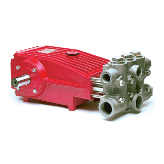
Triplex Ceramic
Plunger Pump
Operating Instructions/
Repair and Service
Manual
Contents:
Installation Instructions:
LP200-5100/LP121A-5100 Specs: page 3
Exploded View / Kits:
Parts List:
LP250-5100 Specs:
Repair Instructions:
Torque Specifications:
Pump Mounting Selection Guide:
Troubleshooting:
Recommended Spare Parts List:
Dimensions:
Warranty Information:
page 2
page 4
page 5
page 6
page 7-9
page 9
page 9
page 10
page 10
page 11
back page
Advertisement
Table of Contents

Related Manuals for Giant LP121A-5100


Summary of Contents for Giant LP121A-5100
- Page 1 Triplex Ceramic Plunger Pump Operating Instructions/ Repair and Service Models Manual LP121A-5100/LP200-5100/LP250-5100 Contents: Installation Instructions: page 2 LP200-5100/LP121A-5100 Specs: page 3 Exploded View / Kits: page 4 Parts List: page 5 LP250-5100 Specs: page 6 Repair Instructions: page 7-9 Torque Specifications:...
-
Page 2: Installation Instructions
It is the re- sponsibility of the equipment manufacturer and/or operator to ensure that all pertinent safety regulations are adhered to. NOTE: Contact Giant Industries for Service School Information. Phone: (419)-531-4600... - Page 3 Crankshaft Mounting ......................... Either Side Shaft Rotation ....................Top of Pulley Towards Fluid End Weight ..................119 lbs..........54 kg Crankshaft Diameter ..........................35 mm Model LP121A-5100 Specifications Metric Volume ..................32.5 GPM ........123.1 LPM Discharge Pressure ..............1740 PSI ..........120 Bar Inlet Pressure ................
- Page 4 Exploded View - LP121A-5100, LP200-5100, and LP250-5100 Important! The stainless steel valve plugs (48) can seize when being screwed out of the casing. To release tension beforehand, strike the plugs 1-2 times with a steel hammer on the top before...
-
Page 5: Parts List
LP121A-5100, LP200-5100, and LP250-5100 Parts List ITEM PART DESCRIPTION ITEM PART DESCRIPTION 07759 Crankcase 13228 Leakage Seal (LP200) 13000 Oil filler Plug Assembly 13360 Leakage Seal (LP250) 05940 Cover Plate 13291 Leakage Seal (LP121A) 07223-0100 Spring Ring 07170-0100 Seal Case (LP200, LP250) - Page 6 Specifications Model LP250-5100 U.S. Metric Volume .................26.0 GPM ......98.3 LPM Discharge Pressure 2200 PSI 150 Bar ....................Inlet Pressure -4.35 to 87 PSI ..-0.3 to 6.0 Bar ................Speed ..........................1000 RPM Plunger Diameter ..............1.26” ........32 mm Stroke ...................1.65” ........42 mm Crankcase Oil Capacity 118 fl.oz.
- Page 7 LP121A-5100, LP200-5100, and LP250-5100 - Repair Instructions 2. Remove the compression 3. Remove the complete 1. With a 30mm wrench, spring (45), O-rings and valve assembly (46A-46D) remove the 3 plugs (48). support rings (44A & 44B). with valve pullers.
- Page 8 LP121A-5100, LP200-5100, and LP250-5100 - Repair Instructions 38/38A 8. Remove seal case (37) 9. Check plunger surface (29B). If plunger pipe is worn, loos- from valve casing (43) en tension screws (29C) and pull off plunger pipe to the and inspect O-rings (38/38A).
-
Page 9: Repair Instructions
0.1mm and maximum 0.15mm by placing fitting discs (20A and 20B) under the bearing cover. IMPORTANT! After assembly has been completed, the crankshaft should turn easily with very little clearance. Tighten connecting rod screws (24A) to 22 ft.-lbs. (30 NM). LP121A-5100, LP200-5100, and LP250-5100 Torque Specifications Pos. Item # Description... -
Page 10: Recommended Spare Parts List
Replace plungers Inlet pressure too high Reduce inlet pressure High Crankcase Wrong Grade of oil Giant oil is recommended Temperature Improper amount of oil in crankcase Adjust oil level to proper amount Preventative Maintenance Check List & Recommended Spare Parts List... -
Page 11: Dimensions
LP121A-5100, LP200-5100, and LP250-5100 Dimensions - mm (in) - Page 12 A Returned Goods Authorization (R.G.A.) number and completed warranty evaluation form is required prior to the return to Giant Industries of all prod- ucts under warranty consideration. Call (419)-531-4600 or fax (419)-531-6836 to obtain an R.G.A.