
Related Manuals for abem Terrameter SAS 4000


Summary of Contents for abem Terrameter SAS 4000
- Page 1 __________________________________________________ Instruction Manual Terrameter SAS 4000 / SAS 1000 ABEM Product Number 33 0020 26 ABEM Printed Matter GGEO-100049 2018-08-28...
- Page 2 Information in this document is subject to change without notice and constitutes no commitment by ABEM Instrument AB. ABEM Instrument AB takes no responsibility for errors in the document or problems that may arise from the use of this material.
- Page 3 ABEM Terrameter SAS 1000 / SAS 4000 WARNING! Deadly hazard! The ABEM Terrameter SAS 4000 / SAS 1000 delivers high voltages and currents. Always consider all cables and electrodes connected directly or indirectly to the Terrameter to carry current. Stay away from cables and electrodes while the system is operating.
- Page 4 ABEM Terrameter SAS 1000 / SAS 4000 INTRODUCTION NPACKING AND NSPECTING 1.1.1 HIPPING DAMAGE CLAIMS ARRANTY EPACKING AND HIPPING OMPLIANCE GENERAL TERRAMETER SAS 4000 - T HE SYSTEM SAS 1000 – T ERRAMETER YSTEM SAS 1000 / 4000 - G...
- Page 5 ABEM Terrameter SAS 1000 / SAS 4000 CQUISITION TIMER POWER SUPPLY BATTERY PACK Safety precautions EXTERNAL V BATTERY DAPTER ELECTRODES AND CABLES ELECTRODES 5.1.1 TEEL LECTRODES 5.1.2 POLARISABLE LECTRODES 5.1.3 MPORTANT REMARKS CONCERNING CURRENT ELECTRODES CABLE SETS LUND IMAGING SYSTEM TRODUCTION 6.1.1...
- Page 6 ABEM Terrameter SAS 1000 / SAS 4000 Proceed as follows: IP L ESISTIVITY AND OGGING ESISTIVITY AND MODES ARE EXPLAINED BELOW SHORT NORMAL LOGGING LONG NORMAL LOGGING LATERAL LOGGING LUID ESISTIVITY AND STIMATION OF Concentrations by weight LOTTING OF OGGING...
- Page 7 ABEM Terrameter SAS 1000 / SAS 4000 9.5.2 SAS 1000 / 4000 UICK CHECK OF LUND TESTING OF EQUIPMENT 9.6.1 AST CONTINUITY TEST OF CABLE AND RELAY SWITCH “T ” 9.6.2 PECIAL CHECKS IN THE MODULE OFTWARE Check Cable Isolation.
- Page 8 ABEM Terrameter SAS 1000 / SAS 4000 14.6 DIPDIP4L + DIPDIP4S: 4-C CVES HANNEL IPOLE DIPOLE RRAY WITH LECTRODE ABLES 14.7 DIP4L + POLDIP4S: 4-C CVES HANNEL POLE DIPOLE RRAY WITH LECTRODE ABLES 14.8 GRAD3L6 + GRAD3S6: 3-C CVES HANNEL...
- Page 9 ABEM Terrameter SAS 1000 / SAS 4000 APPENDIX H. ERIGRAPH FILE FORMATS 17.1 NTRODUCTION 17.2 SEUDOSECTION LOTTING AND ORMAT 17.3 NVERTED ODEL LOTTING AND ORMAT 17.4 OPOGRAPHY 17.5 EFINED 17.6 EVEL ARKERS 17.7 EFERENCE APPENDIX I. TECHNICAL SPECIFICATIONS 18.1 TERRAMETER SAS 1000 / 4000 - SPECIFICATIONS 18.2...
- Page 10 ABEM Terrameter SAS 1000 / SAS 4000 STI I , mult , N mode On/Off 0(index) 19.2.11 OPM mode 19.2.12 ESISTIVITY STR I mode 19.2.13 STS t 19.2.14 TACK SAS N , Norm limit 19.2.15 OUND SND freq, freq, freq....
- Page 11 IMPORTANT It is important that you as a user of the instrument notify ABEM about your name and address. This allows us to keep you updated with important information about the instrument and e.g. upgrades of the built-in software and documentation. Please send your name and address directly to ABEM, utilize the Warranty Registration Card delivered along with the instrument.
- Page 12 ABEM's satisfaction to be defective. If misuse or abnormal conditions have caused the fault, repairs will be invoiced at cost. Should a fault occur that is not correctable on site, please send full details to ABEM. It is essential that instrument type and serial number is included and, if possible, the original ABEM delivery number.
- Page 13 The Terrameter SAS system consists of a basic unit called the Terrameter SAS 1000 or SAS 4000 which can be supplemented as desired with accessories such as the ABEM LUND electrode systems and the ABEM SAS LOG 300 borehole logging unit. This manual covers the operation of SAS 1000 and SAS 4000 as well as these accessories.
- Page 14 ABEM Terrameter SAS 1000 / SAS 4000 2.1 TERRAMETER SAS 4000 - THE SYSTEM The Terrameter SAS 4000 system consist of the following components: • SAS 4000 instrument with four input channels, including clip-on battery tray • External Battery Connector •...
- Page 15 ABEM Terrameter SAS 1000 / SAS 4000 Moreover, it can be used in a wide variety of applications where effective signal/noise discrimination is needed. It can be used to determine the ground resistance of grounding arrangements at power plants and along power lines and (in a pinch) it can even be used as an ohmmeter. The strength of the SAS 1000 / 4000 is its ability - thanks to the induced polarization mode - to distinguish between geological formations with identical resistivity, e.g.
- Page 16 ABEM Terrameter SAS 1000 / SAS 4000 Period Voltage Current Receiving intervals Figure 1. Timing diagram of the Terrameter SAS 1000 / 4000 in resistivity mode. The full- drawn curve shows the transmitted current, and the dotted curve an example of the measured voltage in the presence of noise.
- Page 17 ABEM Terrameter SAS 1000 / SAS 4000 Period Voltage Current Measuring intervals Figure 2. Timing diagram of the Terrameter SAS 1000 / 4000 in IP mode. The full-drawn curve shows the transmitted current, and the dotted curve an example of the measured decaying voltage in the presence of noise.
- Page 18 ABEM Terrameter SAS 1000 / SAS 4000 Window number (incremental factor = 1) 1000 1000 1000 1000 1000 1000 1000 1000 Table 2-2: The length of each of the time window (measured in msec) when the incremental factor is 1. The * indicates that in countries with 60Hz power line frequency, the value is 16.67 msec in stead of 20 msec.
- Page 19 ABEM Terrameter SAS 1000 / SAS 4000 Whenever the sum of the time windows in use exceeds the current on (off) time T, this time is extended so that the current off time exceeds the sum of the active time windows plus the initial time delay.
- Page 20 ABEM Terrameter SAS 1000 / SAS 4000 Exponential decay curve with added harmonic voltage (50 Hz, 10V) and normal distributed noise (StDev=10V) Time window Time [msec] Figure 4. Synthetic example illustrating the noise reduction effect in the chargeability. In this example the difference between the chargeabilities M...
- Page 21 ABEM Terrameter SAS 1000 / SAS 4000 layers. This (paradoxical) behaviour is explained quantitatively in the literature . Near-surface objects can also cause negative IP readings, see e.g. Principles of Applied Geophysics section 5.6. 2.4.4 DC potential measurement (SP) If the SP option is chosen in the Main Menu, DC potential (self-potential) measurements can be done.
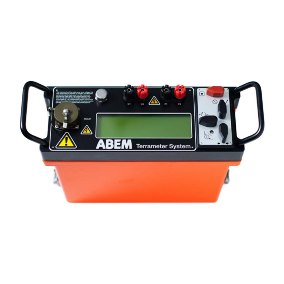
- Page 22 ABEM Terrameter SAS 1000 / SAS 4000 Figure 5: The Terrameter panel with display (centre), control knobs (right), multi purpose communication and signal connector (left), and current and potential terminals (top). On older SAS 4000 instruments there may be additional communication connectors.
- Page 23 ABEM Terrameter SAS 1000 / SAS 4000 • Robust data-acquisition software featuring: • Automatic measurement process. • Automatic roll-along with coordinate updating. • Electrode cable geometry and switching sequence defined in address and protocol files allow user-defined surveying strategies and arrays. Files are supplied for Wenner, Wenner-Schlumberger, multiple gradient array, pole-dipole, dipole-dipole, pole-pole and square-array measurements.
- Page 24 ABEM Terrameter SAS 1000 / SAS 4000 3 OPERATING THE SAS 1000 / 4000 These operating instructions explain only how to handle the equipment itself. Instructions for conducting the different types of surveys are available in other documents. 3.1 CONTROLS AND TERMINALS 3.1.1 Controls...
- Page 25 ABEM Terrameter SAS 1000 / SAS 4000 ╔═Measure para[RES:R00001] (│)Page 1/6═╗ ║Output: 200 mA Mode: Auto ║ ║Acq. delay╔═══════════════╗ ║ ║Acq. time:║Power off? ║ ║ ║ ║<Ok> <Cancel> ║ ║ ║Total cycl╚═══════════════╝. ║ ║ ║ ╚( )=Measure ()=Quit════════════════╝ Keeping the two knobs towards each other for an extended period of time, will cut the instrument power regardless computer activities, data and settings may not be saved.
- Page 26 ABEM Terrameter SAS 1000 / SAS 4000 The Multi Channel Adapter is used to connect more than one potential channel in e.g. vertical electrical soundings. In performing Schlumberger soundings it is very favourable to connect the four channels to potential electrodes separated by, say, 0.20 m, 1 m, 3 m and 10 m. Then the overlapping sounding curve segments, needed in Schlumberger soundings, are easily constructed afterwards.
- Page 27 ABEM Terrameter SAS 1000 / SAS 4000 3.2 WARNINGS 3.2.1 Safety Dangerous voltages and currents are transmitted by the Terrameter via the cables and electrodes connected to it! During the entire duration of an electrode contact test or measurement session it is the responsibility of the operator always to have full...
- Page 28 ABEM Terrameter SAS 1000 / SAS 4000 bags filled with a salt with high thermal capacity that can be placed in contact with the sides of the instrument. Another option under extreme climate conditions is to lean the instrument and place a moist piece of cloth on the side of it;...
- Page 29 ABEM Terrameter SAS 1000 / SAS 4000 ╔══════════(Res.) R00002.S4K═══════════╗ By selecting a new record the next menu ║Method: Untitled ║ appears. For VES with pre-defined protocols ║Layout: Untitled ║ ║No of channels: ║ (see below) set “Layout:” to “Sounding”, and ║Powerline freq.: 50 Hz...
- Page 30 ABEM Terrameter SAS 1000 / SAS 4000 ╔═Select locat[RES:R00002] (±)Page 6/6═╗ It is possible to select pre-defined electrode ║ ║ geometries from a protocol file that has been ║ Select: ║ ║ ║ uploaded using the “Transfer/Install XYZ ║ ║...
- Page 31 • Position the SAS 1000 / 4000 half way between the potential electrodes (M and N). Connect terminals P1 and P2 to terminals M and N respectively. Use an ABEM sounding cable set or a 2-conductor cable of good quality with the conductors separated at the electrode end.
- Page 32 ABEM Terrameter SAS 1000 / SAS 4000 3.4.4 Induced Polarization surveys It is preferable to use non-polarisable electrodes for the potential electrodes. However, stainless steel electrodes will work fine in many cases, even though the noise level is increased considerably. For IP soundings perform as described above in section 3.4.3, with the exception that you have to select IP mode instead of Resistivity.
- Page 33 ABEM Terrameter SAS 1000 / SAS 4000 3.5 ACQUISITION TIMER In all measurement modes (resistivity, IP and SP) and in as well standard measurements as LUND measurements, a timer function can be activated. This timer will automatically start a measurement at certain time intervals.
-
Page 34: Power Supply
ABEM Terrameter SAS 1000 / SAS 4000 4 POWER SUPPLY The SAS 4000 is powered by either by a clip-on NiMH (NiCd for older units) battery pack or by an external 12V source. The SAS 1000 / 4000 consumes around 1000 mA whenever it is turned on. - Page 35 ABEM Terrameter SAS 1000 / SAS 4000 4.2 EXTERNAL 12 V BATTERY ADAPTER The external battery adapter was delivered together with your Terrameter SAS 1000 / 4000. When you need more power than available in the standard battery pack, the external battery adapter is a convenient solution.
- Page 36 5.1.2 Non-polarisable Electrodes Self potential surveys require non-polarisable electrodes. Also Induced Polarization soundings are preferably measured with non-polarisable electrodes. The ABEM Terrameter type of electrode consists of a solid state gypsum rod, covered with a plastic cylinder. The gypsum contains lead-chloride (PbCl ), and a solid lead rod is placed in the centre.
- Page 37 ABEM Terrameter SAS 1000 / SAS 4000 Self-potentials recorded at Lund University - 2000-10-30 Steel electrodes 50 cm spacing between the electrodes Pb-PbCl electrodes 1000 2000 3000 4000 Time (s) Figure 7. Potentials measured between a pair of Pb-PbCl electrodes (lower curve) and a pair of steel electrodes (upper curve), showing typical difference in electrode noise.
- Page 38 ABEM Terrameter SAS 1000 / SAS 4000 Resistance in between electrode and soil 1000 Soil resistivity: 100 Ohm-m Electrode diameter: 1 cm Electrode burial in ground [m] Figure 8. Theoretical relation between electrode burial and the contact resistance. 5.2 CABLE SETS The standard Schlumberger and Wenner sounding cable set consists of 2 x 750 m current cable, 0.75 mm...
- Page 39 To ensure you get optimum results with ABEM Lund Imaging System, please take time to read this Reference Manual thoroughly. It gives you detailed step-by-step instructions for cost-effective field measurements.
- Page 40 ABEM Terrameter SAS 1000 / SAS 4000 become familiar with its layout and contents. If you should, for any reason, have difficulties in operating ABEM Lund Imaging System or in getting satisfactory resistivity survey results, please contact your authorised ABEM distributor. ABEM always listens to end-user comments about their experience with ABEM products.
- Page 41 ABEM Terrameter SAS 1000 / SAS 4000 Figure 9. Sketch system layout for roll-along CVES surveying using four electrode cables. With 2 meter intervals between the electrode take-outs the system has a total length of 160 meter, with 5 meter intervals the total length is 400 meters.
- Page 42 • To ensure proper function, SAS 1000 / 4000 should be powered from a gelled lead-acid battery or a car battery (25 – 70 Ah). • ABEM Electrode Selector ES 464 / ES 10-64e / ES 10-64, including connecting cable to Terrameter. • Lund spread cables and suitable quantity of Cable Joints and cable jumpers.
- Page 43 To ensure proper function, SAS 1000 / 4000 should be powered from a gelled lead- acid battery or a car battery of sufficient capacity. The following field procedure assumes that the standard ABEM Lund equipment with a set of 4 cables with 21 electrode take-outs each is used.
- Page 44 ABEM Terrameter SAS 1000 / SAS 4000 Figure 10. Cable arrangement at the first measurement station in a roll-along survey, where the first cable is excluded. All CVES cables shall be rolled out in the direction of the profile, i.e. with the takeout numbers increasing in the same direction as the coordinate numbers increase.
- Page 45 ABEM Terrameter SAS 1000 / SAS 4000 Note! Moisture and/or dirt in the connectors may compromise the data quality and even cause permanent damage to the connectors. Always keep the protection caps clean and in place whenever possible. Let the protection caps protect each other when the cables are connected as shown in the picture.
- Page 46 ABEM Terrameter SAS 1000 / SAS 4000 Figure 12. Cable arrangement at the last measurement station in a Wenner, Schlumberger or multiple gradient array roll-along survey, where the last cable is excluded. If the multi-channel dipole-dipole or pole-dipole protocols mentioned in this document are used, it is necessary to do roll-along twice without adding new cable at end of line (see Figure 13).
- Page 47 ABEM Terrameter SAS 1000 / SAS 4000 6.2.5 Using the LUND Imaging System Software In the start-up menu select "LUND Imaging System" and press . This starts the LUND program as described in the following. ╔════════════RECORD MANAGER════════════╗ The first menu (after the welcome menu) is the ║Mode:...
- Page 48 A typical selection for one channel measurement is WENNER_L and WENNER_S, which is optimised for use together with the standard ABEM LUND cable, article no. 33 0019 25 or 33 0019 26. For four channel measurements the combination GRAD4L8 GRAD4S8 recommended.
- Page 49 ABEM Terrameter SAS 1000 / SAS 4000 ╔══Resistivity: LR00004.S4K (PAGE/±) ══╗ In the fourth submenu you decide whether or not ║Ignore negative resistivity: ║ to ignore negative readings and errors. You can ║Ignore errors 1-5: ║ ║Wait between protocols: ║...
- Page 50 ABEM Terrameter SAS 1000 / SAS 4000 Resistance S.Dev Stacks. To accept, press the (or select the <START> option). This start the electrode test (if you have 2: N/A 3: N/A selected "Electrode test: Yes" above) or the 4: N/A...
- Page 51 ABEM Terrameter SAS 1000 / SAS 4000 6.2.7 Speed Up the Field Procedure A good way to speed up the field procedure is to have one extra electrode cable and a generous supply of electrode and cable jumpers available, so that the extra cable can be rolled out and hooked up to electrodes while measurements are in progress.
- Page 52 ABEM Terrameter SAS 1000 / SAS 4000 (down), but the cables must always be rolled out with increasing takeout numbers in parallel with increasing coordinate numbers. 6.2.8 Data Cover The data cover for resistivity surveying with cable systems in general is dependent on several factors such as: the total number of electrode take-outs, the number of sections the cable array is divided into, the measurement array type used (Wenner, pole-pole, dipole-dipole etc.), and...
- Page 53 ABEM Terrameter SAS 1000 / SAS 4000 6.2.9 Area Cover / 3D Roll-along For applications where area coverage is needed it may be desirable to do roll-along in a direction perpendicular to the extension of the cables, as shown in Figure 15.
- Page 54 ABEM Terrameter SAS 1000 / SAS 4000 Line 9 Start Line 8 Start Line 7 Start Line 6 Start Line 5 Start Line 4 Start Line 3 Start Line 2 Start Line 1 Start X axis Figure 16. Example showing a survey consisting of 9 parallel lines oriented in the x-direction.
- Page 55 ABEM Terrameter SAS 1000 / SAS 4000 particular hardware configuration of these cables, and protocol files should use array code 12 (tomography). See section 8.1.5 “Format of Lund Imaging Address, Protocol and Location Files” (page 60) for more information on address and protocol files. The roll-along feature will not work for this type of measurements.
- Page 56 ABEM Terrameter SAS 1000 / SAS 4000 Unstable Poor electrode Check that the Terrameter is set to as high possibly negative connection/grounding, and measuring current possible! readings possibly too low measuring necessary water, and hammer down, current. High level of self- electrodes, and if that is not sufficient potential.
- Page 57 A control cable, 33 0020 11, connects the SAS LOG 300 to SAS 1000 / 4000. The SAS LOG is fully governed from the SAS 1000 / 4000. The return current terminal is connected to a return current electrode (ABEM stainless steel electrode) placed not less than 75 m from the well to be surveyed.
- Page 58 ABEM Terrameter SAS 1000 / SAS 4000 • Long Normal (Resistivity) • Lateral (Resistivity) • Fluid Resistivity (Resistivity) • Short Normal IP • Long Normal IP • Lateral IP 7.2 OPERATING THE LOGGING SYSTEM Assuming basic familiarity with SAS 1000 / 4000, these would be the steps to set up for a well logging 1.
- Page 59 ABEM Terrameter SAS 1000 / SAS 4000 WARNING: Make certain that Terrameter SAS 1000 / 4000 is turned off while handling the logging cable and probe. The cable and probe electrodes can carry high voltages after the MEASURE button on the SAS 1000 / 4000 is activated.
- Page 60 ABEM Terrameter SAS 1000 / SAS 4000 7.3 TEMPERATURE & SP LOGGING Normally temperature and SP are logged at the first run downwards the well, in the unstirred water and with no polarization effects residing from resistivity measurements. 5.6 m The temperature is measured to an accuracy of 1C within the...
- Page 61 ABEM Terrameter SAS 1000 / SAS 4000 7.4 RESISTIVITY AND IP LOGGING N. B. Resistivity or IP measurements should not be made during a SP logging run. • Select Up • Enter the actual depth in, meters, where the upwards resistivity logging should commence.
- Page 62 7.7 PLOTTING OF LOGGING DATA The most commonly used data format for borehole is LAS (Log ASCII Standard). The Terrameter SAS 4000 / SAS 1000 Utilities software has an option to convert logging data from S4K raw data files to LAS format.
- Page 63 ABEM Terrameter SAS 1000 / SAS 4000 A general purpose diagram plotting software (e.g. Grapher or Excel) can be used for the plotting. This may require some editing of the data file, like e.g. simply removing the part of the file before the data section. Another option is to use Interpex IX1D.
- Page 64 The utility software for Windows 95/98/NT/ME/2000/XP is delivered on CD. You can also download the most recent version of the software from http://www.abem.se. Insert the CD in your computer, and execute the SETUP program to install the software. By default the software is installed in the directory C:\SAS 4000.
- Page 65 1000 / 4000 will be damaged, and you have lost all possibilities to communicate with the SAS 1000 / 4000. If this happens you will need to ship the SAS 1000 / 4000 to ABEM for new program installation. Also ensure there is sufficient battery capacity before starting upgrading the communication program.
- Page 66 ABEM Terrameter SAS 1000 / SAS 4000 8.1.2 Data Conversion Observe, that the files residing on the Terrameter are saved in a binary format with the file extension .S4K. It is therefore necessary to convert the data files to another convenient format.
- Page 67 ABEM Terrameter SAS 1000 / SAS 4000 You can add as many files you want. Some basic information about each file is given, e.g. measuring data and instrument serial number. To convert the files, mark them and right-click (or simply click the ! tool or press the F8 key) to convert.
- Page 68 ABEM Terrameter SAS 1000 / SAS 4000 The "-r" option means conversion to RES2DINV format, which is also accepted by ERIGRAPH. In this example all LUND resistivity files are converted due to the file name LR*.S4K. (Refer to Appendix F. S4KCONV for information about this command.) 8.1.4 Measurement Protocol Generation and Management...
- Page 69 ABEM Terrameter SAS 1000 / SAS 4000 The leftmost “Manage Protocols” brings up the dialog box: Among the available protocols (left) you can select which protocols to make active. Press OK to finish. In the above example only two protocols are selected. To compile these protocols into a binary file PROTOCOL.BIN, press the rightmost tool.
- Page 70 ABEM Terrameter SAS 1000 / SAS 4000 For example, if only an ORG-file has been created and no UP- and DWN-files a warning will be issued. As it is fully legal to define only an ORG-file the compiler accepts this but warns the user that he/she might have missed to supply the UP- and DWN-files.
- Page 71 ABEM Terrameter SAS 1000 / SAS 4000 ntot adr cable -pos { number, internal address and physical position of last take-out } ntot ntot ntot For line oriented cable arrangements with roll-along in the direction of the cable the parameters...
- Page 72 ABEM Terrameter SAS 1000 / SAS 4000 where the electrode positions are given as integers in the interval 1-n . If remote electrodes are used these positions are specified as zero. Example protocol files can be found in “Example Protocol Files” (page 92).
- Page 73 ABEM Terrameter SAS 1000 / SAS 4000 8.1.6 Format of VES Protocol Files The electrode geometry for VES can be pre-defined via measurement protocols defined via a textfile saved with XYZ file extension (the filename must have maximum 8 characters). The...
- Page 74 ABEM Terrameter SAS 1000 / SAS 4000 8.2 ERIGRAPH The software ERIGRAPH is primarily designed to facilitate graphical presentation of CVES (2D electrical imaging) data and associated inverted model sections. The measured apparent resistivity can be plotted as pseudosections in colour or grey scale. Inverted sections can be plotted as continuous (smooth) plots or as rectangular blocks.
- Page 75 ABEM Terrameter SAS 1000 / SAS 4000 If the topography is not included in the DAT file by the conversion routine it can be manually copied into the data file in the regular format after the resistivity data, but a line with the text “Topography in separate list”...
- Page 76 ABEM Terrameter SAS 1000 / SAS 4000 The selection of resistivity interval limits is of major importance when presenting data, as the perception of the plotted data is strongly controlled by the colours. A suitable selection of limits may enhance the geological variation, while an unsuitable selection may hide important information or enhance irrelevant features.
- Page 77 Two such examples of programs are RES2DINV, SENS2DINV and RESIX 2DI, which perform smoothness-constrained inversion (inverse modelling). Please ask ABEM or your authorised ABEM Distributor for details about resistivity interpretation packages that are available. For inverting the data with RES2DINV transfer the S4K files to a computer in the regular way via the SAS1000/4000 Utility Software or use ERIGRAPH (version 2.9 or higher) for the...
- Page 78 ABEM Terrameter SAS 1000 / SAS 4000 Figure 19. Example of an inverted 2D section. 8.2.4 Data Quality Checking and Editing ERIGRAPH can be used for a visual data quality assessment, and it is recommended to plot data for each n-factor or each electrode spacing separately, or it may appear as the example in Figure 20.
- Page 79 ABEM Terrameter SAS 1000 / SAS 4000 Example of RES2DINV “Edit bad data” plot of multiple gradient array data. Figure 21. Another way to deal with data quality is to start running a preliminary inversion using the robust inversion method. The function “Display/Edit data/Estimate data errors” can then be used to save the data with estimates of the measurement errors, which are based on the model residuals from the inversion.
-
Page 80: Error Codes
ABEM Terrameter SAS 1000 / SAS 4000 9 SERVICING THE EQUIPMENT The Terrameter SAS System is designed to withstand the normal wear and tear encountered in field work. 9.1 GENERAL PRECAUTIONS Excessive vibration, temperature and moisture exposure should be avoided: •... - Page 81 ABEM Terrameter SAS 1000 / SAS 4000 9.5 PERIODIC CHECKS 9.5.1 Terrameter SAS 1000 / 4000 - Check The proper functioning of most of the SAS 1000 / 4000 circuitry can be checked using reference resistors and a capacitor having known values. This test should be performed at least once per year.
- Page 82 ABEM Terrameter SAS 1000 / SAS 4000 Deviations from the expected values of up to 10% are acceptable, because the components only have a limited accuracy. Usually the chargeability reading M is in the range 8.0 to 10,110 8.5 msec.
- Page 83 ABEM Terrameter SAS 1000 / SAS 4000 9.6 TESTING OF LUND EQUIPMENT 9.6.1 Fast continuity test of cable and relay switch Figure 22. Connecting both ends of one LUND cable to the ES464 / ES10-64(e). It is possible to test each of the 32 conductors in a LUND cable by use of the ordinary LUND program module, using a special protocol file.
- Page 84 ABEM Terrameter SAS 1000 / SAS 4000 8. The resulting .S4K file can be converted to an AMP file for documentation. An example of such an .AMP file is shown below. _________________________________________________________________________________________________ Filename: D:\SAS 4000\Data\lrtest02.s4k Instrument ID: SAS 1000 2001336 Date &...
- Page 85 ABEM Terrameter SAS 1000 / SAS 4000 9.6.3 Terrameter SAS LOG 300 - Checks A full check of the SAS LOG 300 is quite complicated and must be done in the ABEM laboratory. However, the thermometer and the fluid resistivity cell can be checked fairly accurately using a fluid of known temperature and resistivity in a suitable container.
- Page 86 ABEM Terrameter SAS 1000 / SAS 4000 10 APPENDIX BASIC PRINCIPLES RESISTIVITY SURVEYING 10.1 GENERAL The SAS 1000 / 4000 measures different parameters that characterizes the ground: • Resistivity • Induced Polarization • Self Potential The electrical resistivity varies between different geological materials, dependent mainly on variations in water contents and dissolved ions in the water.
- Page 87 ABEM Terrameter SAS 1000 / SAS 4000 Figure 23. Typical ranges of electric resistivities of geological materials. The amount of water in a material depends on the porosity, which may be divided into primary and secondary porosity. Primary porosity consists of pore spaces between the mineral particles, and occurs in soils and sedimentary rocks.
- Page 88 ABEM Terrameter SAS 1000 / SAS 4000 The presence of clay minerals strongly affects the resistivity of sediments and weathered rock. The clay minerals may be regarded as electrically conductive particles, which can absorb and release ions and water molecules on its surface through an ion exchange process.
- Page 89 ABEM Terrameter SAS 1000 / SAS 4000 In homogeneous ground the apparent resistivity will equal the true resistivity, but will normally be a combination of all contributing strata. Thus, the geometrically corrected quantity is called apparent resistivity ( Figure 25 shows examples of different collinear electrode configurations in use: Wenner (, ...
- Page 90 ABEM Terrameter SAS 1000 / SAS 4000 10.2 MULTIPLE GRADIENT ARRAY SURVEYING The following text is mainly based on Dahlin and Zhou (2002). 10.2.1 Surveying Principles Multi-electrode gradient surveying is carried out by injecting current with a separation (s+2)a and simultaneously or sequentially picking up all the potential differences between the potential electrodes with the spacing a (Figure 1).
- Page 91 ABEM Terrameter SAS 1000 / SAS 4000 Gradient array (s+2)a P1 P2 P1 P2 Figure 27. Schematic representations for a) gradient array, b) pole-dipole, and c) Schlumberger measurement. The background shows the sensitivity pattern of the configuration, in the gradient case for the first potential electrode pair (n-factor = 1).
- Page 92 ABEM Terrameter SAS 1000 / SAS 4000 Reynolds, J.M. (1997) An Introduction to Applied and Environmental Geophysics, ISBN 0- 471-95555-8, John Wiley and Sons, Chicester, 796p. Sharma, P.V. (1997) Environmental and Engineering Geophysics, ISBN 0 521 57632 6, Cambridge University Press, 475p.
- Page 93 ABEM Terrameter SAS 1000 / SAS 4000 11 APPENDIX B. TERRAMETER ERROR CODES Whenever an error occurs in the Terrameter SAS 1000 / 4000 a code is displayed on the screen. The meaning of the codes is as follows: Error code Cause...
- Page 94 ABEM Terrameter SAS 1000 / SAS 4000 Internal error invalid setup Try again. If the error persists, contact parameters ABEM. Internal error - invalid fundamental Try again. If the error persists, contact frequency ABEM. Record full No more readings can be added to this record.
- Page 95 ABEM Terrameter SAS 1000 / SAS 4000 Multimac general error More than one electrode connected Check the electrode switcher(s) Connection error Multimac No electrodes at all connected Quit Multimac measurement The addressed Multimac electrode does not exist user defined protocol...
- Page 96 ABEM Terrameter SAS 1000 / SAS 4000 12 APPENDIX C. MPFC ERROR CODES There are a number of error codes associated with the MPFC.EXE program, as listed below. Errors are fatal and cause no database file to be created while warnings are non-fatal and a database file will be created.
- Page 97 ABEM Terrameter SAS 1000 / SAS 4000 3102 One of n or n must be zero. The layout can only be moved x-move y-move in either the X- or Y-direction. 3201 Could not open a .MM file 3202 Could not find the referred geometry file .XYZ...
- Page 98 ABEM Terrameter SAS 1000 / SAS 4000 13 APPENDIX D. ES464 / ES10-64 ADDRESS, TAKE- OUT AND PIN CONNECTOR RELATION The following table describes the connection between the address, the cable take out and the pin in the connectors when using all three connectors (left) or only the two connectors (right).
- Page 99 ABEM Terrameter SAS 1000 / SAS 4000 - 89 -...
- Page 100 ABEM Terrameter SAS 1000 / SAS 4000 14 APPENDIX E. ADDRESS AND PROTOCOL FILES 14.1 EXAMPLE ADDRESS FILES Example Address Files for CVES The following file (LONG32.ADR) is used when four electrode cables are arranged on a line and linked together to the Electrode Selector, used for roll-along in the direction of the cable layout.
- Page 101 ABEM Terrameter SAS 1000 / SAS 4000 2-11 2-12 2-13 2-14 2-15 2-16 2-17 2-18 2-19 2-20 2-21 3-10 3-11 3-12 3-13 3-14 3-15 3-16 3-17 3-18 3-19 3-20 3-21 Example Address Files for Areal/3D Cover For roll-along perpendicular to the direction of cable extension a little additional information is needed, specifying that cables are moved for roll-along in the y-direction instead and the number of take-outs in x-direction.
- Page 102 ABEM Terrameter SAS 1000 / SAS 4000 2-13 2-14 2-15 2-16 2-17 2-18 2-19 2-20 2-21 3-10 3-11 3-12 3-13 3-14 3-15 3-16 3-17 3-18 3-19 3-20 3-21 14.2 EXAMPLE PROTOCOL FILES Example: Wenner Array Protocol File The following example is extracted from a protocol file used for Wenner CVES (single...
- Page 103 ABEM Terrameter SAS 1000 / SAS 4000 Example: Gradient Array Protocol File The following example is extracted from a protocol file used for 4-channel multiple gradient array CVES: GRADIENT LONG Gradient array for 4 channel measuring w. SAS4000 + ES10-64...
- Page 104 ABEM Terrameter SAS 1000 / SAS 4000 14.3 EXAMPLE LOCATION / GEOMETRY FILE The electrode coordinates for a borehole measurement are entered via a location or geometry file (textfile with LOC or XYZ file extension). Here is an example: Surface cable...
- Page 105 ABEM Terrameter SAS 1000 / SAS 4000 The following pages describe example protocol files supplied with the Lund Imaging System. - 95 -...
- Page 106 ABEM Terrameter SAS 1000 / SAS 4000 14.4 WENNER_L + WENNER_S: 1-CHANNEL WENNER CVES WITH 4 ELECTRODE CABLES This combination of protocol files is intended for Wenner- CVES roll-along measurements, and has been found very useful for a variety of applications. Note that it is important to select the protocol files in the correct order, starting with the long layout (WENNER_L) before selecting the protocol for short layout (WENNER_S).
- Page 107 ABEM Terrameter SAS 1000 / SAS 4000 14.5 GRAD4L(X)8 + GRAD4S8: 4-CHANNEL MULTIPLE GRADIENT ARRAY CVES WITH 4 ELECTRODE CABLES This combination of protocol files is intended for multiple gradient array CVES roll-along measurements, and has been found very useful for a variety of applications. It offers a...
- Page 108 ABEM Terrameter SAS 1000 / SAS 4000 14.6 DIPDIP4L + DIPDIP4S: 4-CHANNEL DIPOLE-DIPOLE ARRAY CVES WITH 4 ELECTRODE CABLES This combination of protocol files is intended for dipole-dipole array CVES roll-along measurements, and has been found very useful for a variety of applications. It offers a...
- Page 109 ABEM Terrameter SAS 1000 / SAS 4000 14.7 POLDIP4L + POLDIP4S: 4-CHANNEL POLE-DIPOLE ARRAY CVES WITH 4 ELECTRODE CABLES + REMOTE ELECTRODE This combination of protocol files is intended for dipole-dipole array CVES roll-along measurements, and has been found very useful for a variety of applications. It offers a...
- Page 110 ABEM Terrameter SAS 1000 / SAS 4000 14.8 GRAD3L6 + GRAD3S6: 3-CHANNEL MULTIPLE GRADIENT ARRAY CVES WITH 4 ELECTRODE CABLES This combination of protocol files is intended for multiple gradient array CVES roll-along measurements, and has been found very useful for a variety of applications. It offers a...
- Page 111 ABEM Terrameter SAS 1000 / SAS 4000 14.9 GRAD1L7 + GRAD1S7: 1-CHANNEL MULTIPLE GRADIENT ARRAY CVES WITH 4 ELECTRODE CABLES This combination of protocol files is intended for multiple gradient array CVES roll-along measurements, and has been found very useful for a variety of applications. It offers a resolution superior to the commonly used Wenner array.
- Page 112 ABEM Terrameter SAS 1000 / SAS 4000 14.10 WEN32SX: 1-CHANNEL WENNER CVES WITH 2 ELECTRODE CABLES This protocol file is intended for Wenner- CVES roll-along measurements with 2 cables only, i.e. it is not reduced for long array overlap. Protocol Array Type Address File Size .ORG...
- Page 113 ABEM Terrameter SAS 1000 / SAS 4000 14.11 POL3SS: 3-CHANNEL POLE-POLE CVES WITH 2 ELECTRODE CABLES Please observe that C2 and P2 are the remote electrodes. This measurement protocol is designed for pole-pole CVES using only two standard cable sections, addressing each electrode take-out. The number of measurement combinations...
- Page 114 ABEM Terrameter SAS 1000 / SAS 4000 14.12 POL3L: 3-CHANNEL POLE-POLE CVES WITH 4 ELECTRODE CABLES Please observe that C2 and P2 are the remote electrodes. This measurement protocol is designed for pole-pole CVES using four standard cable sections linked together, addressing every fourth electrode take-out. The number of measurement...
- Page 115 ABEM Terrameter SAS 1000 / SAS 4000 14.13 SQUARE2A, SQUARE2B AND SQUARE2C: SQUARE ARRAY AREA COVER WITH TWO ELECTRODE SPACINGS These protocol files are intended for area cover with roll-along perpendicular to the layout direction of the cables. The roll-along direction can be in either direction depending on if a right handed or left handed coordinate system is preferred (often the opposite direction to as what is illustrated above is preferable).
- Page 116 ABEM Terrameter SAS 1000 / SAS 4000 14.14 POL8X8: POLE-POLE IN 8X8 SQUARE GRID Cable D Cable C Cable B Cable A Figure. Sketch of 8 x 8 electrode layout using 4 standard Lund cables with 21 take-outs each. The cables are connected so that take-out 1 is closest to the instrument. Note...
- Page 117 ABEM Terrameter SAS 1000 / SAS 4000 For 3D surveys, however, an 8x8 layout is very small. It is generally more convenient to carry out a 3D survey as a number of parallel, and possibly also perpendicular 2D lines that, may later be assembled to a 3D data set (see “3D Resistivity Surveying by Means of a Number of...
- Page 118 ABEM Terrameter SAS 1000 / SAS 4000 14.15 POL21X7A-F: 3 CHANNEL POLE-POLE 3D ROLL-ALONG SURVEYING These protocol files are intended for area cover with roll-along perpendicular to the layout direction of the cables, using the special adapter cable for 3 channel measurement using Terrameter SAS4000 and one unit ES464.
- Page 119 ABEM Terrameter SAS 1000 / SAS 4000 14.16 POLDIP_A AND POLDIP_O: 4 CHANNEL POLE-DIPOLE 2D TO 3D SURVEYING Line 9 Start Line 8 Start Line 7 Start Line 6 Start Line 5 Start Line 4 Start Line 3 Start Line 2...
- Page 120 -options wildcard @filename -F:type Convert data to ABEM Multi Purpose Format (ASCII-text). Output file extension: .AMP Convert data to ERIGRAPH format. Output file extension: .DAT Convert data to RES2DINV format. Output file extension: .DAT Convert data to Interpex RESIX IP format. Output file extension .RPD Convert data to Interpex RESIX Plus format.
- Page 121 ABEM Terrameter SAS 1000 / SAS 4000 -i:nn Use chargeability for interval nn only. Valid for IP records only. Sum chargeabilities of intervals mm to nn. If only one value is given, chargeabilities will be summed from interval 1 to nn.
- Page 122 ABEM Terrameter SAS 1000 / SAS 4000 15.4 ERROR CODES S4KCONV 1001 There is no support for converting this electrode layout 1002 There is no support for converting this type of data 1003 A general conversion error occurred 1004 Geometry file does not exist or is invalid...
- Page 123 16 APPENDIX G. AMP FILE FORMAT This is a description of the ABEM Multi-purpose Protocol data format contained in an ASCII text file. It is intended to be fairly complete, but has the potential to have items added in the future.
- Page 124 ABEM Terrameter SAS 1000 / SAS 4000 If the mode is 2R the data values are resistance values (measured in ohms) Line 7 Measurement method. This may be any suitable text describing how the data were acquired, preferably one word. For example: Section, Sounding etc.
- Page 125 ABEM Terrameter SAS 1000 / SAS 4000 to the right of the receiving dipole) this will be a negative number. For the Wenner array it is identical to the spacing multiplier index. For the Schlumberger array it is the number of electrode spacings between the outer and inner electrodes.
- Page 126 ABEM Terrameter SAS 1000 / SAS 4000 120- 121-~ 122-~ 123- ”Time” is the elapsed time in seconds between the creation of the original data record and the acquisition of the data point. ”Electrode positions” can be either in the Index-format or the XYZ-format described above.
- Page 127 ABEM Terrameter SAS 1000 / SAS 4000 Electrode Locations The data are given in a format that supports more than one co-ordinate set and missing electrodes. Each co-ordinate set is contained in its own section. If an electrode is missing, its co-ordinates are set to nan (=not a number) or a dash (-).
- Page 128 ABEM Terrameter SAS 1000 / SAS 4000 Table A: Available electrode layout codes, names and three-letter abbreviations. Code Name Three-letter Comment abbreviation Untitled This code is used for layouts that have not been defined or arbitrary layouts. See also code=11.
- Page 129 ABEM Terrameter SAS 1000 / SAS 4000 16.7 EXAMPLES Example A: An example of a data file containing IP data acquired using SAS 1000 / 4000 + ES464 LUND Filename: LI00003.S4K Instrument ID: SAS 4000 Date & Time: 05/05/1997 10:31:10...
- Page 130 ABEM Terrameter SAS 1000 / SAS 4000 Example B: Same as example a, but with XYZ-format instead of indexed co-ordinates. Filename: LI00003.S4K Instrument ID: SAS 4000 Date & Time: 05/05/1997 10:31:10 Base station: Rows header/data/topography: Acquistion mode: Measurement method: Section...
- Page 131 ABEM Terrameter SAS 1000 / SAS 4000 Example C: An example of a datafile containing resistivity data. Filename: LR00003.S4K Instrument ID: SAS 4000 Date & Time: 05/05/1997 12:57:33 Base station: Rows header/data/topography: Acquistion mode: Measurement method: Section Electrode layout: Wenner-a...
- Page 132 ABEM Terrameter SAS 1000 / SAS 4000 Example D: An example of a file with resistance instead of apparent resistivity data and with topography data included. Filename: LR00003.S4K Instrument ID: SAS 4000 Date & Time: 05/05/1997 12:57:33 Base station: Rows header/data/topography:...
- Page 133 Res2dinv (in both cases DAT filename extension is assumed). For the latter format please refer to the manual of Res2dinv. Field data files from the ABEM Lund Imaging System can be converted into DAT-files using ERIGRAPH or the Terrameter SAS1000 / SAS4000 Utility Software.
- Page 134 ABEM Terrameter SAS 4000 / SAS 1000 The specified depth is in this case be the midpoint of each layer. Blank model cells should be entered as asterisks (*). If IP data is available it can be included as indicated, the square parantheses [] indicate that it is optional.
- Page 135 ABEM Terrameter SAS 4000 / SAS 1000 then plot the associated 2D section since the RHO-1 model file does not contain any topography information. The RHO-2 format includes topography in the model file. 17.5 USER DEFINED TEXT The text strings on the axes of the diagrams can be customised by placing a text file in the directory holding the data files to be plotted.
-
Page 136: Reference Data
ABEM Terrameter SAS 4000 / SAS 1000 17.7 REFERENCE DATA Drilling reference data can be included in the model plots as well. x(1) / distance id(1) / reference point id text string (optional) gwl(1) / groundwater level (optional) / no of layers x(1,1) d(1,1) code(1,1) col(1,1) txt(1,1) / dist, depth, materialcode, textcolour, text lable x(1,2) d(1,2) code(1,2) col(1,2) txt(1,2)... - Page 137 ABEM Terrameter SAS 4000 / SAS 1000 18 APPENDIX I. TECHNICAL SPECIFICATIONS This section presents specifications for the Terrameter SAS 1000 / 4000, the Electrode Selector ES464 / ES10-64 / ES10-64E and the Terrameter SAS LOG 300. 18.1 TERRAMETER SAS 1000 / 4000 - SPECIFICATIONS...
- Page 138 ABEM Terrameter SAS 4000 / SAS 1000 Precision V/I Typically better than 0.5% (at 0.5 sec integration). Dynamic range Up to 140 dB plus 64 dB automatic gain Induced Polarization (IP) Number of input channels 4, galvanic isolated (SAS 1000 one channel) Input impedance 10 M, min...
- Page 139 W x L x H: 105 x 325 x 300 mm. Weight 6.7 kg (including battery pack). Resistivity instrument The Lund Imaging System requires an ABEM Terrameter SAS 1000 / 4000 (or SAS 300C and PC). 18.3 ELECTRODE SELECTOR ES10-64C(E) - SPECIFICATIONS Number of channels 10x64 channels standard configuration (4x64 channels for model ES10-64Ce).
- Page 140 ABEM Terrameter SAS 4000 / SAS 1000 18.4 TERRAMETER SAS LOG 300 - SPECIFICATIONS Cable length 300 m Logging probe diameter 40 mm 0.05 - 100 000 m 16” short normal Survey modes 64” long normal 0.5 - 100 000 m 18”...
-
Page 141: Communication Parameters
ABEM Terrameter SAS 4000 / SAS 1000 19 APPENDIX J. REMOTE CONTROL This is a description of the commands used for remote control of Terrameter SAS1000/4000. 19.1 COMMUNICATION PARAMETERS The following setup is used: Baudrate Selected in SAS4000 Main Menu. (Default: 115200). - Page 142 ABEM Terrameter SAS 4000 / SAS 1000 19.2.4 Install Software INS filename Installs the file called filename in the root directory. Wildcards are not allowed in the parameter, the file must be present in the current directory and have the extension .EXE.
- Page 143 ABEM Terrameter SAS 4000 / SAS 1000 19.2.9 Set Error Checking SEC err4,err5,algorithm,speed This command sets (or gets) the measurement error checking parameters and the output setup algorithm and speed parameters. err4: Check error 4? 0=No, 1=Yes. err5: Check error 5? 0=No, 1=Yes.
- Page 144 ABEM Terrameter SAS 4000 / SAS 1000 Number of integration intervals. Valid range: 1-10. If no parameter list is defined the current parameter values are returned in a text string with the same format. If the multiplication factor (mult) equals one, each IP interval’s integration time will be equal to t .
- Page 145 ABEM Terrameter SAS 4000 / SAS 1000 19.2.13 Set SP STS The measure time in seconds. Valid values 0.1-8.0 s (in steps of 0.1 s). If no parameter list is defined the current parameter value are returned in a text string with the same format.
- Page 146 ABEM Terrameter SAS 4000 / SAS 1000 19.2.17 Trig Triggers a measuremement. When the command has been accepted and the measurement started a ‘!’ is returned. Then you have to wait for the data to arrive (or an error code). The data are returned in the following format: ;...
Need help?
Do you have a question about the Terrameter SAS 4000 and is the answer not in the manual?
Questions and answers