Advertisement
Advertisement

Related Manuals for Husqvarna W 40P


Summary of Contents for Husqvarna W 40P
- Page 1 Workshop manual W 40P English English - 1...
-
Page 2: Table Of Contents
Workshop Manual W 40P Contents 1 Introduction ............3 2 Safety ..............4 3 Prepare and do servicing on the product ... 6 4 Function overview ..........11 5 Repair instructions ........... 12 6 Troubleshooting ..........22 7 Technical data ........... 23... -
Page 3: Introduction
Introdu ction 1 Introduction 1.1 Document description This manual gives a full description of how to do maintenance and repair on the product. It also gives safety instructions that the personnel must obey. 1.2 Target group This manual is for personnel with a general knowledge of how to do repair and do servicing. -
Page 4: Safety
Safety 2 Safety 2.1 Safety definitions 2.4 Symbols on the product Warnings, cautions and notes are used to point out spe- cially important parts of the manual. Warning: Careless or incorrect use can result in injury or death to the operator WARNING: Used if there is a risk of injury or others or death for the operator or bystanders... - Page 5 Safety English - 5...
-
Page 6: Prepare And Do Servicing On The Product
Prepare and do servicing on the product 3 Prepare and do servicing on the product 3.1 Assembly performance. • Check the fuel level. Starting with a full tank will help 3.2 Function test to eliminate or reduce operating interruptions for refueling. - Page 7 Prepare and do servicing on the product tion. See figure 6. Figure 3 Driving over a discharge hose while the pump is run- Figure 6 ning, or even possibly when the pump is stopped, may cause pump case failure. 6. Turn the ignition switch (H) to the ON position. See figure 7.
- Page 8 Prepare and do servicing on the product 8. lf the choke lever was moved to the CLOSED posi- 2. Turn the ignition switch (H) to the OFF position. tion to start the engine, gradually move it to the OPEN position as the engine warms up. OPEN CLOSED Figure 9...
- Page 9 Prepare and do servicing on the product With the engine stopped and on a level surface, remove hole with the recommended oil . the fuel tank cap and check the fuel level. Refill the tank 4. Screw in the oil filler cap dipstick (M) securely. if the fuel level is low.
- Page 10 Prepare and do servicing on the product 3.3 Service schedule Each use First month or 20 Every 3 months Every 6 months Every year or 300 hours or 50 hours or 100 hours hours Examine engine oil level Change engine oil Examine air cleaner Clean air cleaner Examine spark plug...
-
Page 11: Function Overview
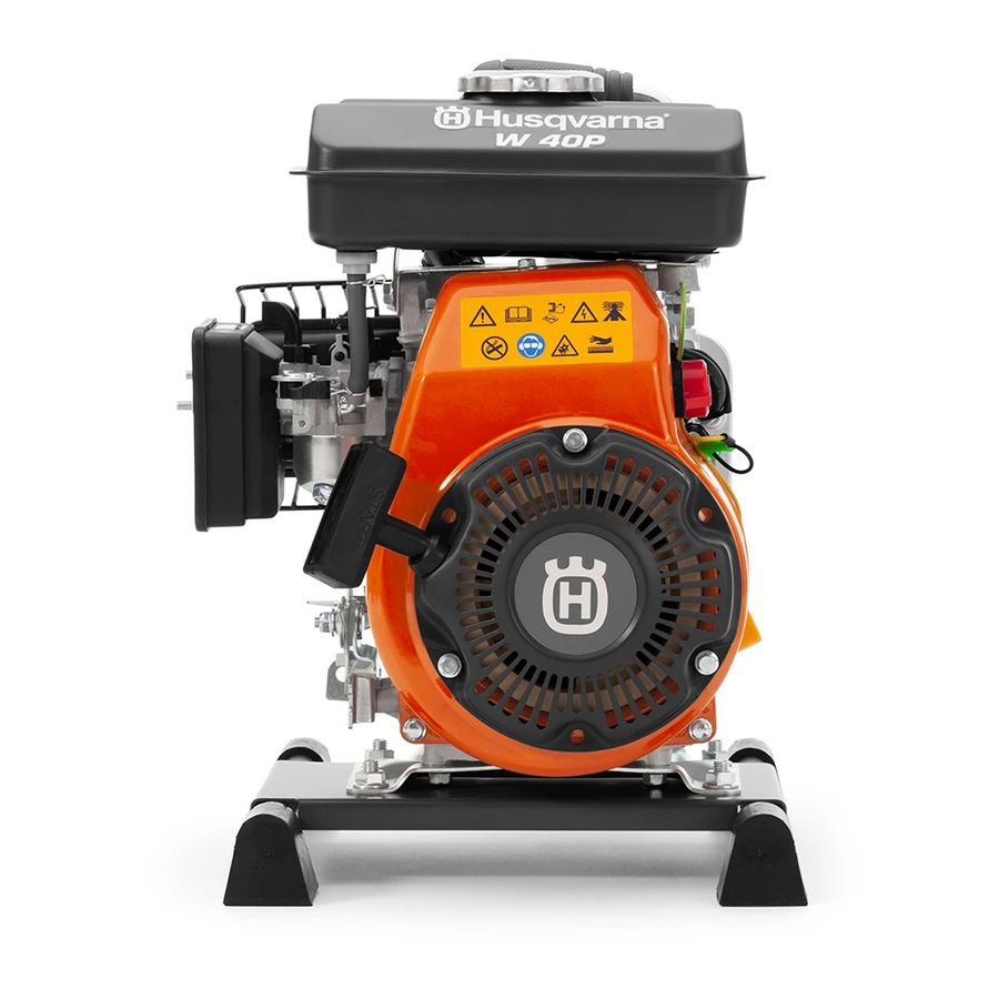
Function overview 4 Function overview 4.1 Type plate/Product serial number Figure 1 English - 11... -
Page 12: Repair Instructions
Repair instructions 5 Repair instructions 5.1 Introduction WARNING: Make sure the engine is off before you begin any repairs. This will eliminate several potential hazards: - Carbon monoxide poisoning from engine exhaust. - Burns from hot parts. - Injury from moving parts. 5.2 Product overview for repair instruction 1. - Page 13 Repair instructions 5.3 Air filter 5.3.2 To clean and examine the Air filter A dirty air filter will restrict air flow to the carburetor, reducing engine performance. 5.3.1 To disassemble the Air filter 1. Clean the air filter in warm soapy water, rinse, and allow to dry thoroughly.
- Page 14 Repair instructions 5.4 Muffler 5.4.1 To disassemble the Muffler To disassemble the muffler (1) the waterpump (2) needs to be disassemble first. See instruction 5.8.1. Figure 1 1. Remove the M6 bolts (A) and the muffler cover (B), if installed. 2.
- Page 15 Repair instructions 5.5 Fuel tank 5.5.1 To disassemble the Fuel tank Figure 1 1. Empty any remaining fuel to a suitable container. 2. Remove the M6 bolt (A) and nuts (B) to loosen the fuel tank (E). 3. Loosen the clams (D) that connects the fuel hose (C) to the fuel tank (E) Figure 2 5.5.2 To clean and examine the Fuel tank...
- Page 16 Repair instructions 5.6 Starter 3. Remove the M6 bolts (D) and the M6 bolt (E) and remove the housing (C). See Figure 2. 5.6.1 To disassemble the Starter 5.6.2 To clean and examine the Starter 1. Clean the Starter. 2. Examine the Starter for damages. Replace dam- aged parts.
- Page 17 Repair instructions 5.7 Engine oil 5.7.3 To fill the product with engine oil 5.7.1 To change the oil 1. With the engine in a level position, fill to the edge of Drain the used oil while the engine is warm. Warm oil the oil filler hole with the recommended oil.
- Page 18 Do not use a hose smaller than the pump s suction port size. Minimum hose size W 40P 1.5 inch 40 mm The suction hose (G) should be no longer than neces- sary. Pump performance is best when the pump is near the water level and the hoses are short.
- Page 19 Repair instructions Securely tighten the hose connector on the pump suc- tion port. Discharge hose installation (see Figure 3) Use a commercially available hose (J). Use the hose connector and the hose clamp provided with the pump. It is best to use a short, large-diameter hose, because that will reduce fluid friction and improve pump output.
- Page 20 Repair instructions 5.9 Spark plug 5.9.4 To examine the ignition spark 1. Remove the spark plug and clean it from soot 5.9.1 To disassemble the Spark plug deposits with the help of a steel brush. Check the 1. Remove any dirt from the sparkplug area. electrode gap.
- Page 21 Repair instructions 5.10 Carburettor 5.10.2 To clean and examine the Carburet- 5.10.1 To disassemble the Carburettor 1. Shut off the fuel valve (N). 1. Remove the screw (A) and remove the air filter 2. Remove the screw (O) and remove the carburettor cover (B) and air filter (C).
-
Page 22: Troubleshooting
Troubleshooting 6 Troubleshooting No pump output 6.1 General troubleshooting Possible problem Action Pump is placed Place the pump on a firm, level The different faults which may occur on the product are on inappropriate surface. divided into four groups. Within each group places. -
Page 23: Technical Data
Technical data 7 Technical data Inlet/outlet size (mm) Lift (m) Suction (m) Engine model 152F Max discharge capacity (M/H) Max power (HP) Fuel tank capacity (L) N.W/G.W (kg) 13/14 English - 23... - Page 24 115 99 67-26 2018-06-07...