Dialog Semiconductor DA14585 User Manual
Voice rcu hardware
manual
Hide thumbs
Also See for DA14585:
- User manual (99 pages) ,
- Quick start manual (2 pages) ,
- User manual (45 pages)
Table of Contents
Advertisement
Quick Links
Download this manual
See also:
User Manual
User Manual
DA14585 Voice RCU Hardware
Manual
UM-B-087
Abstract
This document describes the hardware design of the DA14585 Voice RCU reference design (Rev.B),
which is based on the Dialog Semiconductor DA14585 Bluetooth® low energy SoC. This reference
design includes an accelerometer/gyro sensor, digital microphone, keypad, and a trackpad which is
placed on a separate daughterboard.
Advertisement
Table of Contents

Related Manuals for Dialog Semiconductor DA14585


Summary of Contents for Dialog Semiconductor DA14585
-
Page 1: Abstract
UM-B-087 Abstract This document describes the hardware design of the DA14585 Voice RCU reference design (Rev.B), which is based on the Dialog Semiconductor DA14585 Bluetooth® low energy SoC. This reference design includes an accelerometer/gyro sensor, digital microphone, keypad, and a trackpad which is... -
Page 2: Table Of Contents
Introduction............................ 4 System Overview ........................... 5 Features ..........................5 Block Diagram ........................5 PCBA Overview ........................6 DA14585 Voice RCU Reference Design ..................9 DA14585 SoC ........................9 Pin Assignment ........................10 Power Management ......................11 Flash Memory ........................11 Crystal Oscillators ....................... -
Page 3: Figures
Figure 20: PCB view of a printed antenna ................... 19 Figure 21: Printed Antenna Radiation Pattern..................19 Figure 22: DA14585 Voice RCU Reference Design Rev. B1 - SoC, Flash Memory, Debugging Port 20 Figure 23: DA14585 Voice RCU Reference Design Rev. B1 – Peripherals, Sensors ......21 Figure 24: DA14585 Voice RCU Reference Design Rev. -
Page 4: Terms And Definitions
The Dialog Voice RCU reference design builds on its best-in-class Bluetooth low energy solution, the DA14585, to deliver an RCU with world-leading battery lifetime and a very small Bill of Materials. User Manual Revision 1.0... -
Page 5: System Overview
Printed Keypad Antenna JTAG UART BMI160 Reset On/Off Debugging Accelerometer/ Switch Header Button Gyro Figure 1: Top Level Block Diagram of the DA14585 Voice RCU Reference Design User Manual Revision 1.0 09-Jun-2017 © 2017 Dialog Semiconductor CFR0012 5 of 34... -
Page 6: Pcba Overview
UM-B-087 DA14585 Voice RCU Hardware Manual PCBA Overview ANT1 IR LED Reset Button DA14585 BMI160 Accelerometer /Gyro Trackpad sockets JTAG Power connector On/OFF Buzzer switch Keypad Battery Holder Figure 2: DA14585 Voice RCU Figure 3: DA14585 Voice RCU Reference Design (Rev B) -... -
Page 7: Figure 4: Trackpad Daughterboard (Rev B) - Top View
UM-B-087 DA14585 Voice RCU Hardware Manual Figure 4: Trackpad Daughterboard (Rev B) – Top View Figure 5: Trackpad Daughterboard (Rev B) – Bottom View User Manual Revision 1.0 09-Jun-2017 © 2017 Dialog Semiconductor CFR0012 7 of 34... -
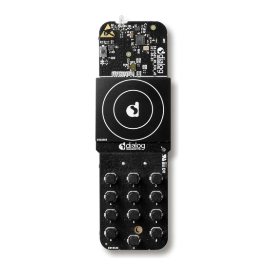
Page 8: Figure 7: Complete Da14585 Voice Rcu Reference Design (Rev B) With Track Wheel
UM-B-087 DA14585 Voice RCU Hardware Manual Figure 6: Complete DA14585 Figure 7: Complete DA14585 Voice RCU Reference Design Voice RCU Reference Design (Rev B) with Track Wheel (Rev B) with Trackpad User Manual Revision 1.0 09-Jun-2017 © 2017 Dialog Semiconductor... -
Page 9: Da14585 Voice Rcu Reference Design
DA14585 Voice RCU Hardware Manual DA14585 Voice RCU Reference Design DA14585 SoC The DA14585 integrated circuit is an optimized version of the DA14580, offering a reduced boot time and supporting up to eight connections. It has a fully integrated radio transceiver and baseband ®... -
Page 10: Pin Assignment
DA14585 Voice RCU Hardware Manual Pin Assignment Table 1 shows the pin assignment and related pin names on the QFN40 package of the DA14585. Table 1: DA14585 Voice RCU Reference Design Rev. B - Pin Assignment DA14585 QFN40 Pin Name... -
Page 11: Power Management
7 mm long. Flash Memory Figure 9: Serial NOR Flash Memory The DA14585 uses an external Serial NOR Flash memory for mirroring its contents to RAM and execute. The Flash memory type used is MX25R2035: ●... -
Page 12: Crystal Oscillators
DA14585 Voice RCU Hardware Manual Crystal Oscillators The DA14585 SoC has two Digitally Controlled Crystal Oscillators (DCXO), one at 16 MHz (XTAL16M) and a second at 32.768 kHz (XTAL32K). The 32.768 kHz oscillator has no trimming capabilities and is used as the clock for the Extended/Deep Sleep modes. The 16 MHz oscillator can be trimmed. -
Page 13: Microphone
UM-B-087 DA14585 Voice RCU Hardware Manual Microphone SPK0838HT4H-B from Knowles is a miniature, high performance, low power, top port silicon digital microphone with a single-bit PDM output. Its power consumption during sleep is only 4.6 A. Figure 10: SPK0838HT4H Microphone Schematic User Manual Revision 1.0... -
Page 14: Capacitive Touch Controller
Azoteq while the wheel pad is using the IQS263 from same vendor. These controllers have the ability to sense touch and are accessible by the DA14585 via the I2C interface. Figure 11: Capacitive Touch Controller Schematic (Trackpad) Figure 12: Capacitive Touch Controller Schematic (Wheel) User Manual Revision 1.0... -
Page 15: Accelerometer/Gyroscope Sensor
In full operation mode, with the accelerometer and gyroscope enabled, the current consumption is typically 950 A, while this is dropped down to 3 A is suspend mode. The BMI160 module is connected to the DA14585 via an SPI interface. -
Page 16: Infrared Led
UM-B-087 DA14585 Voice RCU Hardware Manual Infrared LED The DA14585 voice RCU reference design employs the WP7113F3BT IR LED from Kingbright. A Schottky diode NSVR0240V2T1G is used to ensure that no current will be reflected back to battery. The IR LED is driven by the P2_0 GPIO via a transistor switch. -
Page 17: 5.11 On/Off Switch
5.12 LEDs Figure 17: Indication LEDs Schematic The DA14585 Voice RCU reference design is equipped with a Red LED (D5) and a Green LED (D6), which are used to indicate programming and keypad/trackpad operations, respectively. The Red LED is controlled by GPIO P1_2, the Green LED by GPIO P1_3. -
Page 18: 5.13 Reset Button
DA14585 Voice RCU Hardware Manual 5.13 Reset Button Figure 18: Reset Button Schematic and Actual Illustration The DA14585 Voice RCU reference design employs a reset button (SW37) for applying a hard reset of the DA14585 SoC. 5.14 Keypad Matrix Figure 19: Keypad Matrix Schematic The DA14585 Voice RCU reference design uses a fully configurable 3 columns by 4 rows keypad matrix. -
Page 19: 5.15 Printed Antenna
The antennas used in this reference design was based on the Designing Printed Antennas for Bluetooth® Low Energy application note. Figure 21 shows the radiation pattern of the printed IFA antenna used in the DA14585 Voice RCU reference design. The antenna performance is summarized in Table... -
Page 20: Schematics
UM-B-087 DA14585 Voice RCU Hardware Manual Schematics Figure 22: DA14585 Voice RCU Reference Design Rev. B1 - SoC, Flash Memory, Debugging Port User Manual Revision 1.0 09-Jun-2017 © 2017 Dialog Semiconductor CFR0012 20 of 34... -
Page 21: Figure 23: Da14585 Voice Rcu Reference Design Rev. B1 - Peripherals, Sensors
UM-B-087 DA14585 Voice RCU Hardware Manual Figure 23: DA14585 Voice RCU Reference Design Rev. B1 – Peripherals, Sensors User Manual Revision 1.0 09-Jun-2017 © 2017 Dialog Semiconductor CFR0012 21 of 34... -
Page 22: Pcb Layout
UM-B-087 DA14585 Voice RCU Hardware Manual PCB Layout Figure 24: DA14585 Voice RCU Reference Design Rev. B - Top View User Manual Revision 1.0 09-Jun-2017 © 2017 Dialog Semiconductor CFR0012 22 of 34... -
Page 23: Figure 25: Da14585 Voice Rcu Reference Design Rev. B - Bottom View
UM-B-087 DA14585 Voice RCU Hardware Manual Figure 25: DA14585 Voice RCU Reference Design Rev. B - Bottom View This is a 2-layer FR-4 PCB with approx. 1.6 mm thickness as can be seen from the stack-up figure below: Figure 26: DA14585 Voice RCU Reference Design - PCB Stack-Up User Manual Revision 1.0... -
Page 24: Power Measurements
DA14585 Voice RCU Hardware Manual Power Measurements This chapter contains current consumption measurement results for the DA14585 Voice RCU Reference Design. These measurements were conducted using the Agilent DC power analyzer N6705B with the reference design connected to a mobile phone application. -
Page 25: Figure 29: Da14585 Voice Rcu Reference Design - Average Touch Pad Scanning Current
DA14585 Voice RCU reference design, emphasizing the scanning pulse generated by the touch pad controller. Figure 30: DA14585 Voice RCU Reference Design – Current during Touch Pad Scan Pulse Table 6: DA14585 Voice RCU Reference Design... -
Page 26: Enclosure
UM-B-087 DA14585 Voice RCU Hardware Manual Enclosure Figure 31: DA14585 Voice RCU Reference Design Enclosure – Top View Debugging port Figure 32: DA14585 Voice RCU Reference Design Enclosure – Bottom View User Manual Revision 1.0 09-Jun-2017 © 2017 Dialog Semiconductor... -
Page 27: Figure 33: Connection Of Jtag Cable With Da14585 Voice Rcu Pcb Inside Enclosure
UM-B-087 DA14585 Voice RCU Hardware Manual Figure 33: Connection of JTAG Cable with DA14585 Voice RCU PCB Inside Enclosure Figure 34: Connection of CIB Board with DA14585 Voice RCU PCB inside the Enclosure User Manual Revision 1.0 09-Jun-2017 © 2017 Dialog Semiconductor... -
Page 28: Figure 35: Da14585 Voice Rcu Reference Design Enclosure - Top Exploded View
UM-B-087 DA14585 Voice RCU Hardware Manual Figure 35: DA14585 Voice RCU Reference Design Enclosure – Top Exploded View Figure 36 : DA14585 Voice RCU Reference Design Enclosure - Side Exploded View User Manual Revision 1.0 09-Jun-2017 © 2017 Dialog Semiconductor... -
Page 29: 10 Configuration Of The Debugging Interface
UM-B-087 DA14585 Voice RCU Hardware Manual 10 Configuration of the Debugging Interface The DA14585 voice RCU reference design has a dedicated debugging port as shown in Figure 37 Two debugging ports are used on the DA14585 SoC: JTAG and UART. -
Page 30: Figure 39: Communication Interface Board (Cib)
● Connectivity of PC to the DA14585 JTAG port ● Connectivity of PC to the DA14585 UART port (full UART is possible but it must be enabled on the PC driver) ● Hardware RESET capability. Note that the RESET signal is active high. -
Page 31: Figure 40: Connection Of The Da14585 Voice Rcu Pcb To The Cib Programming Board
UM-B-087 DA14585 Voice RCU Hardware Manual Figure 40: Connection of the DA14585 Voice RCU PCB to the CIB Programming Board User Manual Revision 1.0 09-Jun-2017 © 2017 Dialog Semiconductor CFR0012 31 of 34... -
Page 32: 10.1 Debug/Programming Interface Scenarios
UM-B-087 DA14585 Voice RCU Hardware Manual 10.1 Debug/Programming Interface Scenarios The following two scenarios are targeted to help the user to successfully debug/program the DA14585 Voice RCU reference design. 10.1.1 Scenario 1: RCU Inside the Enclosure In this case the user must have the batteries installed before connecting the CIB programming/... -
Page 33: Revision History
UM-B-087 DA14585 Voice RCU Hardware Manual Revision History Revision Date Description 09-Jun-2017 Initial version. User Manual Revision 1.0 09-Jun-2017 © 2017 Dialog Semiconductor CFR0012 33 of 34... -
Page 34: Um-B
Dialog Semiconductor excludes all liability in this respect. Customer notes that nothing in this document may be construed as a license for customer to use the Dialog Semiconductor products, software and applications referred to in this document. Such license must be separately sought by customer with Dialog Semiconductor.
Need help?
Do you have a question about the DA14585 and is the answer not in the manual?
Questions and answers