Table of Contents
Advertisement
Advertisement
Table of Contents

Related Manuals for Kenwood WD-K10 Series

Summary of Contents for Kenwood WD-K10 Series
- Page 1 WD-K10 series DECT Intercom System USER MANUAL B5A-1775-00...
-
Page 2: Table Of Contents
INTRODUCTION Contents Configuring in Setup Menu Mode INTRODUCTION Setting Key Lock On/Off Contents Changing the PTT Key Setting How to Read This USER MANUAL Manual Reconnection (Transceiver Symbols Used Mode Only) Content of This User Manual Notification Tones During the Use of Transceiver Features Voice Announcement... -
Page 3: Contents
1 INTRODUCTION 1.1 Contents OTHERS Troubleshooting Specifications Contents... -
Page 4: How To Read This User Manual
Note Content of This User Manual All rights reserved by JVC KENWOOD Corporation. Unauthorized duplication or reprinting of this user manual, in whole or in part, is strictly prohibited. Other product and company names included in this user manual are trademarks and/or registered trademarks of their ®... -
Page 5: Features
1 INTRODUCTION 1.3 Features Features The use of 1.9 GHz band digital communication technology allows for crisp and clear calls to be made in confidentiality. Licenses and application procedures are not required; the device can be used immediately on the day it was set up. A flexible system can be set up, from a small-scale system using one Portable base WD-K10PBS or Base Station WD- K10BS, to a large-scale system combining several base stations. -
Page 6: Precautions
1 INTRODUCTION 1.4 Precautions Precautions As far as possible, use the transceiver and portable base at a distance away from external wireless systems. An error due to radio wave interference may occur if they are too near. Using earphones in a dry environment may cause tingling sensation in the ears. This is due to the static charges accumulated on the body and the connected device, not malfunctioning of the earphones. -
Page 7: Precautions For Proper Use
1 INTRODUCTION 1.6 Precautions for Proper Use Precautions for Proper Use Portable base/Transceiver Do not drop or knock these devices. These are precision equipment that may malfunction if subject to strong impact. Clip Microphone with Earphone, Headset Do not use a non-compatible clip microphone with earphone, headset. This may cause malfunction. When pulling off the clip microphone, earphone, or headset microphone adapter, do not pull the cable. -
Page 8: System Configuration
1 INTRODUCTION 1.7 System Configuration System Configuration System Configuration Diagram Headset Clip Microphone with Clip Microphone with Interface Cable Interface Cable KHS-37 Earphone EMC-14 Earphone EMC-13 WD-RC50 WD-RC100 Transceiver Portable Base WD-K10TR WD-K10PBS PC for System Setup Base Station WD-K10BS Charger Battery Pack AC Adapter... - Page 9 1 INTRODUCTION 1.7 System Configuration System Configuration Table Model Name Product Name Remarks WD-K10PBS Portable Base It is a transceiver for wireless communication as a base unit or sub unit of the DECT intercom system. WD-K10TR Transceiver It is a transceiver that is the sub unit of the DECT intercom system. It communicates wirelessly with the Portable Base or Base Station.
- Page 10 1 INTRODUCTION 1.7 System Configuration System Type This product is a DECT intercom system that combines and uses both base and sub units. The system may be of a portable or non-portable type, depending on the type of base unit. Note The base and sub units have already been configured for your system when you receive the transceiver.
-
Page 11: Contents
1 INTRODUCTION 1.7 System Configuration Non-Portable Type Stand-alone One Base Station WD-K10BS is operated as a base unit. Up to 10 sub units can be connected at Normal Audio Quality using the Portable Base WD-K10PBS (Transceiver Mode) or the Transceiver WD-K10TR. Up to 5 sub units can be connected at High Audio Quality (a maximum of 10 units (or 5 units at High Audio Quality) can be used for simultaneous calls). -
Page 12: Contents
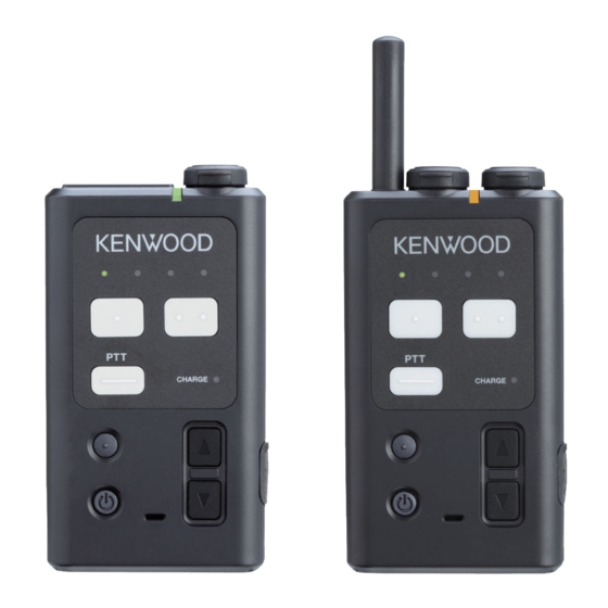
1 INTRODUCTION 1.7 System Configuration Baselink For a non-portable type system, the area can be expanded by wiring multiple (maximum 4) base stations WD-K10BS. One WD-K10BS is operated as a main base unit, and the rest (maximum 3 units) is operated as secondary base units. The main base unit WD-K10BS can be connected to external devices. - Page 13 1 INTRODUCTION 1.8 Part Names and Functions (Device Connection Method) Part Names and Functions (Device Connection Method) Note For details on the connection method of the connecting jack of various devices, please consult the authorized dealer or installer. Portable Base WD-K10PBS/Transceiver WD-K10TR WD-K10PBS WD-K10TR Contents...
-
Page 14: Contents
1 INTRODUCTION 1.8 Part Names and Functions (Device Connection Method) Antenna PMR Link jack For performing PMR Link. Single external wireless trigger jack. Status LED Indicates the status of the transceiver. Status Indication Base Station Mode Transceiver Mode Normal Mode/ Blinking green (slow) ―... -
Page 15: Contents
1 INTRODUCTION 1.8 Part Names and Functions (Device Connection Method) Power key Press and hold to turn the power on/off. Press to check the remaining capacity in the battery. The battery charge LED blinks. Microphone When making a call with the transceiver without using the clip microphone, speak into this microphone. This key is disabled when a clip microphone or headset microphone adapter which is sold separately is connected. -
Page 16: Base Station Wd-K10Bs
1 INTRODUCTION 1.8 Part Names and Functions (Device Connection Method) Base Station WD-K10BS FRONT REAR Status LED Indicates the status of the base station with the LED color. Antenna For registering sub units to the base station through wireless communication. [Registration] key Cover (DC plug area) Remove the cover when connecting the AC adapter to the DC IN jack or when the data setting connector and baselink... -
Page 17: Contents
1 INTRODUCTION 1.8 Part Names and Functions (Device Connection Method) Underneath the Cover (DC Plug Area) There is a packing for the DC plug area underneath the cover (DC plug area). Remove the packing to use the DC IN jack, Data setting connector and Baselink/ External Control terminal block. - Page 18 1 INTRODUCTION 1.8 Part Names and Functions (Device Connection Method) Baselink/ External Control terminal For operating the base station as the Baselink system or controlling an external device. When operating in Baselink system, change the settings with the Mode select switch ( on page 18), and connect the baselink control terminal blocks of the base units with a wiring cable.
-
Page 19: Contents
1 INTRODUCTION 1.8 Part Names and Functions (Device Connection Method) Underneath the Packing (Setting/ Adjust Area) There is an Ext Audio input/output jack, a volume adjust knob and a Mode select switch underneath the packing. Ext Audio input/output jacks (2 lines) Group calls can be output externally by connecting this unit to an external audio equipment. -
Page 20: Contents
1 INTRODUCTION 1.8 Part Names and Functions (Device Connection Method) Status LED Indication Operation Mode Indication Stand-alone Baselink Baselink Base Unit Main Base Unit Secondary Base Unit Blinking green (slow) ― ― Normal Mode Wireless Sub Unit Registration Wireless Sub Unit Registration Green Mode Mode... -
Page 21: Charger Ksc-48Cr
1 INTRODUCTION 1.8 Part Names and Functions (Device Connection Method) Charger KSC-48CR The charger KSC-48CR can be combined and used with the separately available AC adapter KSC-44SL or KSC-44ML. Transceiver charging slot Charging port for inserting the transceiver to be charged. Charging terminal Bottom Connecting bracket... -
Page 22: Clip Microphone With Earphone Emc-13
1 INTRODUCTION 1.8 Part Names and Functions (Device Connection Method) Clip Microphone with Earphone EMC-13 Microphone clip Use this to attach to the collar of your clothes. [PTT] key Press this key for business contact as an intercom. Transceiver connection plug For connecting to an appropriate transceiver. -
Page 23: Clip Microphone With Earphone Emc-14
1 INTRODUCTION 1.8 Part Names and Functions (Device Connection Method) Clip Microphone with Earphone EMC-14 Microphone clip Use this to attach to the collar of your clothes. [PTT] key Press this key for business contact as an intercom. Transceiver connection plug For connecting to an appropriate transceiver. -
Page 24: Headset Khs-37
1 INTRODUCTION 1.8 Part Names and Functions (Device Connection Method) Headset KHS-37 Microphone clip with [PTT] key Press this key for business contact as an intercom. Transceiver connection plug For connecting to an appropriate transceiver. Microphone To speak, adjust the boom microphone such that it is about 1 cm away from your mouth. The boom microphone can be moved up and down. -
Page 25: Interface Cable Wd-Rc50
It is used to connect to the Portable base WD-K10PBS. PMR Link jack Connect to the 2-pin connector of the two-way radios of the KENWOOD in an external wireless system. After connecting to the transceiver, turn the cap and secure. -
Page 26: Contents
It is used to connect to the Portable base WD-K10PBS. PMR Link jack Connect to the universal connector of the two-way radios of the KENWOOD in an external wireless system. After connecting to the transceiver, turn the cap and secure. -
Page 27: Preparing The Device
PREPARATION Preparing the Device Replacing the Battery Pack This transceiver comes with the battery pack already installed in it. To replace the battery pack, follow the steps below to remove and install the battery pack. Remove the screws (x6) on the rear of the transceiver and remove the rear cover. Take out the battery pack and remove the battery connector. - Page 28 2 PREPARATION 2.1 Preparing the Device Arrange the battery cable as shown in the illustration and push in the battery. Push in firmly until the catches are sitting on the battery pack. Catch Catch Catch Attach the rear cover to the transceiver unit and tighten the screws (x6). After installing the battery pack, attach the rear cover and secure it by tightening the screws.
-
Page 29: Charging The Battery Pack
2 PREPARATION 2.1 Preparing the Device Charging the Battery Pack Be sure to charge the transceiver using the charger KSC-48CR before using. Remove the bracket underneath the charger and insert the DC plug of the AC adapter into the DC IN jack of the charger. -
Page 30: Attaching The Belt Clip
The clip microphone or headset microphone adapter is also disabled. For information on supported accessories of the clip microphone or headset microphone adapter, please refer to the DECT intercom system WD-K10 series website. http://manual.kenwood.com/en_contents/search/keyword Contents... -
Page 31: Connecting The Transceiver Connection Cable
Connect the transceiver connection cable WD-RC100 or WD-RC50 to allow communication between the DECT intercom system WD-K10 series and external wireless systems (KENWOOD brand). Compatible models: Two-way radios of the KENWOOD brand that can be connected to the transceiver connection cable WD-RC100 or WD- RC50 are as follows: WD-RC100: NX-200G, NX-300G, NX-5200, NX-5300... - Page 32 2 PREPARATION 2.1 Preparing the Device Connecting to an External Wireless System Transceiver Insert the guide of the transceiver connection cable into the groove of the transceiver, and secure tightly with screws. The screws can be tightened by hand but in order to ensure water resistance, use a coin screwdriver to tighten or remove. Precautions When using two-way radio, do not use or place it on the charger.
- Page 33 2 PREPARATION 2.2 Turning On/Off the Device Power Turning On/Off the Device Power Turning On/Off the Power of WD-K10BS Turning on the Power Plug the AC adapter of WD-K10BS into the AC outlet to turn on. To AC OUTLET Turning off the Power Unplug the AC adapter of WD-K10BS from the AC outlet to turn off the power.
-
Page 34: Turning On/Off The Power Of Wd K10Pbs / Wd-K10Tr
2 PREPARATION 2.2 Turning On/Off the Device Power Turning On/Off the Power of WD-K10PBS / WD-K10TR Turning on the Power Hold down the [Power] key. Release after the Status LED (red), Group LEDs, and Battery Charge LED light up and then light off. Base Station Mode When the unit is linked to the system, the Status LED blinks in orange. -
Page 35: Registering The Device
2 PREPARATION 2.3 Registering the Device Registering the Device Registering Sub Unit to Base Unit This system is used when the transceiver to be used as a sub unit is registered to the Portable base WD-K10PBS or Base station WD-K10BS that is to be used as the base unit. Register side by side Sub Unit Base Unit... - Page 36 2 PREPARATION 2.3 Registering the Device Registering Sub Unit to WD-K10PBS (Base Station Mode) Note For details on how to switch WD-K10PBS to Transceiver Mode, refer to Starting WD-K10PBS in Transceiver Mode on page Turn off the base unit and sub unit if they have been turned on. Press and hold the [Power] key until the Status LED goes off to turn off the power.
- Page 37 2 PREPARATION 2.3 Registering the Device Restart the sub unit. When registration of sub unit is successful, restart the sub unit. After the registration is complete, turn on the power of the base unit and restart as well. Note To exit registration mode, press and hold the [PF 2] key. If registration fails repeatedly, the maximum number of registrations may have been exceeded.
- Page 38 2 PREPARATION 2.3 Registering the Device Start the sub unit in registration mode. While pressing the [All Call] key of the sub unit, press and hold the [Registration] key until the Status LED lights up in green and all the Group LEDs are blinking. The sub unit enters into registration mode.
- Page 39 2 PREPARATION 2.3 Registering the Device Starting WD-K10PBS in Transceiver Mode WD-K10PBS can be used as a base unit or sub unit. To use as a sub unit, perform the following operations and start in Transceiver Mode. Precautions The mode in WD-K10PBS has been configured to your system in advance. Unless it is necessary, do not change the startup mode.
- Page 40 2 PREPARATION 2.4 Setting Various Functions Setting Various Functions Adjusting the Receiver Volume Level Use the [J]/[K] key to adjust to an appropriate volume level. Use the [J] key to increase the current volume level by 1. Use the [K] key to lower the current volume level by 1. Note Pressing and holding the [J]/[K] key does not adjust the volume continuously.
- Page 41 2 PREPARATION 2.4 Setting Various Functions Checking Battery Remaining Capacity You can check the current battery remaining capacity. Press the [Power] key. A voice announcement according to the battery remaining capacity is being played. The battery charge LED will display the remaining capacity for 4 seconds. Group LED Status LED [Power] key...
-
Page 42: Configuring In Setup Menu Mode
2 PREPARATION 2.4 Setting Various Functions Configuring in Setup Menu Mode Start the transceiver in Setup menu mode to configure various functions. If the unit is turned on, turn off the power by pressing and holding the [Power] key until the Status LED goes off. - Page 43 2 PREPARATION 2.4 Setting Various Functions Press the [PTT] key and confirm a setup item. Press the [J], [K] key and select a setting. A voice announcement will be played for the setting details every time a setting is switched. To return to selecting a setup item, press the [PF 1] key.
-
Page 44: Setting Key Lock On/Off
2 PREPARATION 2.4 Setting Various Functions Setting Key Lock On/Off Lock the function keys and All Call key of the transceiver to prevent the keys from being operated. Precautions This function cannot be executed by default. For details on the settings, please consult the authorized dealer or installer. Setting Key Lock On Key operation during key lock is disabled. -
Page 45: Changing The Ptt Key Setting
2 PREPARATION 2.4 Setting Various Functions Changing the PTT Key Setting “PTT”, “PTT-Lock”, or “VOX” can be selected for the Talk Setting. Precautions The [Switch Talk Function] key is not assigned by default. Assign the function to any function keys. To configure the setting, consult the authorized dealer or installer. -
Page 46: Manual Reconnection (Transceiver Mode Only)
2 PREPARATION 2.4 Setting Various Functions Manual Reconnection (Transceiver Mode Only) Reconnect regardless of the radio wave status. Precautions The [Manual Reconnection] key is not assigned by default. Assign the function to any function keys. For details on the settings, please consult the authorized dealer or installer. Press the [Manual Reconnection] key. -
Page 47: Transceiver
2 PREPARATION 2.4 Setting Various Functions Notification Tones During the Use of Transceiver Depending on the selected mode and status, you can hear the notification tones of the transceiver from earphones. The following table shows the name and content of various notification tones. Name Status Alert tone... -
Page 48: Voice Announcement
2 PREPARATION 2.4 Setting Various Functions Voice Announcement Voice announcements for the operation of the Portable base WD-K10PBS and Transceiver WD-K10TR will be played. Voice Announcement Guide Voice Announcement Description Content Audio Connected Group★ Group (Number) The connected group number when a sub unit is connected to the base unit, or when the [Group Select] key is pressed and a group has been switched. -
Page 49: Making A Call
MAKING A CALL Operation Mode The following operation modes are available in a call. Name of Operation Mode Operation Status Group Call ( on page Operation mode as an intercom. All members in the same group can hear the conversation. Group Select ( on page All Call (... -
Page 50: Making Calls (Group Call Mode)
3 MAKING A CALL 3.2 Making Calls (Group Call Mode) Making Calls (Group Call Mode) This function allows you to talk to all members of the group that you belong to. Note Turn on the power of the transceiver to enter Group Call Mode. To change the group, consult the authorized dealer or installer. -
Page 51: When Out Of Range
3 MAKING A CALL 3.2 Making Calls (Group Call Mode) When Out of Range When a sub unit has moved out of range of the base unit connection area, the Status LED lights up in red. An Out of Range notification tone will emit when the [PTT] key is pressed. -
Page 52: Changing Groups
3 MAKING A CALL 3.3 Changing Groups Changing Groups This function allows you to call a group that has been switched. Precautions The group that has been pre-configured in the system will be switched. For details on group settings, please consult the authorized dealer or installer. -
Page 53: Calling All Groups (All Call Mode)
3 MAKING A CALL 3.4 Calling All Groups (All Call Mode) Calling All Groups (All Call Mode) You can make a call to everyone in all the groups that are using transceivers. Press and hold the [All Call] key. The All Call notification tone will emit from the transceivers of all group members and all groups can receive and send calls. -
Page 54: Using External Devices
3 MAKING A CALL 3.5 Using External Devices Using External Devices This function allows the unit to control external devices such as activating external audio source. Precautions External devices that have been pre-configured in the system will be controlled. For details on the device settings, please consult the authorized dealer or installer. -
Page 55: Performing Pmr Link
Overview of PMR Link The following models of two-way radios can be connected to external systems using PMR Link. Target transceivers: KENWOOD two-way radios Models using WD-RC100: NX-200G, NX-300G, NX-5200, NX-5300 Models using WD-RC50: NX-220, NX-320, TK-2000, TK-3000, TK-2302, TK-3302, TK-3401D, TK-3501 Contents of mixed calls within the sending area can be heard at terminals in the receiving area through two-way radios. -
Page 56: Activating The Pmr Link Function
3 MAKING A CALL 3.6 Performing PMR Link Activating the PMR Link Function The following activation methods are available for performing PMR Link. Performing PMR Link by Pressing the [PMR Link] Key on page 56 Activate and deactivate the PMR Link function using the [PMR Link] key and talk by pressing the [PTT] key. Performing PMR Link by Pressing the [PTT] Key on page 57 Link the activation and deactivation of the PMR Link function to the operation of the [PTT] key to perform PMR Link. -
Page 57: Performing Pmr Link By Pressing The Pmr Link] Key
3 MAKING A CALL 3.6 Performing PMR Link Performing PMR Link by Pressing the [PMR Link] Key By assigning the PMR Link function to any function key as a [PMR Link] key, you can activate the PMR Link function by pressing the key. -
Page 58: Performing Pmr Link By Pressing The Ptt] Key
3 MAKING A CALL 3.6 Performing PMR Link Performing PMR Link by Pressing the [PTT] Key If “Function Link Start” is set to [Enable Link with], the operation is the same as “Broadcasting by Pressing the [Broadcast] Key on page 61”. -
Page 59: Performing Pmr Link By Pressing The Pmr Link (Ptt Link)] Key
3 MAKING A CALL 3.6 Performing PMR Link Performing PMR Link by Pressing the [PMR Link (PTT Link)] Key By assigning the PMR Link (PTT Link) function to any function key, you can activate the PMR Link function and start the PMR Link by a single [PMR Link (PTT Link)] key operation. -
Page 60: Making Calls In High Audio Quality
3 MAKING A CALL 3.7 Making Calls in High Audio Quality Making Calls in High Audio Quality The audio quality of calls between devices can be configured in this system. When “High Quality” is selected for “Audio Quality” in System setup, high-frequency audio can also be transmitted by bundling multiple communication for “Normal”... -
Page 61: Broadcasting
3 MAKING A CALL 3.8 Broadcasting Broadcasting This function uses external devices to broadcast directly to a facility or floor. Activating the Broadcast Function The following activation methods are available for performing broadcast. Broadcasting by Pressing the [Broadcast] Key on page 61 Activate and deactivate the Broadcast function using the [Broadcast] key and talk by pressing the [PTT] key. -
Page 62: Broadcasting By Pressing The Broadcast] Key
3 MAKING A CALL 3.8 Broadcasting Broadcasting by Pressing the [Broadcast] Key By assigning the Broadcast function to any function key as a [Broadcast] key, you can activate the Broadcast function by pressing the key. Press the [Broadcast] key. The Broadcast function will activate and a mode change tone will emit from the activated transceiver. Broadcast Speak into the microphone while pressing the [PTT]... -
Page 63: Broadcasting By Pressing The [Ptt] Key
3 MAKING A CALL 3.8 Broadcasting Broadcasting by Pressing the [PTT] Key By setting “Function Link with” to “Broadcast” and “Function Link Start” to “Enable Link with” in “Talk Setting”, you can activate the Broadcast function and start the broadcast by a single [PTT] key operation. Press the [PTT] key on the clip microphone or transceiver. -
Page 64: Broadcasting By Pressing The Broadcast(Ptt Link)] Key
3 MAKING A CALL 3.8 Broadcasting Broadcasting by Pressing the [Broadcast(PTT Link)] Key By assigning the Broadcast(PTT Link) function to any function key, you can activate the Broadcast function and start the broadcast by a single [Broadcast(PTT Link)] key operation. Similarly, you can also end the broadcast by a single operation. Press the [Broadcast(PTT Link)] key. -
Page 65: Using Listening Mode
USING LISTENING MODE Listening Mode “Listening Mode” is available in this system where multiple sub units (transceivers) are configured to only receive calls. The usage environment and sub unit operation may be limited when using the sub unit in the Listening Mode. However, more sub units can be operated with few base units (base stations). -
Page 66: Limitations Of Listening Mode
4 USING LISTENING MODE 4.1 Listening Mode Limitations of Listening Mode Target models: Portable base WD-K10PBS Transceiver WD-K10TR Base station WD-K10BS Usage environment: When units are out of range from the connection area, the Status LED lights up in red and calls cannot be heard (an Out of Range notification tone will emit depending on the setting). - Page 67 4 USING LISTENING MODE 4.2 Calling from Sub Units in Listening Mode (Listening Talk) Calling from Sub Units in Listening Mode (Listening Talk) When there is an empty channel in the base station, sub units in Listening Mode can change into “Listening Talk” mode to send calls temporarily.
-
Page 68: Changing Groups
4 USING LISTENING MODE 4.4 Changing Groups Changing Groups Only groups in which voice channels 1 to 4 have been configured in Groups A to D can be switched. Precautions The group that has been pre-configured in the system will be switched. For details on group settings, please consult the authorized dealer or installer. -
Page 69: Switching To Group Call Mode
4 USING LISTENING MODE 4.5 Switching to Group Call Mode Switching to Group Call Mode Sub units in the Listening Mode will switch to the Group Call Mode. Precautions The mode in the sub units has been configured to your system in advance. Unless it is necessary, do not change the startup mode. -
Page 70: Others
OTHERS Troubleshooting Check that the problem is genuine before requesting for repairs. Reference Problem Cause Solution Page The unit is prone to The surrounding environment and Adjust the “Communication Disconnect Zone entering service non- operation status affect the field Selection Level” and “Communication coverage area (out of intensity of signals emitted from the Disconnect Time”. - Page 71 5 OTHERS 5.1 Troubleshooting Reference Problem Cause Solution Page The sub unit cannot You have exceeded the number of The number of sub units connected to a base on page 9 connect even when it is connected units to a base station. station is up to 10 in Normal Audio Quality or 5 near the base station.
-
Page 72: Specifications
5 OTHERS 5.2 Specifications Specifications Specifications and external appearance of the product are subject to change for improvement without prior notice. Portable base WD-K10PBS Transmission/Receiving frequency 1.9 GHz band Transmission power 10 mW and below (average) Type of radio wave F1D, F1E Receiving sensitivity -90 dBm@BER1x10... - Page 73 5 OTHERS 5.2 Specifications Base Station WD-K10BS Transmission/Receiving frequency 1.9 GHz band Transmission power 10 mW and below (average power per channel) Type of radio wave F1D, F1E Receiving sensitivity -90 dBm@BER1x10 and below Contact terminals Audio input x 2 [Stereo standard jack]: -10 dBs (balance or unbalanced) Audio output x 2 [Stereo standard jack]: -10 dBs (balance), -16 dBs (unbalanced) Link terminal x 2 [Terminal block bipolar] (Uplink/Downlink)
- Page 74 5 OTHERS 5.2 Specifications Clip Microphone with Earphone EMC-14 Microphone unit Element type Electret condenser Sensitivity –42 dB Impedance 1.5 kΩ Earphone unit Element type Dynamic Output level 95 dB Nominal input power 50 mW Impedance 54 Ω Headset KHS-37 Microphone unit Element type Electret condenser...
- Page 75 5 OTHERS 5.2 Specifications Battery Pack WD-UB100 External dimensions 35 mm (width) x 54.6 mm (height) x 7.6 mm (thickness) Mass 30 g Nominal output voltage 3.7 V Nominal current capacity 1,430 mAh Compatible models WD-K10TR Battery Pack WD-UB110 External dimensions 35 mm (width) x 54.6 mm (height) x 10.8 mm (thickness) Mass 39 g...
- Page 76 © 2016...