Table of Contents
Advertisement
Advertisement
Table of Contents

Related Manuals for ShinewayTech OFS–95

Summary of Contents for ShinewayTech OFS–95
- Page 1 USER MANUAL Optical Fiber Fusion Splicer O F S – 95 PLEASE READ THIS INSTRUCTION MANUAL CAREFULLY BEFORE OPERATING THE EQUIPMENT. ADHERE TO ALL SAFETY INSTRUCTIONS AND WARNINGS CONTAINED IN THIS MANUAL. KEEP THIS MANUAL IN A SAFE PLACE. SHINEWAY TECHNOLOGIES, INC...
- Page 2 Report any damage to the shipping agent or the representative of Shineway Technologies, Inc. immediately. Retain the original packing materials in case reshipment becomes necessary. If necessary, please contact us via email: support@shinewaytech.com.
- Page 3 The splicer has been designed for splicing Silica-based optical fibers for telecommunications. Do not attempt to use this machine for other applications. ShinewayTech Inc. gives much consideration and regard to personal injury. Misuse of the machine may result in electric shock, fire and/or serious personal injury.
- Page 4 Warning and Caution ISO9001 Certification The product exactly conforms to ISO9001 International Quality System Standard through improving process control by ShinewayTech . It is one part of our objective which is continually increasing customers’ satisfaction.
- Page 5 Warning and Caution Safety Instructions During each stage of operation of this instrument, please always observe the following safety instructions. Not taking any safety precautions or following the instructions will violate the safety standards of design, manufacturing and application of these instruments. In no case will Shineway Technologies bear the responsibilities for consequences incurred by violation of the following instructions.
- Page 6 Warning and Caution Safety Terms Used in This Manual The WARNING sign denotes a hazard. It calls attention to a procedure, practice, or the like, which, if not correctly performed or adhered to, could result in personnel injury. Do not proceed beyond a WARNING sign until the indicated conditions are fully understood and met.
- Page 7 Warning and Caution (outlet) immediately if user observes the following or if the splicer receives the following faults: Fumes, bad smell, noise, or over-heat occurs. Liquid or foreign matter falls into cabinet. Splicer is damaged or dropped. If this occurs, ask our service center for repair. Leaving the splicer in a damaged state may cause equipment failure, electric shock or fire and may result in personal injury, death or fire.
- Page 8 Warning and Caution Safety glasses should always be worn during fiber preparation and splicing operation. Fiber fragments can be extremely dangerous if it comes into contact with the eye, skin, or is ingested. Use only proper power source. Check the AC power source before use: Proper AC power source is AC100-240V, 50-60Hz.
- Page 9 Warning and Caution electrical current may cause personal injury due to fumes, electric shock and equipment damage. Do not touch the splicer, AC power cord and AC plugs with wet hands. This may result in electric shock. Do not operate splicer near hot objects, in hot temperature environments, in dusty/humid atmospheres or when water-condensation is present on the splicer.
- Page 10 Warning and Caution result in skin burn. Do not place the splicer in an unstable or unbalanced position. The splicer may shift or lose balance, causing the unit to fall. Possible personal injury or equipment damage may result. The splicer is precision adjusted and aligned. Do not allow the unit to receive a strong shock or impact.
-
Page 11: Table Of Contents
Table of Contents Table of Contents Description of Products ....................... 11 Components of Splicer ....................11 ➢ Our Splicer ........................11 ➢ Options .................... 错误!未定义书签。 Other Necessary Items for Splicing Operation ......错误!未定义书签。 Description and Function of Splicer ................12 ➢... - Page 12 Table of Contents ➢ Fiber holder System ..................... 23 Loading Fiber to Splicer ..................... 25 ➢ Sheath Clamp ....................... 25 Splicing Procedure ....................... 26 ➢ Splice loss increase: Cause and remedy ..............28 Removing spliced fiber ....................30 Heating protection sleeve .................... 30 Maintenance of Splicing Quality ..................
- Page 13 Introduction Introduction ShinewayTech OFS-95 Optical Fiber Fusion Splicer is for fiber fusion with low splice loss and ensures splice long-time stabilization. Splice loss depends on certain conditions like fiber preparation, splicing parameters, fiber condition, variation after splicing and etc.
- Page 14 To operate by the bad environment, the splicer has improved the performance. Dropping Water-Proof Dust ShinewayTech does not guarantee that the splicer will not be damaged under these conditions. ➢ Unique function a) Operating display can be changed The OFS-95 can be operated with monitor in front or at back. The fiber/display image on the monitor can be changed.
- Page 15 Introduction d) Upgrade the software OFS-95S’s software can be upgraded via internet by using “Software Download Tool” software. Refer to the instruction manual of “Software Download Tool. ⚫ The splicer is equipped with a LCD monitor, manufactured in a high quality-controlled factory environment.
-
Page 16: Description Of Products
Description of Products Description of Products 1. Components of Splicer ➢ Our Splicer... -
Page 17: Description And Function Of Splicer
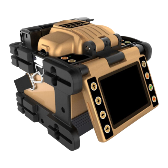
Description of Products 2. Description and Function of Splicer ➢ Front Side of OFS-95 Wind Protector Power Unit Dock ➢ Back Side of OFS-95 Output USB port Input... -
Page 18: Top Side Of Ofs-95
Description of Products ➢ Top Side of OFS-95... -
Page 19: Keypad Of Ofs-95
Description of Products ➢ Keypad of OFS-95 Left keypad Right keypad Screen keypad... -
Page 20: Point Of The Splice Procedure
Description of Products Main menu Heat Power Left Return Right Down Enter Cancel Splice Switch screen Point of the Splice Procedure 1. To Get a Stable Low Splice Loss ➢ Daily Cleaning Before Splicing Operation a) Clean the V-grooves. HINT: Sometimes, to clean the V-grooves, may need useing a stripped fiber to clean dust. b) Clean the wind protector Clamp Chips. -
Page 21: Select / Use The Suitable Splice Mode
Basic Operation c) Clean Objective Lens every week, or when it’s dirty. NOTE: Do not touch or hit electrode tips (in this case electrodes do not remove from the splicer). ➢ Select / Use the Suitable Splice Mode How to select the “Splice Mode” a) When splicing only standard SM fibers (ITU-T G.652), “SM AUTO”... - Page 22 Basic Operation b) Use only 99% or better purity alcohol. c) Do not allow the cleaved fiber ends to touch anything or become contaminated. d) Place the fiber end face between V-groove edge and Electrode center. V-groove Electrode center edge e) Place fiber in the bottom of V-groove for successful splicing.
-
Page 23: Heating
Basic Operation f) Make sure if the cleave length is correct. Fiber coating edge may hit the V-groove in case with shorter cleave length, and then the fibers may not be stuffed each other during arc discharge and result in worse splice loss. The cleave length is too short g) Do not put tension to the fibers, or the fibers may not be stuffed each other during arc discharge and result in worse splice loss. -
Page 24: Power Supply
Basic Operation a) Select the heater mode most suitable for the protection sleeve to be used. Each tube-heating mode is optimized for a type of protection sleeve. Other manufacture’s fiber protection sleeve may not shrink completely. At that time extend the heating time. b) Centering protection sleeve in tube heater 2. -
Page 25: Battery Operation
Basic Operation Turn off the splicer. Push the release button, located on the side of the splicer body, and remove the power supply out of the splice body. ➢ Battery operation Check and make sure the remaining battery capacity is 20% or greater before operation otherwise few splices can be made. -
Page 26: Turning Splicer "On
Basic Operation service agent for further instruction. 2. Turning Splicer "ON" Press [ ] and hold it until the green LED on the keypad is "ON". The “READY” screen is displayed after all the motors reset to their initial positions. The power source type is automatically identified. If the battery is used, the remaining battery capacity is displayed. -
Page 27: Fiber Preparation
Basic Operation 3. Fiber Preparation A. Placing Protection Sleeve over Fiber Clean optical fiber with alcohol-impregnated gauze or lint-free tissue approximately 100mm from the tip. Place the protection sleeve over the fiber. ⚫ Clean optical fiber with alcohol-impregnated gauze or lint-free tissue. Dust particulates can enter inside the protection sleeve and might result in a future fiber break or attenuation increase. -
Page 28: Stripping And Cleaning Fiber
Basic Operation ⚫ When protection sleeve core tube is longer than the length of outer sheath, the excess part should be cut off to avoid micro bend after heating. B. Stripping and Cleaning Fiber ➢ Sheath Clamp Strip fiber's outer coat 30 to 40 mm from its tip with a stripping tool. Clean the fiber with alcohol (Purity ≥99%) impregnated gauze or lint-free tissue thoroughly. - Page 29 Basic Operation fixture slot. Close the large plate. Push the slider to another side for cutting the fiber off; c) Open the large plate and take fiber holder out. ⚫ Do not let the fiber end-face touch anything. ⚫ Do not put fingers in the driving area of the slide button as personal injury may result.
-
Page 30: Loading Fiber To Splicer
Basic Operation 4. Loading Fiber to Splicer ➢ Sheath Clamp a) Open wind protector and sheath clamps. b) Place prepared fiber onto v-groove so that the fiber tip is located between the v-groove edge and tip of electrode. c) Hold fiber with fingers and close sheath clamp so that the fiber does not move. -
Page 31: Splicing Procedure
Basic Operation ⚫ Keep the prepared fiber out off other stuff, in case of breaking the end face of fiber. ⚫ After this step, the preparation steps are done. Close the windshield at last. Bare fiber V-groo Wrong Correct 5. Splicing Procedure To assure a good splice, the optical fiber is observed with the image processing system equipped in the OFS-95. - Page 32 Basic Operation b) After fiber inspection, the fibers are aligned core-to-core or cladding-to-cladding. Cladding axis offset and core axis offset measurements can be displayed. c) After completion of fiber alignment, arc discharge is performed to splice the fibers. d) Estimated splice loss is displayed upon completion of splicing. Splice loss is affected by certain factors stated in Page 27.
-
Page 33: Splice Loss Increase: Cause And Remedy
Basic Operation considered a normal splice, and does not affect splice loss. ⚫ To change threshold for estimated splice loss or cleave angle, see [Splice Mode] for details. ⚫ Splice loss may be improved in some cases by additional arc discharges. Press button for an additional arc discharge (re-arc). - Page 34 Basic Operation Prefuse power too low or Increase [Prefuse Power] prefuse time too short. and/or [Prefuse Time]. MFD Mismatch Increase [Arc Power] Arc power too low and/or [Arc Time]. Bad fiber end-face quality Check the cleaver Combustion Clean fiber thoroughly or Dust still present after cleaning fiber or cleaning Increase [Cleaning Arc...
-
Page 35: Removing Spliced Fiber
Basic Operation [Overlap]. Adjust [Prefuse Power], Line Some arc parameters not [Prefuse Time] or adequate [Overlap]. ⚫ A vertical line sometimes appears at the splice point when MM fibers or dissimilar fibers (different diameters) are spliced. This does not affect splice quality, such as splice loss or tensile strength. -
Page 36: Maintenance Of Splicing Quality
Basic Operation process. ⚫ Make sure the splice point is located at the center of the protection sleeve. ⚫ Make sure the strength member in the protection sleeve is placed downwards. c) Then red HEAT LED turns on. The buzzer beeps and the HEAT LED turn off when tube heating is completed. -
Page 37: Cleaning And Checking Before Splicing
Menu Operation 1. Cleaning and Checking before Splicing Critical cleaning points and maintenance checks are described below. A. Cleaning V-grooves If contaminants are present in the V-grooves, proper clamping may not occur, resulting in higher splice loss. The V-grooves should be frequently inspected and periodically cleaned during normal operation. -
Page 38: Periodical Checking And Cleaning
Menu Operation B. Cleaning Fiber Clamp Chips If contaminants are present on the clamp chips, proper clamping may not occur, resulting in poor quality splices. The fiber clamp chips should be frequently inspected and periodically cleaned during normal operation. To clean the clamp chips do the following: a) Open the wind protector. - Page 39 Menu Operation cotton swab. Using the cotton swab, start at the center of the lens and move the swab in a circular motion until you spiral out to the edge of the lens surface. c) The lens surface should be clean and free of streaks or smudges. d) Turn on the power and make sure no smudges or streaks are visible on the monitor screen.
-
Page 40: Menu Operation
Menu Operation cleaving quality. Follow the steps above until the height of stud is perfect (to see the trouble removal for details). D. Replace the blade When the blade circulation is used, and you cannot improve the cleaving quality by changing the angle of blade and adjusting the height of stud, the blade needs to be replaced. -
Page 41: Splice Mode Menu
Menu Operation 1. Splice Mode Menu A. Splice Mode The optimum splice setting for a specific fiber combination consists of the below listed splicing parameters. In other words, the optimum splicing parameters depend on the fiber combinations, and are different from fiber to fiber. ⚫... -
Page 42: Database
Menu Operation ⚫ For those who prefer the lowest possible splice loss to any other considerations. Use “AT1(SM)” and optimize splicing condition for your specific fiber combination. ⚫ For those who prefer the manual splicing to type of optical fiber has already been identified, use “SM”, “DS”, “MM1”... - Page 43 Menu Operation at wavelength of 1550 nm. Automatic arc calibration works in this splice mode. For splicing Non-zero dispersion-shifted fiber (ITU-T G655). The MFD is 9 to 10 um at wavelength AUTO NZ of 1550 nm. Automatic arc calibration works in this splice mode.
- Page 44 Menu Operation prefuse time, arc power, arc time, align, proof test, and so on. The manual splicing operaiton is provided. Automatic arc calibration doesn’t work in this splice mode. For splicing Non-zero dispersion-shifted fiber (ITU-T G655). The MFD is 9 to 10 um at wavelength of 1550 nm.
- Page 45 Menu Operation For splicing standard Single-mode fiber (ITU-T G652). The MFD is 9 to 10 um at wavelength of 1310 nm. SM FAST It is the fastest splice mode. 9 Second splicing process without considering limits. There are many types of splice modes, 12~60 BLANK (other modes) other than the ones stated above, can...
- Page 46 Menu Operation Select an appropriate splice mode for type of fiber to be spliced, press button to select splice mode, click button to confirm. “1 AUTO SM/NZ/DS/MM” mode is recommended for splcing in most cases, in which the splicer will automacially adjust splice parameters according to fiber type.
-
Page 47: Heater Mode
Menu Operation In AUTO mode, certain parameters cannot be changed. Parameter Description List of splice modes stored in database is displayed. A Fiber Type selected splice mode stored in the database area is copied to a selected splice mode in the user-programmable area. Mode Title1 Title for a splice mode expressed in up to 10 characters. - Page 48 Menu Operation Each tube-heating mode is optimized for a type of protection sleeve. These modes can be found in database area for reference. Copy the appropriate one and paste it to the user-programmable area. The operator can edit the user-programmable modes. A.
-
Page 49: Splice Set
Menu Operation ambient temperature. The real Heat Time may vary from set Heat Time. Sets heating temperature. Fiber coating may melt if Heat Temp is over 190℃ Sets Finish Temp (Finish Temperature). When heater approaches this temperature the buzzer beeps announcing the sleeve is cooled down and is ready to be taken out of the heater. -
Page 50: Data Save
Menu Operation In “Splice Mode Menu”, press button to select “Splice Option” and press button to enter as shown above: Press button to select the parameter to be modified, press button to enter parameter setting. Press button to modify the parameter and press button to confirm. -
Page 51: Set Menu
Menu Operation 5. Set Menu This menu is used to change language and power save settings. etc. button to select 2.“Management Menu”, press Press button to enter, as shown below: A. Language In “Set”, press button to select “Lang/语言/”, press button to enter as shown below: Press... - Page 52 Menu Operation B. Beep switch C. Screen direction D. Lcd switch...
- Page 53 Menu Operation E. Auto heat switch F. Power Save Power Save function is important for energy conservation which turns off the power supply to the LCD monitor if the splicer performs no operation after a certain period of time (0 – 20 minutes adjustable). LED indicator turns on after Power Save is enabled, pressing any key to turn back on the LCD monitor.
- Page 54 Menu Operation G. LCD brightness H. Set calendar...
- Page 55 Menu Operation Sensor value Load Default...
-
Page 56: Maintenance Menu
Menu Operation 6. Maintenance Menu OFS-95 has the ability to perform routine maintenance, in “Maintenance” Menu, operator can Arc Calibration, Motor Drive, Screen Adjust, replace electrodes and stabilize electrodes. Press button to select the target language and press button to confirm. -
Page 57: Common Problems And Troubleshooting
Common Problems and Troubleshooting Common Problems and Troubleshooting A vertical line sometimes appears at the splice point when MM fibers, or dissimilar fibers (different diameters) are spliced. This does not affect splice quality, such as splice loss or tensile strength. Error Message Reason Solution... - Page 58 Common Problems and Troubleshooting • Splicing indistinct • Set the [Cleaning Arc] time to “30ms.” When splicing carbon core fibers with the coated fibers, set to “100ms.” SM or DS modes. • [Align] is set to • Use the MM mode to splice “Core”...
- Page 59 Common Problems and Troubleshooting exists. The wind protector is Press RESET key after closing the Cover is open! opened during splicing wind protector. operation. • [Core Angle Limit] is • The splicer measures the core Left/Right/L-R fiber angle error! set too low. angle only when using other splice modes.
- Page 60 Common Problems and Troubleshooting • Do not clean the fiber after cleaving to prevent dust on the fiber end-face. • Avoid any contact with the fiber end-face. • Press "TEST" bottom to calibration. • Check the condition of fiber cleaver. If the blade is worn, rotate the blade to a new position.
- Page 61 Common Problems and Troubleshooting Inadequate arc Confirm the arc parameters are adequate to splice the parameters in other fibers. splice modes. Inadequate Confirm the estimating parameters are adequate to Estimating estimate the loss. The MFD mismatch function does not parameters in Other work for certain types of specialty fibers.
-
Page 62: Warranty Information
Warranty Information 1. Terms of Warranty All ShinewayTech products are warranted against defective material and workmanship for a period of one (1) year from the date of shipment to the original customer. Any product found to be defective within the warranty period would be repaired or replaced by Shineway Technologies Inc. -
Page 63: Contacting Customer Service
Be sure to ship to your representative or the agent of the Company in a reliable way. 5. Contacting Customer Service Please check our web site (www.shinewaytech.com) for updates to this manual and additional application information. If you need technical or sales support, please contact local Shineway Technologies Customer Service.
Need help?
Do you have a question about the OFS–95 and is the answer not in the manual?
Questions and answers