Table of Contents
Advertisement
Advertisement
Table of Contents

Related Manuals for Eureka RIDER 1201 EB


Summary of Contents for Eureka RIDER 1201 EB
- Page 1 USER’S MANUAL RIDER 1201 EB _______________________________________________ EUREKA S.p.a. Via dell’Artigianato 30/32, 35013 CITTADELLA (PD) ITALY Fax. ++39 -049 – 9481899 Tel. ++39 - 049 - 9481800 INTERNET: www.eurekasweepers.com E-MAIL: info@eurekasweepers.com...
-
Page 3: Table Of Contents
TABLE OF CONTENTS TOPIC PAGE INTRODUCTION MACHINE DESCRIPTION WARNINGS! GENERAL WARNINGS AND RECCOMANDATIONS DISPOSAL TRASPORT - HANDLING MACHINE DESCRIPTION PRIMARY FUNCTIONS AND CONTROLS USING THE MACHINE SETTING RECAHRGING THE BATTERY REPLACING THE FUSES VACUUM CLOSURE CONTROL FILTER SHAKER CONTROL BATTERY CABLE LENGHT SIDE BRUSH CONTROL REPLACING THE SIDE BRUSH EMPTYNG THE DIRT CONTAINER... -
Page 5: Introduction
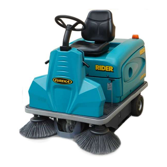
INTRODUCTION “EUREKA S.p.a.” , leader manufacturer of sweeping machines, is pleased to welcome you as an owner of the “RIDER 1201 EB” sweeper. We are sure that its use will give you great satisfaction and that while working with the RIDER 1201 EB you will have the opportunity to appreciate its quality, robustness, and versatility. -
Page 6: Machine Description
The machine and manufacturer are identified through three plates on the rear of the dirt container REFER TO THESE DETAILS WHEN ORDERING SPARE PARTS OR MAKING ANY OTHER ENQUIRY TO THE MANUFACTURER. EUREKA sweepers conform with the EEC directives and show the CE mark... -
Page 7: Warnings
OPERATE, ADJUST, CARRY OUT ORDINARY SERVICING, CLEAN, REPAIR AND TRANSPORT THE MACHINE. EUREKA Srl WILL NOT BE HELD LIABLE FOR ANY PROBLEMS, BREAKAGE, ACCIDENTS OR OTHER OCCURRENCES DUE TO THE IGNORANCE OF OR THE NON-APPLICATION OF THE PROCEDURES CONTAINED IN THIS MANUAL OR TO THE IMPROPER USE OF THE MACHINE. -
Page 8: General Warnings And Reccomandations
GENERAL WARNINGS AND RECCOMANDATIONS DANGER SIGNS - ATTENTION THIS SYMBOL HIGHLIGHTS ALL THE OPERATIONS THAT REPRESENT A POTENTIALLY HAZARDOUS SITUATION FOR THE OPERATOR IT IS THEREFORE NECESSARY TO ADHERE CLOSELY TO THE CONDITIONS SHOWN BY THIS SYMBOL DANGER OF BURNING DUE TO VERY HOT SURFACES. EAR PROTECTORS/PLUGS/MUFFLERS MUST BE WORN. - Page 9 EMERGENCY SITUATIONS ONLY FIGHT FIRES WITH POWDER FIRE EXTINGUISHERS CLEANING AND MAINTENANCE The machine must be cleaned by persons who have received proper instruction for the purpose, who know how to cut off the sources of energy and who know the characteristics of the machine so as not to find themselves in a hazardous situation.
- Page 10 PRECAUTIONS FOR THE SAFETY OF OPERATORS AND TECHNICIANS - The machine must not be used by non-authorised personnel who have not been trained to use it properly or by people who are under the influence of substances that could alter their nervous reflexes (alcohol, psycho pharmaceuticals, drugs etc.) - Do not use the machine in inflammable areas or where there is the danger of explosions - Do not collect material that is alight or anything else that could cause a fire.
- Page 11 UPDATING OF THE USER’S MANUAL When large-scale modifications are made to the machine or new parts are installed, the updated documentation must be sent to the Dealer along with the purchased part or as an update of the manual OBLIGATIONS OF THE EMPLOYER OR OWNER OF THE MACHINE The employer or owner of the machine is responsible for giving the User’s Manual to all the personnel who are going to have to use the machine.
-
Page 12: Disposal
DISPOSAL SPENT OILS Spent oils must not be thrown away into the environment under any circumstances. They must be given to authorised Collectors in compliance with the regulations currently in force. Temporary storage must be inside watertight containers with sealed lid to avoid contact with the environment and with rainwater. -
Page 13: Trasport - Handling
TRANSPORT TRANSPORT The machine must be fixed to a pallet to make it easier to transport. Eureka SRL packs the machine by removing the following components: -Steering wheel -Seat -Side brush Before dismounting it, please mount the steering wheel and the seat. - Page 15 RIDER 1201 EB RIGHT SIDE BRUSH GEAR MOTOR 2. SIDE BRUSHES 3. DRIVE WHEEL 4. LEFT SIDE BRUSH GEAR MOTOR 5. FRONT RUBBER 6. MAIN BRUSH 7. REAR RUBBER 8. LEFT SIDE BRUSH RUBBER 9. ELECTRIC SYSTEM BOX 10. BATTERY CONNECTOR 11.
-
Page 16: Primary Functions And Controls
PRIMARY FUNCTIONS AND CONTROLS CONTROLS ON THE MACHINE... - Page 17 VACUUM CLOSURE CONTROL 2. FILTER SHAKER BUTTON 3. BEEPER 4. MAIN BRUSH CONTROL 5. BRUSH/VACUUM MOTOR SWITCH 6. IGNITION KEY 7. SEAT ADJUSTMENT LEVER 8. LEFT SIDE BRUSH LEVER 9. RIGHT SIDE BRUSH LEVER 10. BRAKE LOCK (PARKING BRAKE) 11. FORWARD PEDAL 12.
- Page 18 VACUUM CLOSING CONTROL If the lever is in forward position (DRY) the vacuum is on If the lever is in back position (WET) the vacuum is off FILTER SHAKER BUTTON Press this button for few secons to enable the shaker filter. BEEPER MAIN BRUSH CONTROL Lower the lever to engage and lower the main brush.
- Page 19 LEFT SIDE BRUSH LEVER ------------------------------------- RIGHT SIDE BRUSH LEVER ------------------------------------- BRAKE LOCK (PARKING BRAKE) To activate the parking brake, press the pedal and push the locking brake knob. To release it, push slowly the brake pedal and push back the unlocking knob. DIRECTION OF MOVEMENT CONTROL By pressing the button forwards, forward movement is selected.
-
Page 20: Using The Machine
USING THE MACHINE EUREKA SWEEPERS MUST BE OPERATED BY PERSONNEL WHO ARE SUITABLY TRAINED AND AUTHORISED. THE SWEEPERS THAT ARE NOT IN FULL WORKING ORDER MUST BE REMOVED FROM SERVICE. THE SEAT IS FITTED WITH DIPSWITCH THAT PREVENTS IT BEING MOVED FORWARD OR BACK IF THE OPERATOR IS NOT SITTING IN THE DRIVING SEAT. -
Page 21: Setting
1. BRAKE PEDAL 2. LEFT SIDE BRUSH LEVER (OPTIONAL) 3. PARKING BRAKE CONTROL 4. KEY 5. CHOPPER OPERATION INDICATOR 6. RIGHT SIDE BRUSH LEVER 7. FORWARD PEDAL 8. VACUUM/BRUSH SWITCH 9. FORWARD MOVEMENT SWITCH 10. MAIN BRUSH LEVER Before starting the machine, make sure the main brush and the side brushes are raised from the ground (POS.2 POS.6 POS.10) Turn the key clockwise of a notch... -
Page 22: Recahrging The Battery
Switch off the machine and engage the parking brake After lifting the bonnet-seat, disconnect the connector pos. 1 from the machine and connect it to the battery charger pos. 2. Before charging the battery make sure you carefully follow the instructions in the battery charger manual provided with the machine;... -
Page 23: Replacing The Fuses
1. ELECTRIC PLAN BOX 2. SCREW 3. SPARE FUSE 50A 4. GENERAL FUSE 15A 5. TRACTION FUSE 50A 6. BRUSH/VECUUM MOTOR FUSE 50A 7. SPACER 8. INTERMITTENCE SHAKER FUSE 15A Lift the hood and block it by the apposite bar Remove the battery connector. - Page 24 VACUUM CLOSING KNOB SHAKER FILTER BUTTON MAIN BRUSH LEVER RIGHT SIDE BRUSH LEVER FRONT FLAP LEVER RIGHT SIDE BRUSH LEVER...
-
Page 25: Vacuum Closure Control
SHOULD YOU GO ACROSS A WET FLOOR OR A VACUUM CLOSING COURTYARD WITH PUDDLES, YOU MUST CLOSE THE CONTROL VACUUM, SO AS TO PROTECT THE POLYESTER FILTER. With the lever Pos. 1 forward (DRY), the vacuum is on Turn the lever back (WET), the vacuum is off. FILTER SHAKER Press the key downwards and turn it anti-clockwise;... -
Page 26: Battery Cable Lenght
BATTERY CABLE LENGTH N° COLOUR Ømm LENGTH (mm) BLACK... -
Page 27: Side Brush Control
1. RIGHT AND LEFT SIDE BRUSH LEVERS 2. FLANGE SCREW 3. FLANGE 4. MAIN SCREW RIGHT AND LEFT SIDE BRUSH Before starting up the brushes, make sure that there are no SIDE BRUSH CONTROL ropes, strings, wire or anything else wound around the brushes The side brush rises and is lowered by working the lever in pos. -
Page 28: Emptyng The Dirt Container
1. DIRT CONTAINER 2. DIRT CONATAINER WITH REFUSE BOXES KIT (OPTIONAL) After using the machine in dusty areas or with many debris, it is necessarìty to empty the dirt container. EMPTYING THE DIRT CONTAINER To empty it, please proceed as follows: Shake often the filter Turn off the engine and insert the parking brake Hold the dirt container using the handle (A) -
Page 29: Adjusting The Main Brush
ADJUSTING THE MAIN BRUSH Turn off the engine and insert the parking brake. Raise the main brush lever Open the left side door and remove the right side. Unloose the fixing screws of the main brush hubs If the brush is worn, move the hubs in the direction of the arrow (forward). - Page 30 1. MAIN BRUSH 2. MAIN BRUSH LEFT SUPPORT 3. LOCKING BUSH 4. LEFT SIDE DOOR 5. KEY 6. MAIN BRUSH LEVER...
-
Page 31: Main Brush Control
MAIN BRUSH CONTROL Before starting up the brushes, make sure that there are no ropes, strings, wire or anything else wound around the brushes The side brush rises and is lowered by working the lever in pos. 6: - when the lever is in pos A, the brush is raised and still. - when the lever is pos B, the brush is down and is turning. -
Page 32: Replacing The Right Side Rubber Flap
1. RIGHT PANEL FIXING SCREWS 2. RIGHT PANEL 3. REAR RUBBER FLAP FIXING METAL SHEET 4. REAR RUBBER FLAP 5. RIGHT RUBBER FLAP FRAME FIXING SCREWS 6. RIGHT RUBBER FLAP FIXING METAL SHEET 7. RIGHT RUBBER FLAP REPLACING THE RIGHT SIDE Remove the right side panel POS. -
Page 33: Replacing The Left Side Rubber Flap
1. RIGHT RUBBER FLAP FIXING METAL SHEET 2. RIGHT RUBBER FLAP 3. FIXING SCREW 4. FIXING LEVER NUT 5. COMPLETE FLAP 6. FRONT RUBBER FLAP FIXING METAL SHEET 7. FRONT RUBBER REPLACING THE LEFT SIDE Turn off the engine and insert the parking brake. -
Page 34: Replacing The Filter
FILTER COVER LOCKING BRACKET LOCKING FILTER COVER BAG FILTER SHAKER CONNECTOR SPACERS SHAKER LOCKING PLATES ON RODS FILTER SUPPORT RODS FITER SUPPORT REPLACING THE FILTER Carefully shake the filter Remove the key Raise the hood and lock it by the bar Remove the filter cover POS.1 Remove the plates POS.2 and the blocking mesh POS.3 Raise the filter and disconnect the connector POS.6... -
Page 35: Dimensional Drawings
DIMENSIONAL DRAWINGS... -
Page 36: Technical Chart
1560 mm Height including driver’s seat 1250 mm BRUSHES Main brush width and diameter 700 mm x 285 mm Rpm 500-520 (Rider 1201 EB) Side brush diameter Ø 500 mm Rpm 79 WEIGHT Weight RIDER 1201 E without batteries 305 Kg... - Page 37 OTHER CHARACTERISTICS Drive on front wheel Drum brakes on rear wheels 2 x Rear wheels 3004 ( full rubber, non Ø 250x80 marking ) 1 x Front wheel Rider 1201EB x 1: Ø 250x101 rubber, non- marking tyre NOISE: ELECTRIC MOTOR Average level of acoustic pressure Lpm=72.07 Db Acoustic power level:...
-
Page 38: Periodic Servicing
PERIODIC SERVICING REGULAR PERIODIC SERVICING YOUR SWEEPER GUARANTEES OUTSTANDING PERFORMANCE OF THE MACHINE AND ITS LONG LIFE. THE PAGES THAT FOLLOW CONTAIN THE INFORMATION THAT WILL HELP TO PLAN THE CARE AND THE SERVICING THAT THE MACHINE NEEDS. ATTENTION! DO NOT CARRY OUT ANY MAINTENANCE ON THE MACHINE OR ITS COMPONENTS WITHOUT HAVING FIRST TURNED IT OFF, ENGAGED THE HAND BRAKE, BLOCKED THE WHEELS AND DISCONNECTED THE CONNECTOR OF THE TRACTION BATTERY... -
Page 39: Ordinary Servicing
ORDINARY SERVICING RECOMMENDED SPARE PARTS USED FOR SERVICING. SERVICING OPERATIONS CAN BE CARRIED OUT BY THE USER HIMSELF ON CONDITON IT HAS PREVIOUSLY BEEN INSTRUCTED BY EITHER THE MACHINE OWNER OR HIS EMPLOYER - FRONT RUBBER FLAP P/N 350002 - RIGHT SIDE RUBBER FLAP P/N 340113 - LEFT SIDE RUBBER FLAP P/N. -
Page 41: Extraordinary Servicing
RIDER EB SWEEPER SERVICING AND MAINTENANCE 1° SCHEDULED SERVICING MONTH YEAR WORKING AFTER 50 HOURS DATE HOURS BRUSH MOTOR Clean the outside of the motor using compressed air, above all the slats located at the rear Clean above the carbons and manifold TRACTION MOTOR ... - Page 42 RIDER EB SWEEPER SERVICING AND MAINTENANCE 2° SCHEDULED SERVICING MONTH YEAR WORKING AFTER 100 HOURS DATE HOURS BRUSH MOTOR Clean the outside of the motor using compressed air, above all the slats located at the rear Clean above the carbons and manifold TRACTION MOTOR ...
- Page 43 RIDER EB SWEEPER SERVICING AND MAINTENANCE 3° SCHEDULED SERVICING MONTH YEAR WORKING AFTER 200 HOURS DATE HOURS BRUSH MOTOR Clean the outside of the motor using compressed air, above all the slats located at the rear Clean above the carbons and manifold TRACTION MOTOR ...
- Page 44 RIDER EB SWEEPER SERVICING AND MAINTENANCE 4° SCHEDULED SERVICING MONTH YEAR WORKING AFTER 300 HOURS DATE HOURS BRUSH MOTOR Clean the outside of the motor using compressed air, above all the slats located at the rear Clean above the carbons and manifold TRACTION MOTOR ...
- Page 45 RIDER EB SWEEPER SERVICING AND MAINTENANCE 5° SCHEDULED SERVICING MONTH YEAR WORKING AFTER 400 HOURS DATE HOURS BRUSH MOTOR Clean the outside of the motor using compressed air, above all the slats located at the rear Clean above the carbons and manifold TRACTION MOTOR ...
- Page 46 RIDER EB SWEEPER SERVICING AND MAINTENANCE 6° SCHEDULED SERVICING MONTH YEAR WORKING AFTER 500 HOURS DATE HOURS BRUSH MOTOR Clean the outside of the motor using compressed air, above all the slats located at the rear Clean above the carbons and manifold TRACTION MOTOR ...
- Page 47 CHECK AND MAINTENANCE SERVICES SWEEPER RIDER EB MONTH YEAR WORKING HOURS DATE AT 600 HOURS AS AFTER 100 HOURS THE SCHEDULED SERVICING WAS CARRIED OUT BY SEAL OR STAMP OF THE DEALER CARRYING OUT THE SCHEDULED NAME: _____________________________ SERVICING SURNAME: _____________________________ SIGNATURE:_____________________________ MONTH YEAR...
-
Page 48: Servicing And Maintenance For Scheduled Servicing
TROUBLE-SHOOTING CHART WARNING! ANY TYPE OF SERVICE OPERATION OR TEST, WITH THE EXCEPTION OF THOSE SHOWN IN THE ENGINE’S MANUAL OR THE BATTERY’S MANUAL, MUST BE CARRIED OUT BY AUTHORIZED SERVICE CENTRES ONLY. PROBLEM CAUSE SOLUTION With key on, warning lights don’t work Starting battery is flat Charge the battery Fuse is blown... - Page 49 The central brush fails to clean uniformly 14. Brush worn Replace it 15. Brush lifted Lower it 16. Miscellaneous material around brush Clean it 17. Wrong brush adjustment Adjust brush Flat battery 18. Battery in short-circuit Replace it 19. The battery charger doesn’t work Replace it or repair it The shaker doesn’t work 20.
-
Page 50: Product Warranty
RIDER EB PRODUCT WARRANTY Eureka Srl warrants that the RIDER EB will be free from defects in material and workmanship for a period of 12 months from date of installation. Written notice of any claimed defect must be given to Eureka Srl or its Authorized Sales/Service Representative within the warranty period and within thirty (30) days after such defect is discovered. - Page 51 Warranty claims will be evaluated only if the following Installation Form will be sent by fax or by mail, filled in all its parts, to Eureka’s headquarter within thirty (30) days after the machine’s installation. PLEASE RETAIN THE ORIGINAL COPY WITHIN THE MANUAL COMPANY &...
-
Page 52: Installation Form For Warranty Approval
Viale dell’Artigianato 30/32 35013 CITTADELLA (PD) dichiariamo sotto la nostra esclusiva responsabilità che il prodotto SPAZZATRICE: MODELLO: RIDER 1201 EB N°. TELAIO:__________________________________ al quale questa dichiarazione si riferisce è conforme alle seguenti norme: Sicurezza del macchinario, Concetti fondamentali, principi generali di progettazione Specifiche e principi tecnici - UNI EN 292-2(1991) + Modifica A1 (1995) ...
Need help?
Do you have a question about the RIDER 1201 EB and is the answer not in the manual?
Questions and answers