
Subscribe to Our Youtube Channel
Related Manuals for Gascat HORUS


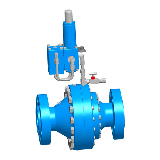
Summary of Contents for Gascat HORUS
- Page 1 Installation Manual, Maintenance and Operation Pressure Regulating Valve Model HORUS Spring to Close...
-
Page 2: Table Of Contents
Installation Manual, Maintenance and Operation MI-18 Pressure Regulating Valve – Model Horus INDEX 1.0 - GENERAL WARNINGS ................................3 1.1 – INSTRUCTIONS FOR COMMISSIONING ............................ 3 1.2 – HEALTH AND SAFETY ................................3 1.2.1 – NOISE ....................................3 1.2.2 – INSTALLATION ................................. 3 1.2.3 –... -
Page 3: General Warnings
If any doubts or ambiguities that affect the proper procedures ask Gascat Ind e Com. Ltda. who will be happy to advise or provide the relevant service or instruction. -
Page 4: Operation
The pressure regulator HORUS is pilot operated and has axial flow what result in low noise level as well high flow capacity. Beyond this, the double diaphragm pilots supplied with the valve allow accuracy in set pressure up to 1%. -
Page 5: Specifications
Installation Manual, Maintenance and Operation MI-18 Pressure Regulating Valve – Model Horus 2.3 SPECIFICATIONS 2.3.1 AVAILABLE SETTINGS HORUS FC: Pilot operated pressure regulator fail close position 2.3.2 AVAILABLE CONNECTIONS FLANGE ASME B16.5 FLANGE DIN 2634 / 2635 2” 150#RF / 300#RF / 600#RF ou RTJ / 900#RF ou RTJ PN 25 / PN 40 3”... -
Page 6: Approximate Weight
2.3.7 SET-POINT Pressure regulators, model HORUS use two models of pilots for pressure control called G-40 and G-42, here are the adjustment ranges available for each model:... -
Page 7: Accuracy And Lock Up
Installation Manual, Maintenance and Operation MI-18 Pressure Regulating Valve – Model Horus PILOT G-42 SPRING COLOR CODE ADJUSTMENT RANGE GREEN 01.49.65 1,0 – 4,5 bar GRAY 01.49.64 4,5 – 12,0 bar BLUE 01.49.33 11,0 – 17,0 bar 01.51.94A 16,0 – 30,0 bar YELLOW 01.51.94... - Page 8 Installation Manual, Maintenance and Operation MI-18 Pressure Regulating Valve – Model Horus FIGURE 1 - HORUS FAIL CLOSED Elaborate Verified / Approved Date Review Page J.Junior Celso Nieto 25/11/16 8 de 32...
-
Page 9: Booster (G-43)
Installation Manual, Maintenance and Operation MI-18 Pressure Regulating Valve – Model Horus 3.2 BOOSTER (G-43) The Booster is nothing more than a pre-regulator that automatically adjusts the process conditions as a function of the input pressure and output pressure with the purpose of reducing the pilot inlet pressure, allowing the pilot to operate in a milder condition, thus eliminating any chance of interference on the regulator piloting by the input pressure variation. -
Page 10: Pilots (G-40 & G-42)
Installation Manual, Maintenance and Operation MI-18 Pressure Regulating Valve – Model Horus 3.3 PILOTS (G-40 & G-42) The pilots series G-40 and G-42 are composed by dual diaphragm pilot that can achieve much higher accuracy than other pilots due to their constructional characteristics. -
Page 11: Filters
The HORUS pressure regulators are available with F-10 filter, mounted separate from the pilot block or compact version with the filter element already attached to the pre regulator. -
Page 12: Sense
Each throttle model HORUS SC (FF) needs three process connections: one directly to the actuator on the diaphragm, one that will be connected directly below the pilot and a third for the purpose of discharging the actuator under the diaphragm. -
Page 13: Scheme Recommended Installation
4 – Automatic shut-off valve for over pressure (SSV) 9- Output block valve 5 – Pressure regulator valve model URANO GASCAT Note: The position indicated for the sensor outlet may be less than 5D from the installation project to be reviewed and approved by engineering GASCAT. -
Page 14: Start-Up
The model HORUS valves are not sent to field set on their set-point, this measure tends to preserve the life of the product's internal therefore to... -
Page 15: Commissioning (Single Regulator)
HORUS model regulator commissioning a simple adjustment line, considering that the recommendations made in section 4.6.1 of this manual have been properly observed. The procedure in question considers the use of GIPS-FC GASCAT model valves as a safety device. 1) Fec Close the vent valve. -
Page 16: Adjusting The Line Booking
PS x 1,250 Note: The values in this table are recommendations based on best practices, but it is not prohibited the use of set- points in different groups of informed upon review and approval of GASCAT. Elaborate Verified / Approved... -
Page 17: List Of Recommended Tools
(impurities), natural wear and failures during operation of the equipment. It is important to keep in mind that the operation and maintenance of GASCAT equipment must be only carried out by highly qualified and trained personnel, preferably by staff trained by GASCAT instructors. - Page 18 Installation Manual, Maintenance and Operation MI-18 Pressure Regulating Valve – Model Horus Adjust the unloading valve (needle) .Check state shutter and anti-friction rings proceeding Shutter (pos 48 SC; pos 57 SO) of replacement or cleaning if the locked main regulator...
-
Page 19: Maintenance
Before starting maintenance pressure regulators in GASCAT always make sure to have a replacement kit with original parts GASCAT as well as this instruction manual for reference and how to safely and efficiently while maintaining the equipment. -
Page 20: Recommended Repair Parts And Kits
Installation Manual, Maintenance and Operation MI-18 Pressure Regulating Valve – Model Horus 6.1 RECOMMENDED REPAIR PARTS AND KITS HORUS SC (FF) Elaborate Verified / Approved Date Review Page J.Junior Celso Nieto 25/11/16 20 de 32... - Page 21 Installation Manual, Maintenance and Operation MI-18 Pressure Regulating Valve – Model Horus HORUS SC (FF) POS. DESCRIPTION 1" 2" 3" 4" 6" 8" DIAPHRAGM POSITION INDICATION DISPLAY O'RING O'RING O'RING O'RING O'RING O'RING O'RING O'RING Elaborate Verified / Approved Date...
- Page 22 Installation Manual, Maintenance and Operation MI-18 Pressure Regulating Valve – Model Horus BOOSTER G-43 + PILOT G-42/40 Elaborate Verified / Approved Date Review Page J.Junior Celso Nieto 25/11/16 22 de 32...
- Page 23 Installation Manual, Maintenance and Operation MI-18 Pressure Regulating Valve – Model Horus BOOSTER G-43 POS. DESCRIÇÃO GARRISON DIAPHRAGM O'RING O'RING O'RING O'RING O'RING PILOTO G-40/42 POS. DESCRIÇÃO DIAPHRAGM O'RING O'RING O'RING SHUTTER BOOSTER G-43 + PILOTO G-42/40 Elaborate Verified / Approved...
- Page 24 Installation Manual, Maintenance and Operation MI-18 Pressure Regulating Valve – Model Horus G-80 PILOT → CODE: 28.21.28A_KIT POS. DESCRIPTION QTY POS. DESCRIPTION RELIEF O'RING DIAPHRAGM O'RING DIAPHRAGM O'RING SHUTTER O'RING SHUTTER O'RING INTERNAL RELIEF O'RING FILTER ELEMENT O'RING GASKET O'RING...
-
Page 25: Procedure For Removal The Pilot G-40 / 42
Installation Manual, Maintenance and Operation MI-18 Pressure Regulating Valve – Model Horus 6.2 PROCEDURE FOR PILOT REMOVAL G-40/42 1) Before proceeding with the disassembly of the equipment check if all the conditions set out in item 4.6.1 of this manual have been observed. - Page 26 Installation Manual, Maintenance and Operation MI-18 Pressure Regulating Valve – Model Horus 9) Remove the bushing (item 34/31) shutter spring. 10) Remove the obturator (pos 29/26) 11) Remove the diaphragm plate and the lower diaphragm (pos 9/11), turn the steering block to the starting position and proceed with the removal of the plug (pos 35/32).
-
Page 27: Procedure For Assembly The Pilot G-40 / 42
Installation Manual, Maintenance and Operation MI-18 Pressure Regulating Valve – Model Horus 6.3 PROCEDURE FOR PILOT ASSEMBLY G-40/42 To perform the assembly of the G-42 pilot just follow the steps reported in the back disassembly procedure forward starting with the assembly's headquarters, but would like to make two observations on two specific points that must be evaluated thoroughly during the pilot reassembly. -
Page 28: Procedure For Removal Booster (Pre-Regulator) G-43
Installation Manual, Maintenance and Operation MI-18 Pressure Regulating Valve – Model Horus Marking the body counterclockwise Diaphragm marking between the two Marking the body clockwise 3) diaphragms (pos 9/11) G-42 are shaped pilot therefore have a correct mounting position and it should be... - Page 29 Installation Manual, Maintenance and Operation MI-18 Pressure Regulating Valve – Model Horus 1) Remove the cover (pos 39) and the diaphragm assembly (item 28). 2) Lock the shaft (pos 28), release the nut (pos 11), remove the disc springs (pos 12) and the lower diaphragm plate (item 27) to release the diaphragm (pos 10).
- Page 30 Installation Manual, Maintenance and Operation MI-18 Pressure Regulating Valve – Model Horus 3) Now let's move to dismantle the bottom of the booster, so the ideal is that it is rotated so that the bottom is face up, made it proceed with the removal of the door trim (pos 45).
-
Page 31: Procedure For Assembly Booster (Pré Regulator) G-43
Installation Manual, Maintenance and Operation MI-18 Pressure Regulating Valve – Model Horus 5) Remove the shaft guide (item 40) and the thrust bushing (item 41) 6.5 PROCEDURE FOR BOOSTER ASSEMBLY (PRE REGULATOR) G-43 To perform the assembly of the booster G-43 just follow the steps reported in the back disassembly procedure forward starting with the assembly's headquarters, but would like to make some observations on some specific points that must be evaluated thoroughly during reassembly of the booster. -
Page 32: List Of Recommended Tools For Maintenance
Installation Manual, Maintenance and Operation MI-18 Pressure Regulating Valve – Model Horus 6.6 LIST OF RECOMMENDED TOOLS FOR MAINTENANCE TOOLS DIMENSIONS KEY COMBINED 5/8”,3/4”, 1”, 1-1/8”, 2”, 13mm ALLEN KEY 6mm, 1/4" COMPASS KEY Elaborate Verified / Approved Date Review Page J.Junior...
Need help?
Do you have a question about the HORUS and is the answer not in the manual?
Questions and answers