Table of Contents

Subscribe to Our Youtube Channel
Related Manuals for Premier Mounts MVW55


Summary of Contents for Premier Mounts MVW55
- Page 1 INSTALLATION INSTRUCTIONS MVW55 / MVW554UNS Video Wall Frame NORTH AMERICA 1321 S. State College Blvd. Fullerton, CA 92831 USA Phone: 1.800.368.9700 Fax: 1.800.832.4888 Other Locations Phone: (001).714.632.7100 Fax: (001).714.632.1044...
-
Page 2: Table Of Contents
Premier Mounts does not warrant against damage caused by the use of any Premier Mounts product for purposes other than those for which it was designed or damage caused by unauthorized attachments or modifications, and is not responsible for any damages, claims, demands, suits, actions or causes of action of whatever kind resulting from, arising out of or in any manner relating to any such use, attachments or modifications. -
Page 3: Installation Tools
MVW55 / MVW554UNS(s) Parts List Make sure your Premier Mounts product has the following hardware and components before beginning installation. If there are parts missing and/or damaged, stop the installation and call Premier Mounts at (800) 368-9700. MVW55 / MVW554UNS Hardware... -
Page 4: Features
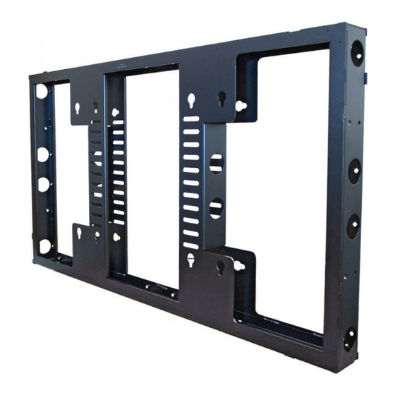
MVW55 / MVW554UNS Features The MVW55 / MVW554UNS Video Wall Frame is designed for mounting the NEC X551UN to Premier Mounts’ dual- pole carts and stands, or flying them from above. They can be installed in either portrait or landscape orientation. Quick- release buttons make it easier than ever to install the displays, which can be attached to the front and/or back of the MVW55 / MVW554UNS. -
Page 5: Installing The Mvw55 / Mvw554Uns
Introduction The Premier Mounts MVW55 / MVW554UNS Video Wall Frame is designed for use with Premier Mounts’ dual-pole carts and stands, as well as for flying from above. You may use one MVW55 / MVW554UNS as a standalone mount, or multiple MVW55 / MVW554UNS’s to create a video wall display. - Page 6 If you are fastening multiple MVW55 / MVW554UNS’s, use the M8 x 16mm pan Phillips screws provided to fasten them together from inside the frames (Figure 1). To safely install rows of multiple MVW55 / MVW554UNS’s, fasten them first in individual rows, then insert the tubing of the dual-pole cart or stand into each row.
- Page 7 Slide the MVW55 / MVW554UNS to the desired height on the dual-pole cart or stand. Insert four (4) M8 x 16mm set screws into the MVW55 / MVW554UNS screw holes near the tubing (see drawing). Tighten the screws against the MVW55 / MVW554UNS and tubing.
-
Page 8: Flying Installation
The steel tube must be long enough to span the entire width of the frame(s) (Figure 2). Make sure the MVW55 / MVW554UNS keyhole mounting slots point down so that they can support the flat-panel display(s) later (Figure 3). Illustrations show only some of... - Page 9 MVW55 / MVW554UNS’s together. Figure 1 If you are fastening multiple MVW55 / MVW554UNS’s, use the M8 x 16mm pan Phillips screws provided to fasten them together from inside the frames (Figure 1). To safely install rows of multiple MVW55 / MVW554UNS’s, fasten them first in individual rows, then fasten the rows together. After that, insert the heavy-duty plastic tube (Figure 2).
- Page 10 MVW55 / MVW554UNS. Step 5 Keyhole Mounting Attach the flat-panel display to either side of the MVW55 / MVW554UNS by Slot inserting the display’s quick-release buttons into the keyhole mounting slots on the MVW55 / MVW554UNS, locking them into place.
-
Page 11: Technical Specifications
2.19 3.36 2x 47.88 16.07 16.07 2X 15.75 2x 15.75 REAR VIEW 23.62 1.00 FRONT VIEW 1.00 DETAIL A DETAIL B SCALE 1 : 2 SCALE 1 : 2 Installation Instructions Page 11 Visit the Premier Mounts website at http://www.mounts.com... -
Page 12: Warranty
Disclaimer Premier Mounts intends to make this manual accurate and complete. However, Premier Mounts makes no claim that the information contained herein covers all details, conditions or variations, nor does it provide for every possible contingency in connection with the installation or use of this product. The information contained in this document is subject to change without notice or obligation of any kind.
Need help?
Do you have a question about the MVW55 and is the answer not in the manual?
Questions and answers