Table of Contents
Advertisement
Quick Links
INSTALLATION INSTRUCTIONS
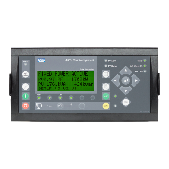
Automatic Sustainable Controller
● Mounting
● Board slot positions
● Terminal strip overview
● I/O lists
● Wiring
DEIF A/S · Frisenborgvej 33 · DK-7800 Skive · Tel.: +45 9614 9614 · Fax: +45 9614 9615 · info@deif.com · www.deif.com
ASC
Document no.: 4189341076B
SW version: 4.05.x or later
Advertisement
Table of Contents

Related Manuals for Deif ASC


Summary of Contents for Deif ASC
- Page 1 ● Wiring DEIF A/S · Frisenborgvej 33 · DK-7800 Skive · Tel.: +45 9614 9614 · Fax: +45 9614 9615 · info@deif.com · www.deif.com isenborgvej 33 · DK-7800 Skive · Tel.: +45 9614 9614 · Fax: +45 9614 9615 · info@deif.com · www.deif.com Document no.: 4189341076B...
-
Page 2: Table Of Contents
2.8.1. Combination (off-grid + grid-tied), power management............... 12 2.9. Combination (off-grid + grid-tied), stand-alone..................13 2.9.1. Combination (off-grid + grid-tied), stand-alone................13 3. Mounting 3.1. ASC mounting and dimensions......................14 3.1.1. Mounting of the unit........................14 3.1.2. Unit dimensions........................... 14 3.1.3. Panel cutout..........................15 3.1.4. - Page 3 5.2.4. Multi-inputs (102, 105, 108)......................36 5.2.5. Transistor outputs (open collector outputs)................. 38 5.3. Communication............................ 39 5.3.1. CANbus............................39 5.3.2. Modbus (option H2)........................40 5.3.3. Display cable (option J)....................... 42 6. Technical information 6.1. Technical specifications, ASC......................43 DEIF A/S Page 3 of 47...
-
Page 4: General Information
1.1.2 Legal information and disclaimer DEIF takes no responsibility for installation or operation of the generator set. If there is any doubt about how to install or operate the engine/generator controlled by the Multi-line 2 unit, the company responsible for the installation or the operation of the set must be contacted. -
Page 5: Factory Settings
ASC installation instructions 4189341076 General information 1.1.5 Factory settings The Multi-line 2 unit is delivered from factory with certain factory settings. These are based on average values and are not necessarily the correct settings for matching the engine/generator set in question. Precautions must be taken to check the settings before running the engine/generator set. -
Page 6: General Product Information
The concept of the ASC is to offer a cost-effective solution to EPCs and other parties in the solar energy field, who need a flexible generator protection and control unit for medium to large PV applications. As the ASC is part of the Multi-line product family, the standard functions can be supplemented with a variety of optional functions. -
Page 7: Standard And Optional Applications
Selectable output commands 2.3 Standard and optional applications In the following sections, the standard and optional applications of the ASC will be presented, this includes off-grid modes, grid-tied modes and combination modes, (off-grid combined with grid-tied possibilities (MB open or closed). -
Page 8: Off-Grid Applications, Power Management
This application is used if the gensets already have a control system on top of them (referred to as “Control- ler” in the picture). The ASC needs inputs from the GB positions (closed) and the produced active and reactive power, represen- ted by analogue 4 to 20 mA signals. - Page 9 ASC installation instructions 4189341076 General product information Setting in ASC Setting 6071 Operating mode Island operation Island operation DEIF A/S Page 9 of 47...
-
Page 10: Grid-Tied Applications, Power Management
2.6 Grid-tied applications, power management 2.6.1 Grid-tied applications, power management This application is using the CAN bus power management link between the DEIF controllers in the system. Thereby it is not necessary to install additional hardwiring between the ASC and the gensets. -
Page 11: Grid-Tied, Stand-Alone
This application is used if no AGC mains is installed to facilitate the power management parallel to mains functions. The ASC needs inputs from the MB positions (open/closed) and the produced active/reactive pow- er from the mains incomer or outgoing. This is represented by analogue 4 to 20 mA signals. -
Page 12: Combination (Off-Grid + Grid-Tied), Power Management
This application is used when the application has to be available in grid-tied modes as well as off-grid (islan- ded modes). In this example, the CAN bus link is wired between the AGC mains, AGC gensets and the ASC. It is not necessary to introduce other additional measurements or hardwiring since all necessary data is avail- able on the CAN bus for power management. -
Page 13: Combination (Off-Grid + Grid-Tied), Stand-Alone
ASC installation instructions 4189341076 General product information 2.9 Combination (off-grid + grid-tied), stand-alone 2.9.1 Combination (off-grid + grid-tied), stand-alone This application is used when the application has to be available in grid-tied modes as well as off-grid (islan- ded modes). In this example, third party controllers are installed (referred to as “Controller” in the picture) and therefore it is necessary to hardwire signals from the breaker positions (GBs and MB) and measure the mains power and reactive power, the summated genset power and the summated genset re-active power. -
Page 14: Mounting
ASC installation instructions 4189341076 Mounting 3. Mounting 3.1 ASC mounting and dimensions 3.1.1 Mounting of the unit The unit is designed for mounting inside the panel. The display can be installed on the panel door and con- nected to the main unit with a display cable. -
Page 15: Panel Cutout
ASC installation instructions 4189341076 Mounting 3.1.3 Panel cutout In order to ensure optimum mounting, the panel door must be cut out according to the panel cutout illustra- tion. 174.0 26.0 26.0 Required space 222X115mm Gasket outer 186X77mm Screws for fastning: 3.5mm selfcutting threads... -
Page 16: Drilling Template In Mm (Inches)
1. Directly mounted on a DIN rail. 2. Fastened with screws to the rear side of the cabinet. Six screw holes are available for this mounting method. DEIF recommends using the screw hole fastening. 3.1.6 Tightening torques Controller unit: 1.5 Nm for the six M4 screws (countersunk screws are not to be used) Plug connections (terminals): 0.5 Nm, 4.4 lb-in... - Page 17 ASC installation instructions 4189341076 Mounting 220.0 (8.661) 0.2 Nm Display 9P Female Sub 0 connector 0.7 Nm Screw M3 Max. 10 mm Bossard BN5687 Min. 6 mm or similar 20.0 (0.787) DEIF A/S Page 17 of 47...
-
Page 18: Hardware
ASC installation instructions 4189341076 Hardware 4. Hardware 4.1 Board slot positions The unit housing is divided into board slot positions. This means that the unit consists of a number of printed circuit boards (PCBs) mounted in numbered slots. The green terminal blocks are then mounted in the PCBs. -
Page 19: Unit Top Side Overview
ASC installation instructions 4189341076 Hardware 4.2 Unit top side overview 4.2.1 Unit top side overview An overview of the terminals is presented below. The slot positions are as follows: 53 54 56 57 59 60 61 62 63 65 66... - Page 20 ASC installation instructions 4189341076 Hardware DEIF A/S Page 20 of 47...
- Page 21 ASC installation instructions 4189341076 Hardware DEIF A/S Page 21 of 47...
-
Page 22: Input/Output Lists
ASC installation instructions 4189341076 Hardware 4.4 Input/output lists In the I/O lists, the following terms will be used in connection with the relay outputs: NO means Normally Open NC means Normally Closed NE means Normally Energised ND means Normally Deenergised Com. -
Page 23: Slot #1, Power Supply Pcb
ASC installation instructions 4189341076 Hardware 4.4.1 Slot #1, power supply PCB Term. Function Technical data Description +12/24 V DC 12/24 V DC Power supply +/-30 % 0 V DC Status relay Normally open relay, 24 V DC/1 A processor/power supply Com. -
Page 24: Slot #2, Serial Communication (Standard)
ASC installation instructions 4189341076 Hardware Term. Function Technical data Description Com. Common Common for terminals 23 to 27 4.4.2 Slot #2, serial communication (standard) Modbus (option H2.2) Term. Function Description DATA + (A) Modbus RTU, RS-485 This is the Modbus master output... -
Page 25: Slot #2, Relay Outputs (Option M14.2)
ASC installation instructions 4189341076 Hardware 4.4.4 Slot #2, relay outputs (option M14.2) Term. Function Technical data Description NE/ND Relay 29 Configurable 250 V AC/5 A Com. NE/ND Relay 31 Configurable 250 V AC/5 A Com. NE/ND Relay 33 Configurable 250 V AC/5 A Com. -
Page 26: Slot #3, 13 Binary Inputs And 4 Relay Outputs (Standard/M12)
ASC installation instructions 4189341076 Hardware 4.4.5 Slot #3, 13 binary inputs and 4 relay outputs (standard/M12) Term. Function Technical data Description Not used -10/+10 V DC Analogue I/O f/P set point Com. Common Common -10/+10 V DC Analogue I/O U/Q set point... -
Page 27: Slot #4, 7 Digital Inputs (Option M13.4)
ASC installation instructions 4189341076 Hardware 4.4.6 Slot #4, 7 digital inputs (option M13.4) Term. Function Technical data Description Binary input 65 Optocoupler Configurable Binary input 66 Optocoupler Configurable Binary input 67 Optocoupler Configurable Binary input 68 Optocoupler Configurable Binary input 69... -
Page 28: Slot #5, Ac Measuring
ASC installation instructions 4189341076 Hardware 4.4.9 Slot #5, AC measuring Term. Function Technical data Description I L1, s1 PV current L1 x/1 A or x/5 A input I L1, s2 I L2, s1 PV current L2 x/1 A or x/5 A input... -
Page 29: Slot #6, 4 Relay Outputs (Option M14.6)
ASC installation instructions 4189341076 Hardware 4.4.11 Slot #6, 4 relay outputs (option M14.6) Term. Function Technical data Description NE/ND Relay 90 Configurable 250 V AC/5 A Com. NE/ND Relay 92 Configurable 250 V AC/5 A Com. NE/ND Relay 94 Configurable 250 V AC/5 A Com. -
Page 30: Slot #7, I/O Interface Card (Standard/M4)
ASC installation instructions 4189341076 Hardware 4.4.14 Slot #7, I/O interface card (standard/M4) Term. Function Technical data Description +12/24 V DC 12/24 V DC DC power supply +/-30 % 0 V DC Not used 0(4) to 20 mA Digital Multi-input 1... -
Page 31: Slot #8, Serial Communication (Option H2.8)
ASC installation instructions 4189341076 Hardware Term. Function Technical data Description CAN-H CAN bus interface B CAN-L 4.4.15 Slot #8, serial communication (option H2.8) Term. Function Description DATA + (A) Modbus RTU, RS-485 This is the Modbus master output for power meter communication... -
Page 32: Slot #8, 4 Relay Outputs (Option M14.8)
ASC installation instructions 4189341076 Hardware 4.4.17 Slot #8, 4 relay outputs (option M14.8) Term. Function Technical data Description NE/ND Relay 126 Configurable 250 V AC/5 A Com. NE/ND Relay 128 Configurable 250 V AC/5 A Com. NE/ND Relay 130 Configurable 250 V AC/5 A Com. -
Page 33: Wirings
ASC installation instructions 4189341076 Wirings 5. Wirings 5.1 AC connections The Multi-line 2 unit can be wired up in 1-phase, 2-phase or 3-phase configuration. Contact the switchboard manufacturer for accurate information about required wiring for the specific application. 5.1.1 Neutral line (N) When 3-phase distribution systems are used, the neutral line (N) is only necessary if it is a 3-phase + neutral system. -
Page 34: 3-Phase Wiring
ASC installation instructions 4189341076 Wirings 5.1.5 3-phase wiring The diagram shows the most important points to wire, and it shows the example where the PV breaker is in- stalled, but this is optional. General wiring arrangement 5.2 DC connections 5.2.1 Digital inputs... -
Page 35: Analogue Inputs (Option M15.X)
ASC installation instructions 4189341076 Wirings 12/24V DC 12/24V DC Switch Multi-line 2 Multi-line 2 Switch 28 (COM.) 28 (COM.) Emergency stop: 12/24V DC Multi-line 2 99 (COM.) 0V DC 5.2.2 Analogue inputs (option M15.X) 4 to 20 mA Active transducer... -
Page 36: External Set Points
ASC installation instructions 4189341076 Wirings Passive transducer Multi-line 2 4-20 mA transducer +12/24V DC Analogue input 91 Measurement 0V DC 90 (Common) V DC sensor Multi-line 2 0-10V DC Analogue input 91 sensor 90 (Common) R = 450 Ω 5.2.3 External set points The set point inputs are passive;... - Page 37 ASC installation instructions 4189341076 Wirings Active transducer Multi-line 2 4-20 mA transducer +12/24V DC + Out Multi-input 0V DC Measurement - Out Passive transducer Multi-line 2 4-20 mA transducer +12/24V DC Multi-input 0 V DC If the passive sensor has its own battery supply, the voltage must not exceed 30 V DC.
-
Page 38: Transistor Outputs (Open Collector Outputs)
ASC installation instructions 4189341076 Wirings 1-wire 2-wire Multi-line 2 Multi-line 2 Multi-input Multi-input 0 to 40 V DC Battery Multi-line 2 0-40V DC Multi-input 0V DC 5.2.5 Transistor outputs (open collector outputs) The open collector outputs can be used as kWh and kvarh counter outputs or as relay outputs. The outputs are low power outputs. -
Page 39: Communication
Maximum load on the open collector outputs is 10 mA at 24 V DC. 5.3 Communication 5.3.1 CANbus Examples with three controllers connected, for example one ASC and two generator AGC units. It is not possible to mix CAN bus interface A and B. Multi-line 2... -
Page 40: Modbus (Option H2)
ASC installation instructions 4189341076 Wirings End resistor R = 120 Ohm. 5.3.2 Modbus (option H2) Connection with 2-wire screened cable: Use shielded twisted cable. The RS-485 Modbus lines need end resistors (end terminators) when the bus length exceeds 30 m. If end resistors are needed, we recommend to install them like this:... - Page 41 ASC installation instructions 4189341076 Wirings Multi-line 2 Multi-line 2 Multi-line 2 133 1 32 131 133 1 32 131 133 1 32 131 Option H2.8 terminals Option H2.2 terminals 1nF (50V) 120ohms 1/4W 1nF (50V) 120ohms 1/4W PLC or oth er device Cable: Belden 3105 A or equivalent.
-
Page 42: Display Cable (Option J)
ASC installation instructions 4189341076 Wirings 5.3.3 Display cable (option J) A standard computer extension cable can be used (9-pole SUB-D male/female plugs) or a cable can be tail- ored. Connect shield to plug metallic casing 9-p SUB D 9-p SUB D... -
Page 43: Technical Information
ASC installation instructions 4189341076 Technical information 6. Technical information 6.1 Technical specifications, ASC Accuracy Class 1.0 -25 to 15 to 30 to 70 °C Temperature coefficient: +/-0.2 % of full scale per 10 °C Class 0.5 with option Q1 Positive, negative and zero sequence alarms: class 1 within 5 % voltage unbalance Class 1.0 for negative sequence current... - Page 44 ASC installation instructions 4189341076 Technical information Binary inputs Optocoupler, bi-directional ON: 8 to 36 V DC Impedance: 4.7 kΩ OFF: <2 V DC Analogue in- -10 to +10 V DC: not galvanically separated. Impedance: 100 kΩ (G3) puts 0(4) to 20 mA: impedance 50 Ω. Not galvanically separated (M15.X) RPM (MPU): 2 to 70 V AC, 10 to 10000 Hz, max.
- Page 45 ASC installation instructions 4189341076 Technical information Mounting DIN rail mount or base mount with six M4 screws Tightening 1.5 Nm for the six M4 screws (countersunk screws are not to be used) torque DEIF A/S Page 45 of 47...
- Page 46 ASC installation instructions 4189341076 Technical information Safety To EN 61010-1, installation category (over-voltage category) III, 600 V, pollution degree 2 To UL 508 and CSA 22.2 no. 14-05, over-voltage category III, 600 V, pollution degree 2 EMC/CE To EN 61000-6-2, EN 61000-6-4, IEC 60255-26 Vibration 3 to 13.2 Hz: 2 mmpp.
- Page 47 ASC installation instructions 4189341076 Technical information Weight Base unit: 1.6 kg (3.5 lbs) Option J1/J4/J6/J7: 0.2 kg (0.4 lbs) Option J2: 0.4 kg (0.9 lbs) Option J8: 0.3 kg (0.58 lbs) Display: 0.4 kg (0.9 lbs) DEIF A/S Page 47 of 47...
Need help?
Do you have a question about the ASC and is the answer not in the manual?
Questions and answers