Siemens SINUMERIK 840D sl Operating Manual
Hmi sl universal
Hide thumbs
Also See for SINUMERIK 840D sl:
- Function manual (2184 pages) ,
- Programming manual (1334 pages) ,
- Commissioning manual (1102 pages)
Table of Contents
Advertisement
Quick Links
SINUMERIK 840D sl HMI sl Universal
SINUMERIK 840D sl
HMI sl Universal
Operating Manual
Valid for
SINUMERIK 840D sl/840DE sl control system
Software
NCU system software for 840D sl/840DE sl
with HMI sl
01/2008
6FC5398-6AP10-2BA0
Foreword
______________
Introduction
______________
Setting up the machine
______________
Machine the workpiece
______________
User data
______________
Teaching in a program
______________
Tool management
______________
Program management
______________
HT 8
Alarm, error, and system
______________
messages
______________
Appendix
Version
2.5
2.5
1
2
3
4
5
6
7
8
9
A
Advertisement
Table of Contents

Related Manuals for Siemens SINUMERIK 840D sl


Summary of Contents for Siemens SINUMERIK 840D sl
- Page 1 Foreword SINUMERIK 840D sl HMI sl Universal ______________ Introduction ______________ Setting up the machine SINUMERIK 840D sl ______________ Machine the workpiece HMI sl Universal ______________ User data ______________ Teaching in a program Operating Manual ______________ Tool management ______________ Program management...
- Page 2 Trademarks All names identified by ® are registered trademarks of the Siemens AG. The remaining trademarks in this publication may be trademarks whose use by third parties for their own purposes could violate the rights of the owner.
-
Page 3: Foreword
The Internet version of DOConCD (DOConWEB) is available at: http://www.automation.siemens.com/doconweb Information about training courses and FAQs (Frequently Asked Questions) can be found at the following website: http://www.siemens.com/motioncontrol under menu option "Support" Target group This documentation is intended for users of universal machines running the HMI sl software. Benefits The Operating Manual familiarizes users with the control elements and commands. - Page 4 Note Country-specific telephone numbers for technical support are provided under the following Internet address: Enter http://www.siemens.com/automation/service&support Calls are subject to charge, e.g. 0.14 €/min. on the German landline network. Tariffs of other phone companies may differ. Questions about the Operating Manual...
-
Page 5: Table Of Contents
Table of contents Foreword ..............................3 Introduction.............................. 11 Product overview .........................11 Operator panel fronts ........................12 1.2.1 Overview ............................12 1.2.2 Keys of the operator panel......................13 Machine control panels ........................15 1.3.1 Overview ............................15 1.3.2 Controls on the machine control panel ..................15 Operator interface ........................18 1.4.1 Screen layout ..........................18 1.4.2... - Page 6 Table of contents 2.5.6 Deleting a work offset........................56 Monitoring axis and spindle data ....................57 2.6.1 Specify working area limitations....................57 2.6.2 Editing spindle data........................58 Manual mode ..........................59 2.7.1 General............................59 2.7.2 Selecting a tool and spindle ......................59 2.7.2.1 T, S, M windows..........................
- Page 7 Table of contents 3.9.2 Searching in programs.........................95 3.9.3 Replacing program text........................96 3.9.4 Copying/pasting/deleting program blocks..................97 3.9.5 Renumbering a program ......................98 3.9.6 Editor settings ..........................99 3.10 Simulating machining.........................101 3.10.1 Overview ............................101 3.10.2 Simulation prior to machining of the workpiece .................102 3.10.2.1 Start simulation ..........................103 3.10.3 Simultaneous recording prior to machining of the workpiece ............103 3.10.3.1 Starting simultaneous recording ....................104...
- Page 8 Table of contents Overview ........................... 133 General sequence........................133 Inserting a block ........................134 5.3.1 Teach-in via Windows ....................... 135 5.3.1.1 General information........................135 5.3.1.2 Teach in rapid traverse G0......................136 5.3.1.3 Teach in straight G1........................136 5.3.1.4 Teaching in circle intermediate and circle end point CIP............137 5.3.1.5 A-spline teach in (option) ......................
- Page 9 Table of contents 7.4.5 Creating a Joblist ........................186 7.4.6 Creating a program list.......................187 Creating templates........................189 Displaying the program in the Preview..................190 Selecting several directories/programs..................190 Copying and pasting a directory/program..................192 Deleting a directory/program......................194 7.10 Changing file and directory properties ..................195 7.11 Backing up data .........................195 7.11.1...
- Page 10 Table of contents HMI sl Universal Operating Manual, 01/2008, 6FC5398-6AP10-2BA0...
-
Page 11: Introduction
Introduction Product overview The SINUMERIK controller is a CNC (Computerized Numerical Controller) for machine tools. You can use the CNC to implement the following basic functions in conjunction with a machine tool: ● Creation and adaptation of part programs ● Execution of part programs ●... -
Page 12: Operator Panel Fronts
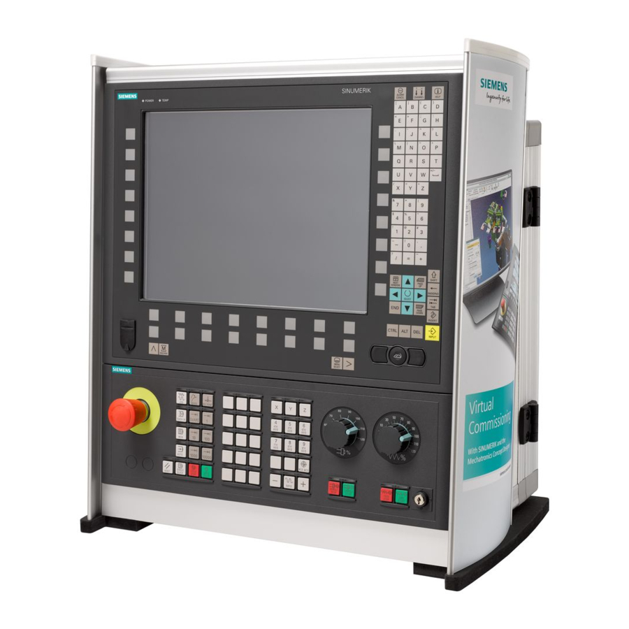
Introduction 1.2 Operator panel fronts Operator panel fronts 1.2.1 Overview Introduction The display (screen) and operation (e.g. hardkeys and softkeys) of the HMI sI user interface occurs via the panel front. In this example, the operator OP 010 panel front is used to illustrate the components that are available for operating the controller and machine tool. -
Page 13: Keys Of The Operator Panel
Introduction 1.2 Operator panel fronts Numerical key group Softkeys Control key group Hotkey group Cursor key group USB interface Menu select key Menu forward button Machine area button Menu back key References An exact description as well as a view of the other serviceable panel fronts may be found in /BH/, 840D sl / 840Di sl Operator Components Manual 1.2.2 Keys of the operator panel... - Page 14 Introduction 1.2 Operator panel fronts Function Cursor Input focus/cursor between different fields. Navigate rows or characters. Use the right cursor to open a directory or program in the editor. Use the left cursor to switch to a higher level in the directory tree. SELECT Choose one of a number of options presented.
-
Page 15: Machine Control Panels
1.3.1 Overview The machine tool can be equipped with a machine control panel by Siemens or with a specific machine control panel from the machine manufacturer. You use the machine control panel to initiate actions on the machine tool such as traversing an axis or starting the machining of a workpiece. - Page 16 Introduction 1.3 Machine control panels EMERGENCY STOP button Activate the button in situations where life is at risk. • there is the danger of a machine or workpiece being damaged. • All drives will be stopped with the greatest possible braking torque. Machine manufacturer For additional responses to pressing the Emergency Stop button, please refer to the machine manufacturer's instructions.
- Page 17 Introduction 1.3 Machine control panels Customer keys T1 to T15 Traversal axes with rapid traverse superposition and coordinate exchange Axis keys Selects an axis. Direction keys Select the traversing direction. RAPID Traverse axis in rapid traverse while pressing the direction key. WCS MCS Switches between the workpiece coordinate system (WCS = work) and machine coordinate system (MCS = machine).
-
Page 18: Operator Interface
Introduction 1.4 Operator interface Operator interface 1.4.1 Screen layout Overview Figure 1-3 User interface Active operating area and mode Alarm/message line Program name Channel state and program control Channel operational messages HMI sl Universal Operating Manual, 01/2008, 6FC5398-6AP10-2BA0... -
Page 19: Status Display
Introduction 1.4 Operator interface Axis position display in actual value window Display for active tool T • current feedrate F • active spindle with current status (S) • Operating window with program block display Display of active G functions, all G functions, H functions and input window for different functions (for example, skip blocks, program control) Dialog line to provide additional user notes Horizontal softkey bar... - Page 20 Introduction 1.4 Operator interface Status display of "Machine" operating area First line Display Description Active operating area "Machine" operating area With touch operation, you can change the operating area here. "Parameter" operating area "Program" operating area "Program manager" operating area "Diagnosis"...
- Page 21 Introduction 1.4 Operator interface Alarms and messages Alarm display The alarm numbers are displayed in white lettering on a red background. The associated alarm text is shown in red lettering. An arrow indicates that several alarms are active. An acknowledgment symbol indicates that the alarm can be acknowledged or canceled.
-
Page 22: Actual Value Window
Introduction 1.4 Operator interface Display Description Display of active program controls: PRT: no axis motion DRY: Dry run feedrate M01: programmed stop 1 M101: programmed step 2 (name varies) SB1: Single block, coarse (program stops only after blocks which perform a machine function) SB2: Data block (program stops after each block) SB3: Single block, fine (program also only stops after blocks which perform a machine function in cycles) - Page 23 Introduction 1.4 Operator interface Machine manufacturer Please refer to the machine manufacturer's specifications. Maximize display Press the ">>" and "Zoom act.val." softkeys. Overview of display Display Meaning Header columns WCS/MCS Display of axes in selected coordinate system. Item Position of displayed axes. Display of distance-to-go The distance-to-go for the current NC block is displayed while the program is running.
-
Page 24: T,F,S Window
Introduction 1.4 Operator interface 1.4.4 T,F,S window The most important data concerning the current tool, the feedrate (path feed or axis feed in JOG) and the spindle are displayed in the T, F, and S windows. Tool data Display Meaning Tool name Name of current tool Location... -
Page 25: Current Block Display
Introduction 1.4 Operator interface Display Meaning Icon Spindle status Spindle not enabled Spindle is turning clockwise Spindle is turning counterclockwise Spindle is stationary Override Display as a percentage Spindle utilization Display between 0 and 100% rate The upper limit value can be greater than 100% See machine manufacturer's specifications. -
Page 26: Operation Via Softkeys And Buttons
Introduction 1.4 Operator interface 1.4.6 Operation via softkeys and buttons Operating areas/operating modes The user interface consists of different windows featuring eight horizontal and eight vertical softkeys. You operate the softkeys with the keys next to the softkey bars. You can display a new window or execute functions using the softkeys. HMI sl is divided into six operating areas (machine, parameter, program, program manager, diagnosis, startup) and five operating modes or submodes (JOG, MDA, AUTO, TEACH In, REF POINT, REPOS). -
Page 27: Entering Or Selecting Parameters
Introduction 1.4 Operator interface Use the "<<" softkey to return to the previous vertical softkey bar. Use this softkey to close the open window. Use the "Cancel" softkey to exit a window without accepting the entered values and return to the next highest window. When you have entered all the necessary parameters in the parameter screen form correctly, you can close the window and save the parameters using the "Accept"... - Page 28 Introduction 1.4 Operator interface Selecting parameters Some parameters require you to select from a number of options in the input field. Fields of this type do not allow you to type in a value. The selection symbol is displayed in the tooltip: Associated selection fields There are selection fields for various parameters: ●...
- Page 29 Introduction 1.4 Operator interface Changing or calculating parameters If you only want to change individual characters in an input field rather than overwriting the entire entry, switch to insertion mode. In this mode, the pocket calculator is also active. You can use it during programming to calculate parameter values.
-
Page 30: Pocket Calculator
Introduction 1.4 Operator interface 1.4.8 Pocket calculator You can use the pocket calculator to quickly calculate parameter values during programming. If, for example, the diameter of a workpiece is only dimensioned indirectly in the workpiece drawing, i.e., the diameter must be derived from the sum of several other dimension specifications, you can calculate the diameter directly in the input field of this parameter. -
Page 31: Context Menu
Introduction 1.4 Operator interface Press the "=" softkey. - OR - Press the "Calculate" softkey. - OR - Press the "INPUT" key. The new value is calculated and displayed in the input field of the pocket calculator. Press the "Accept" softkey. The calculated value is accepted and displayed in the input field of the window. -
Page 32: Touch Operation
Introduction 1.4 Operator interface 1.4.10 Touch operation If you have an operator panel with a touch screen, you can perform the following functions with touch operation: Operating area switchover You can display the operating area menu by touching the display symbol for the active operating area in the status display. -
Page 33: Editing Asian Characters
Introduction 1.4 Operator interface Press the <INPUT> key. The user interface changes to the selected language. Note Changing the language directly on the input screens You can switch between the user interface languages available on the controller directly on the user interface by pressing the key combination <CTRL + L>. 1.4.12 Editing Asian characters You can edit Asian characters. - Page 34 Introduction 1.4 Operator interface Requirement The control has been set to Chinese or Korean. Procedure Editing characters Open the screen form and position the cursor on the entry field and press the <Alt +S> keys. The editor is displayed. Enter the desired phonetic notation. Click the "Cursor down"...
-
Page 35: Protection Levels
● Tool offsets ● Work offsets ● Setting data ● Program creation / program editing For additional information, please refer to the following documentation: HMI sl / SINUMERIK 840D sl Commissioning Manual Softkeys Startup operating area Protection levels End user... -
Page 36: Online Help In Hmi Sl
Introduction 1.4 Operator interface Startup operating area Protection levels End user (protection level 3) End user (protection level 3) 1.4.14 Online help in HMI sl A comprehensive context-sensitive online help is stored in the control system. ● A brief description is provided for each window and, if required, step-by-step instructions for the operating sequences. - Page 37 Introduction 1.4 Operator interface Press the "Table of contents" softkey. Depending on which technology you are using, the "HMI sl Milling", "HMI sl Turning" or "HMI sl Universal" Operating and Commissioning Manuals as well as the "Programming" Manual are displayed. Select the desired manual with the "Cursor down"...
- Page 38 Introduction 1.4 Operator interface Displaying alarm descriptions and machine data If messages or alarms are pending in the "Alarms", "Messages" or "Alarm Log" window, position the cursor at the appropriate display and press the <Help> or the <F12> key. The associated alarm description is displayed. If you are in the "Startup"...
-
Page 39: Setting Up The Machine
Setting up the machine Switching on and switching off Start-up When the control starts up, the main screen opens according to the operating mode specified by the machine manufacturer. In general, this is the main screen for the "REF POINT" submode. Machine manufacturer Please also refer to the machine manufacturer's instructions. -
Page 40: Approaching A Reference Point
Setting up the machine 2.2 Approaching a reference point Approaching a reference point 2.2.1 Referencing axes Your machine tool can be equipped with an absolute or incremental path measuring system. An incremental path measuring system must be calibrated after being switched on, but an absolute path measuring system does not. -
Page 41: User Agreement
Setting up the machine 2.2 Approaching a reference point Press the "+" or "-" key. The selected axis moves to the reference point. If you have pressed the wrong direction key, the action is not accepted and the axes do not move. A symbol is shown next to the axis if it has been referenced. -
Page 42: Modes Of Operation
Setting up the machine 2.3 Modes of operation Press the "+" or "-" key. The selected axis moves to the reference point and stops. The coordinate of the reference point is displayed. The axis is marked with Press the "User enable" softkey. The "User Acknowledge"... - Page 43 Setting up the machine 2.3 Modes of operation Select "JOG" Press the "JOG" key. "Ref Point" submode The "REF POINT" submode is used to synchronize the control and the machine. For this purpose, you approach the reference point in "JOG" mode. Selecting "REF POINT"...
- Page 44 Setting up the machine 2.3 Modes of operation "MDA" mode (Manual Data Automatic) In "MDA" mode, you can enter and execute G code commands non-modally to set up the machine or to perform a single action. Selecting "MDA" Press the "MDA" key. "AUTO"...
-
Page 45: Channel Switchover
Setting up the machine 2.3 Modes of operation 2.3.2 Channel switchover It is possible to switch between channels when several are in use. Since individual channels may be assigned to different mode groups, a channel switchover command is also an implicit mode switchover command. -
Page 46: Settings For The Machine
Setting up the machine 2.4 Settings for the machine Settings for the machine 2.4.1 Switching over the coordinate system (MCS/WCS) The coordinates in the actual value display are relative to either the machine coordinate system or the workpiece coordinate system. By default, the workpiece coordinate system is set as a reference for the actual value display. - Page 47 Setting up the machine 2.4 Settings for the machine Machine manufacturer Please also refer to the machine manufacturer's instructions. Proceed as follows Select "JOG" or "AUTO" mode in the "Machine" operating area. Press the menu forward key and the "Settings" softkey. A new vertical softkey bar appears.
-
Page 48: Setting The Work Offset
Setting up the machine 2.4 Settings for the machine 2.4.3 Setting the work offset You can enter a new position value in the actual value display for individual axes when a settable work offset is active. The difference between the position value in the machine coordinate system MCS and the new position value in the workpiece coordinate system WCS is saved permanently in the currently active work offset (e.g. - Page 49 Setting up the machine 2.4 Settings for the machine Resetting the actual value Press the "Delete active WO" softkey. The offset is deleted permanently. NOTICE Irreversible active work offset The current active work offset is irreversibly deleted by this action. Relative actual value Press the "REL actual values"...
-
Page 50: Work Offsets
Setting up the machine 2.5 Work offsets Work offsets 2.5.1 Overview - Work offsets Following reference point approach, the actual value display for the axis coordinates is based on the machine zero (M) of the machine coordinate system (MCS). The program for machining the workpiece, however, is based on the workpiece zero (W) of the workpiece coordinate system (WCS). -
Page 51: Display Active Zero Offset
Setting up the machine 2.5 Work offsets Coarse and fine offsets Every work offset (G54 to G57, G505 to G599) consists of a coarse offset and a fine offset. You can call the work offsets from any program (coarse and fine offsets are added together). You can save the workpiece zero, for example, in the coarse offset, and then store the offset that occurs when a new workpiece is clamped between the old and the new workpiece zero in the fine offset. -
Page 52: Displaying And Editing Base Zero Offset
Setting up the machine 2.5 Work offsets Procedure Select the "Parameter" operating area. Press the "Work offset" softkey. The "Work Offset - Active" window is opened. Note Further details on work offsets If you would like to see further details about the specified offsets or if you would like to change values for the rotation, scaling or mirroring, press the "Details"... -
Page 53: Displaying And Editing Settable Zero Offset
Setting up the machine 2.5 Work offsets Note Activate base offsets The offsets specified here are immediately active. 2.5.4 Displaying and editing settable zero offset All settable offsets, divided into coarse and fine offsets, are displayed in the "Work Offset - G54..G599"... -
Page 54: Displaying And Editing Details Of The Zero Offsets
Setting up the machine 2.5 Work offsets 2.5.5 Displaying and editing details of the zero offsets For each work offset, you can display and edit all data for all axes. You can also delete work offsets. For every axis, values for the following data will be displayed: ●... - Page 55 Setting up the machine 2.5 Work offsets Press the "Clear offset" softkey to reset all entered values. Press the "WO +" or "WO -" softkey to select the next or previous offset, respectively, within the selected area ("Active", "Base", "G54 to G599") without first having to switch to the overview window.
-
Page 56: Deleting A Work Offset
Setting up the machine 2.5 Work offsets 2.5.6 Deleting a work offset You have the option of deleting zero offsets. This resets the entered values. Proceed as follows Select the "Parameter" operating area. Press the "Work offset" softkey. Press the "Active", "Base" or "G54…G599" softkey. Press the "Details"... -
Page 57: Monitoring Axis And Spindle Data
Setting up the machine 2.6 Monitoring axis and spindle data Monitoring axis and spindle data 2.6.1 Specify working area limitations The "Working area limitation" function can be used to limit the range within which a tool can traverse in all channel axes. These commands allow you to set up protection zones in the working area which are out of bounds for tool movements. -
Page 58: Editing Spindle Data
Setting up the machine 2.6 Monitoring axis and spindle data 2.6.2 Editing spindle data The speed limits set for the spindles that must not be under- or overshot are displayed in the "Spindles" window. You can limit the spindle speeds in fields "Minimum" and "Maximum" within the limit values defined in the relevant machine data. -
Page 59: Manual Mode
Setting up the machine 2.7 Manual mode Manual mode 2.7.1 General Always use "JOG" mode when you want to set up the machine for the execution of a program or to carry out simple traversing movements on the machine: ● Synchronize the measuring system of the controller with the machine (reference point approach) ●... - Page 60 Setting up the machine 2.7 Manual mode Display Meaning Input of the tool (name or location number) You can select a tool from the tool list via the "Tool" softkey. Cutting edge number of the tool (1 - 9) Spindle Spindle selection, identification with spindle number Spindle M function Spindle off: Spindle is stopped...
-
Page 61: Selecting A Tool
Setting up the machine 2.7 Manual mode 2.7.2.2 Selecting a tool Procedure Select the "JOG" operating mode. Press the "T, S, M" softkey. Enter the name or the number of the tool T in the input field. - OR - Press the "Tool"... -
Page 62: Starting And Stopping A Spindle Manually
Setting up the machine 2.7 Manual mode 2.7.2.3 Starting and stopping a spindle manually Procedure Select the "JOG" operating mode. Press the "T, S, M" softkey. Select the desired spindle (e.g. S1) and enter the desired spindle speed (rpm) in the adjacent input field. The spindle remains stationary. -
Page 63: Position Spindle
Setting up the machine 2.7 Manual mode 2.7.2.4 Position spindle Procedure Select "JOG" mode. Press the "T, S, M" softkey. Select the "Stop Pos." setting in the "Spindle M function" field. The "Stop Pos." entry field appears. Enter the desired spindle stop position. The spindle position is specified in degrees. -
Page 64: Traversing Axes
Setting up the machine 2.7 Manual mode 2.7.3 Traversing axes You can traverse the axes in manual mode via the Increment or Axis keys or handwheels. During a traverse initiated from the keyboard, the selected axis moves at the programmed setup feedrate. - Page 65 Setting up the machine 2.7 Manual mode Note When the control is switched on, the axes can be traversed right up to the limits of the machine as the reference points have not yet been approached and the axes referenced. Emergency limit switches might be triggered as a result.
-
Page 66: Traversing Axes By A Variable Increment
Setting up the machine 2.7 Manual mode 2.7.3.2 Traversing axes by a variable increment Proceed as follows Select the "Machine" operating area. Press the "JOG" key. Press the "Settings" softkey. The "Settings for manual operation" window is opened. Enter the desired value for the "Variable increment" parameter. Example Enter 500 for a desired increment of 500 μm (0.5 mm). -
Page 67: Default Settings For Manual Mode
Setting up the machine 2.7 Manual mode Press the "Rapid traverse" softkey. The rapid traverse is displayed in field "F". Enter the target position or target angle for the axis or axes to be traversed. Press the "CYCLE START" key. The axis is traversed to the specified target position. -
Page 68: Handwheel Assignment
Setting up the machine 2.8 Handwheel assignment Handwheel assignment You can traverse the axes in the machine coordinate system (MCS) or in the workpiece coordinate system (WCS) via the handwheel. All axes are provided in the following order for handwheel assignment: ●... - Page 69 Setting up the machine 2.8 Handwheel assignment Press the "Back" softkey. The "Handwheel" window closes. Deactivate handwheel Place the cursor on the handwheel whose assignment you wish to cancel (e.g., no. 1). Press the softkey for the assigned axis again (e.g. "X"). - OR - To open the "Axis"...
-
Page 70: Mda
Setting up the machine 2.9 MDA In "MDA" mode (Manual Data Automatic mode), you can enter G-code commands block-by- block and immediately execute them for setting up the machine. You can load an MDA program straight from the Program Manager into the MDA buffer. You may also store programs which were rendered or changed in the MDA operating window into any directory of the Program Manager. -
Page 71: Saving An Mda Program
Setting up the machine 2.9 MDA 2.9.2 Saving an MDA program Proceed as follows Select the "Machine" operating area. Press the "MDA" key. The MDA editor opens. Create the MDA program by entering the G-code commands using the operator's keyboard. Press the "Store MDA"... -
Page 72: Executing An Mda Program
Setting up the machine 2.9 MDA 2.9.3 Executing an MDA program Proceed as follows Select the "Machine" operating area. Press the "MDA" key. The MDA editor opens. Input the desired G-code commands using the operator’s keyboard. Press the "CYCLE START" key. The control executes the input blocks. -
Page 73: Deleting An Mda Program
Setting up the machine 2.9 MDA 2.9.4 Deleting an MDA program Requirement The MDA editor contains a program that you created in the MDI window or loaded from the program manager. Procedure Press the "Delete MDI buffer" softkey. The program displayed in the program window is deleted. HMI sl Universal Operating Manual, 01/2008, 6FC5398-6AP10-2BA0... - Page 74 Setting up the machine 2.9 MDA HMI sl Universal Operating Manual, 01/2008, 6FC5398-6AP10-2BA0...
-
Page 75: Machine The Workpiece
Machine the workpiece Starting program execution 3.1.1 Starting and stopping machining During execution of a program, the workpiece is machined in accordance with the programming on the machine. After the program is started in automatic mode, workpiece machining is performed automatically. Requirements The following requirements must be met before executing a program: ●... - Page 76 Machine the workpiece 3.1 Starting program execution Note Starting the program in any operating area If the control is in "AUTO" mode, you can also start the selected program when you are in any operating area. Stopping machining Press the "CYCLE STOP" key. Machining stops immediately.
-
Page 77: Selecting A Program
Machine the workpiece 3.2 Program running-in 3.1.2 Selecting a program Proceed as follows Select the "Program manager" operating area. The directory overview is opened. Place the cursor on the directory containing the program that you want to select. Press the “INPUT” key - OR - Press the "Cursor right"... - Page 78 Machine the workpiece 3.2 Program running-in Move by single block In "Program control" you may select from among several types of block processing: SB mode Scope SB1 Single block, The machining stops after every machine block (except for cycles) coarse SB2 Data block The machining stops after every block, i.e.
-
Page 79: Display Current Program Block
Machine the workpiece 3.3 Display current program block Display current program block 3.3.1 Current block display The window of the current block display shows you the program blocks currently being executed. Display of current program The following information is displayed in the running program: ●... -
Page 80: Display Program Level
Machine the workpiece 3.3 Display current program block Machine manufacturer Please refer to the machine manufacturer's specifications. Procedure A program is selected for execution and has been opened in the "Machine" operating area. Press the "Basic blocks" softkey. The "Basic Blocks" window opens. Press the <SINGLE BLOCK>... -
Page 81: Correcting A Program
Machine the workpiece 3.4 Correcting a program Correcting a program As soon as a syntax error in the part program is detected by the controller, program execution is interrupted and the syntax error is displayed in the alarm line. Correction possibilities Depending on the state of the control system, you can make the following corrections using the Program editing function. -
Page 82: Repositioning Axes
Machine the workpiece 3.5 Repositioning axes Repositioning axes After a program interruption in automatic mode (e.g. after a tool breaks) you can move the tool away from the contour in manual mode. The coordinates of the interrupt position will be saved. The distances traversed in manual mode are displayed in the actual value window. -
Page 83: Starting Execution At A Specific Point
Machine the workpiece 3.6 Starting execution at a specific point Starting execution at a specific point 3.6.1 Use block search If you would only like to perform a certain section of a program on the machine, then you need not start the program from the beginning. You can also start the program from a specified program block. - Page 84 Machine the workpiece 3.6 Starting execution at a specific point Cascaded search You can start another search from the "Search target found" state. The cascading can be continued any number of times after every search target found. Note Another cascaded block search can be started from the stopped program execution only if the search target has been found.
-
Page 85: Continuing Program From Search Target
Machine the workpiece 3.6 Starting execution at a specific point 3.6.2 Continuing program from search target To continue the program at the desired position, press the "CYCLE START" key twice. ● The first CYCLE START outputs the auxiliary functions collected during the search. The program is then in the Stop state. -
Page 86: Defining An Interruption Point As Search Target
Machine the workpiece 3.6 Starting execution at a specific point 3.6.4 Defining an interruption point as search target Requirement A program was selected in "AUTO" mode and interrupted during execution through "CYCLE STOP" or "RESET". Procedure Press the "Block search" softkey. Press the "Interrupt point"... -
Page 87: Entering The Search Target Via Search Pointer
Machine the workpiece 3.6 Starting execution at a specific point 3.6.5 Entering the search target via search pointer Enter the program point which you would like to proceed to in the "Search Pointer" window. Requirement The program is selected and the controller is in Reset mode. Screen form Each line represents one program level. -
Page 88: Parameters For Block Search In The Search Pointer
Machine the workpiece 3.6 Starting execution at a specific point Note Interruption point You can load the interruption point in search pointer mode. 3.6.6 Parameters for block search in the search pointer Parameter Meaning Number of program level Program: The name of the main program is automatically entered Ext: File extension Pass counter... - Page 89 Machine manufacturer Please refer to the machine manufacturer's specifications. References For additional information, please refer to the following documentation: HMI sl / SINUMERIK 840D sl Commissioning Manual Procedure Select the "Machine" operating area. Press the "AUTO" key. Press the "Block search" and "Block search mode" softkeys.
-
Page 90: Controlling The Program Run
Machine the workpiece 3.7 Controlling the program run Controlling the program run 3.7.1 Program control You can change the program sequence in the "AUTO" and "MDA" modes. Abbreviation/program Scope control The program is started and executed with auxiliary function outputs and dwell times. In this mode, the axes are not traversed. -
Page 91: Skip Blocks
Machine the workpiece 3.7 Controlling the program run Display / response of active program controls: If a program control is activated, the abbreviation of the corresponding function appears in the status display as response. Proceed as follows Select the "Machine" operating area. Press the "AUTO"... - Page 92 Machine the workpiece 3.7 Controlling the program run Machine manufacturer Please also refer to the machine manufacturer's instructions. Skip levels, activate Check the corresponding checkbox in order to skip the required block level. Note The "Program control - skip blocks" window is only available when more than one skip level is set up.
-
Page 93: Overstore
Machine the workpiece 3.8 Overstore Overstore This function allows you to overstore technological parameters (for example, auxiliary functions, axis feed, spindle speed, programmable instructions, etc.) for a program run in the main memory of the NCK. When next started, the program will be executed as originally programmed. Requirement The program to be corrected is in the Stop or Reset mode. -
Page 94: Editing A Program
Machine the workpiece 3.9 Editing a program Deleting blocks Press the "Delete blocks" softkey to delete program blocks you have entered. Editing a program 3.9.1 Overview - Program editor With the editor, you are able to render, supplement, or change part programs. Note The maximum block length is 512 characters. -
Page 95: Searching In Programs
Machine the workpiece 3.9 Editing a program 3.9.2 Searching in programs You can use the search function to quickly arrive at points where you would like to make changes, e.g. in very large programs. Requirement The desired program is opened in the editor. Procedure Press the "Search"... -
Page 96: Replacing Program Text
Machine the workpiece 3.9 Editing a program 3.9.3 Replacing program text You can find and replace text in one step. Requirement The desired program is opened in the editor. Proceed as follows Press the "Search" softkey. A new vertical softkey bar appears. Press the "Find + replace"... -
Page 97: Copying/Pasting/Deleting Program Blocks
Machine the workpiece 3.9 Editing a program 3.9.4 Copying/pasting/deleting program blocks Requirement The program is opened in the editor. Procedure Press the "Mark" softkey. - OR - Press the "SELECT" key. Select the desired program blocks with the cursor or mouse. Press the "Copy"... -
Page 98: Renumbering A Program
Machine the workpiece 3.9 Editing a program 3.9.5 Renumbering a program You can modify the block numbering of programs opened in the editor at a later point in time. Requirement The program is opened in the editor. Procedure Press the ">>" softkey. A new vertical softkey bar appears. -
Page 99: Editor Settings
Machine the workpiece 3.9 Editing a program 3.9.6 Editor settings Enter the default settings in the "Settings" window that are to take effect automatically when the editor is opened. Presettings Settings Meaning Number Yes: A new block number will automatically be assigned after every line automatically change. - Page 100 Machine the workpiece 3.9 Editing a program Procedure Select the "Program" operating area You have activated the editor. Press the ">>" and "Settings" softkeys. The "Settings" window appears. Make the desired changes here and press the "OK" softkey to confirm your settings.
-
Page 101: Simulating Machining
Machine the workpiece 3.10 Simulating machining 3.10 Simulating machining 3.10.1 Overview During simulation, the current program is calculated in its entirety and the result displayed in graphic form. The result of programming is verified without traversing the machine axes. Incorrectly programmed machining steps are detected at an early stage and incorrect machining on the workpiece prevented. -
Page 102: Simulation Prior To Machining Of The Workpiece
Machine the workpiece 3.10 Simulating machining Views The following views are available for all three variants: ● Top view ● 3D view ● 4-window view ● Side view Status display The current axis coordinates, the override, the current tool with cutting edge, the current program block, the feedrate and the machining time are displayed. -
Page 103: Start Simulation
Machine the workpiece 3.10 Simulating machining 3.10.2.1 Start simulation Procedure Select the "Program manager" operating area. Select the desired storage location and position the cursor on the program to be simulated. Press the <INPUT> or <Cursor right> key. - OR - Double-click the program. -
Page 104: Starting Simultaneous Recording
Machine the workpiece 3.10 Simulating machining 3.10.3.1 Starting simultaneous recording Procedure Load a program in the "AUTO" mode. Press the "Prog. ctrl." softkey and activate the checkboxes "PRT no axis movement" and "DRY run feedrate". The program is executed without axis movement. The programmed feedrate is replaced by a dry run feedrate. -
Page 105: Different Views Of A Workpiece
Machine the workpiece 3.10 Simulating machining 3.10.5 Different views of a workpiece In the graphical display, you can choose between different views so that you constantly have the best view of the current workpiece machining, or in order to display details or the overall view of the finished workpiece. -
Page 106: View
Machine the workpiece 3.10 Simulating machining 3.10.5.2 3D view Start the simulation. Press the "3D view" softkey. Software option You require the option "3D simulation (finished part)" for the simulation. Changing the display You can increase or decrease the size of the simulation graphic, move it, turn it, or change the segment. -
Page 107: Side View
Machine the workpiece 3.10 Simulating machining 3.10.5.4 Side view Start the simulation. Press the "Additional views" and "Side view" softkeys. Changing the display You can increase or decrease the size of the simulation graphic and move it, as well as change the segment. -
Page 108: Editing The Simulation Display
Machine the workpiece 3.10 Simulating machining 3.10.7 Editing the simulation display 3.10.7.1 Blank display You can change the blank defined in the program. Procedure The simulation or the simultaneous recording is started. Press the ">>" and "Blank" softkeys. The "Blank Input" windows opens and displays the pre-assigned values. -
Page 109: Program Control During Simulation
Machine the workpiece 3.10 Simulating machining 3.10.8 Program control during simulation 3.10.8.1 Changing the feedrate You can change the feedrate at any time during the simulation. You can track the changes in the dialog line. Note If you are working with the "Simultaneous recording" function, the override rotary switch on the control panel is used. -
Page 110: Simulating The Program Block By Block
Machine the workpiece 3.10 Simulating machining 3.10.8.2 Simulating the program block by block You can control the program execution during simulation, i.e. execute a program block by block, as when executing a program. Procedure Simulation is started. Press the "Program control" and "Single block" softkeys. Press the "<<"... -
Page 111: Modifying And Adapting The Simulation Graphics
Machine the workpiece 3.10 Simulating machining 3.10.9 Modifying and adapting the simulation graphics 3.10.9.1 Enlarging or reducing the graphical representation Requirement The simulation or the simultaneous recording is started. Procedure Press the <+> and <-> keys if you want to enlarge or reduce the graphical representation now displayed. -
Page 112: Panning A Graphical Representation
Machine the workpiece 3.10 Simulating machining 3.10.9.2 Panning a graphical representation Requirement The simulation or the simultaneous recording is started. Procedure Press a cursor key if you want to move the graphic up, down, left, or right. 3.10.9.3 Rotating the graphical representation In the 3D view and in the 4-window view, you can rotate the workpiece to view it from all sides. -
Page 113: Modifying The Viewport
Machine the workpiece 3.10 Simulating machining 3.10.9.4 Modifying the viewport If you would like to move, enlarge or decrease the size of the segment of the graphical display, e.g. to view details or display the complete workpiece, use the magnifying glass. Using the magnifying glass, you can define your own segment and then increase or decrease its size. - Page 114 Machine the workpiece 3.10 Simulating machining Procedure Press the "Program control" and "Alarm" softkeys. The "Simulation Alarms" window is opened and a list of all pending alarms is displayed. Press the "Acknowledge alarm" softkey to reset the simulation alarms indicated by the Reset or Cancel symbol. The simulation can be continued.
-
Page 115: Display G And Auxiliary Functions
Machine the workpiece 3.11 Display G and auxiliary functions 3.11 Display G and auxiliary functions 3.11.1 Selected G functions 16 selected G groups are displayed in the "G Function" window. Within a G group, the G function currently active in the controller is displayed. Some G codes (e.g. - Page 116 Machine the workpiece 3.11 Display G and auxiliary functions Group Meaning G group 1 Modally active motion commands (e.g. G0, G1, G2, G3) G group 2 Non-modally active motion commands, dwell time (e.g. G4, G74, G75) G group 3 Programmable offsets, working area limitations and pole programming (e.g. TRANS, ROT, G25, G110) G group 6 Plane selection (e.g.
-
Page 117: All G Functions
Machine the workpiece 3.11 Display G and auxiliary functions References For more information about configuring the displayed G groups, refer to the following document: HMI sl / 840D sl Commissioning Manual 3.11.2 All G functions All G groups and their group numbers are listed in the "G Functions" window. Within a G group, only the G function currently active in the controller is displayed. -
Page 118: Auxiliary Functions
Machine the workpiece 3.11 Display G and auxiliary functions Procedure Select the "Machine" operating area. Press the "JOG", "AUTO", or "MDA" key. Press the ">>" and "All G functions" softkeys. The "G Functions" window is opened. 3.11.3 Auxiliary functions Auxiliary functions include M and H functions preprogrammed by the machine manufacturer, which transfer parameters to the PLC to trigger reactions defined by the manufacturer. - Page 119 Machine the workpiece 3.11 Display G and auxiliary functions Press the "H functions" softkey. The "Auxiliary Functions" window opens. Press the "H functions" softkey again to hide the window again. You can display status information for diagnosing synchronized actions in the "Synchronized Actions"...
-
Page 120: Displaying The Program Runtime And Counting Workpieces
Machine the workpiece 3.12 Displaying the program runtime and counting workpieces Procedure Select the "Machine" operating area. Press the "AUTO" key. Press the menu forward key and the "Synchron." softkey. The "Synchronized Actions" window appears. 3.12 Displaying the program runtime and counting workpieces To gain an overview of the program runtime and the number of machined workpieces, open the "Times, Counter"... - Page 121 Machine the workpiece 3.12 Displaying the program runtime and counting workpieces If you are executing the program from an external location, the program loading progress is displayed here. ● Influencing the time measurement The time measurement is started with the start of the program and ends with the end of the program (M30) or with an agreed M function.
-
Page 122: Setting For Automatic Mode
Machine the workpiece 3.13 Setting for automatic mode 3.13 Setting for automatic mode 3.13.1 Defining the dry run feedrate Before machining a workpiece, test the program without moving the machine axes. This allows for early detection of programming errors. For this test, you can use a dry run feedrate that you have defined. -
Page 123: User Data
User data Overview The defined user data may be displayed in lists. The following variables can be defined: ● Data parameters (R parameters) ● Global user data (GUD) is valid in all programs ● Local user data (LUD) is valid in one program ●... -
Page 124: R Parameters
User data 4.2 R parameters Searching for user data You may search for user data within the lists using any character string. Refer to the "Defining and activating user data" section to learn how to edit displayed user data. R parameters R parameters (arithmetic parameters) are channel-specific variables that you can use within a G code program. -
Page 125: Displaying Global User Data (Gud)
User data 4.3 Displaying global user data (GUD) Delete R variables Press the ">>" and "Delete area" softkeys. The "Delete R parameters" window appears. Enter the R parameter(s) whose channel-specific values you would like to delete and press the "OK" softkey. - OR - Press the "Delete all"... - Page 126 User data 4.3 Displaying global user data (GUD) GUDs are defined in files with the ending DEF. The following file names are reserved for this purpose: File name Description MGUD.DEF Definitions for global machine manufacturer data UGUD.DEF Definitions for global user data GUD4.DEF User-definable data GUD8.DEF, GUD9.DEF...
-
Page 127: Displaying Channel Guds
User data 4.4 Displaying channel GUDs Displaying channel GUDs Channel-specific user data Like the GUDs, channel-specific user data are applicable in all programs for each channel. However, unlike GUDs, they have specific values. Definition A channel-specific GUD variable is defined with the following: ●... -
Page 128: Displaying Local User Data (Lud)
User data 4.5 Displaying local user data (LUD) Press the "Continue" softkey and the "GUD7" to "GUD9" softkeys if you want to display GUD 7 to GUD 9 of the channel-specific user data. Displaying local user data (LUD) Local user data LUDs are only valid in the program or subroutine in which they were defined. -
Page 129: Displaying Program User Data (Pud)
User data 4.6 Displaying program user data (PUD) Displaying program user data (PUD) Program-global user data PUDs are global part program variables (Program User Data). PUDs are valid in all main programs and subroutines, where they can also be written and read. Proceed as follows Select the "Parameter"... -
Page 130: Defining And Activating User Data
User data 4.8 Defining and activating user data Defining and activating user data By editing a DEF/MAC file, you can alter or delete existing definition/macro files or add new ones. Proceed as follows Select the "Startup" operating area. Press the "System data" softkey. In the data tree, select the "NC data"... - Page 131 User data 4.8 Defining and activating user data Activating user data Press the "Activate" softkey. A prompt is displayed. Select whether the current values in the definition files should be retained - OR - Select whether the current values in the definition files should be deleted.
- Page 132 User data 4.8 Defining and activating user data HMI sl Universal Operating Manual, 01/2008, 6FC5398-6AP10-2BA0...
-
Page 133: Teaching In A Program
Teaching in a program Overview The "Teach in" function can be used to edit programs in the "AUTO" and "MDA" modes. You can create and modify simple traversing blocks. You traverse the axes manually to specific positions in order to implement simple machining sequences and make them reproducible. -
Page 134: Inserting A Block
Teaching in a program 5.3 Inserting a block Note All defined axes are "taught in" in the first teach-in block. In all additional teach-in blocks, only axes modified by axis traversing or manual input are "taught in". If you exit teach-in mode, this sequence begins again. Operating mode or operating area switchover If you switch to another operating mode or operating area in teach-in mode, the position changes will be canceled and teach-in mode will be cleared. -
Page 135: Teach-In Via Windows
Teaching in a program 5.3 Inserting a block Press the "Teach position" softkey. A new program block with the current actual position values will be created. 5.3.1 Teach-in via Windows 5.3.1.1 General information The cursor must be positioned on an empty line. The windows for pasting program blocks contain input and output fields for the actual values in the WCS. -
Page 136: Teach In Rapid Traverse G0
Teaching in a program 5.3 Inserting a block Press the softkeys "Rap. tra. G0", "Straight line G1", or Circ. interm. pos. CIP" and "Circ. end pos. CIP". The relevant windows with the input fields are displayed. Traverse the axes to the relevant position. Press the "Accept"... -
Page 137: Teaching In Circle Intermediate And Circle End Point Cip
Teaching in a program 5.3 Inserting a block 5.3.1.4 Teaching in circle intermediate and circle end point CIP Enter the intermediate and end positions for the circle interpolation CIP. You teach-in each of these separately in a separate block. The order in which you program these two points is not specified. - Page 138 Teaching in a program 5.3 Inserting a block Procedure Select the "Machine" operating area. Press the "AUTO" or "MDA" key. Press the "TEACH IN" key. Press the "Teach prog." softkey. Press the ">>" and "ASPLINE" softkeys. The "Akima-spline" window opens with the input fields. Traverse the axes to the required position and if necessary, set the transition type for the starting point and end point.
-
Page 139: Input Parameters For Teach-In Blocks
Teaching in a program 5.3 Inserting a block 5.3.2 Input parameters for teach-in blocks Parameters for teach-in of position and teach-in of G0, G1, and circle end position CIP Parameter Description Approach position in X direction Approach position in Y direction Approach position in Z direction Feedrate (mm/r;... -
Page 140: Editing A Block
Teaching in a program 5.4 Editing a block Transition behavior at the beginning and end of the spline curve The following motion parameters are offered: Parameter Description Start BAUTO Automatic calculation BNAT Curvature is zero or natural BTAN Tangential EAUTO Automatic calculation ENAT Curvature is zero or natural... - Page 141 Teaching in a program 5.4 Editing a block Proceed as follows Select the "Machine" operating area. Press the "AUTO" or "MDA" key. Press the "TEACH IN" key. Press the "Teach prog." softkey. Click the program block to be edited. Press the relevant softkey "Teach position, "Rap. tra. G0", "Straight line G1", or "Circ.
-
Page 142: Selecting A Block
Teaching in a program 5.5 Selecting a block Selecting a block You have the option of setting the interrupt pointer to the current cursor position. The next time the program is started, processing will resume from this point. With teach-in, you can also change program areas that have already been executed. This automatically disables program processing. -
Page 143: Deleting A Block
Teaching in a program 5.6 Deleting a block Deleting a block You have the option of deleting a program block entirely. Requirement "AUTO" mode: The program to be processed is selected. Proceed as follows Select the "Machine" operating area. Press the "AUTO" or "MDA" key. Press the "TEACH IN"... -
Page 144: Settings For Teach-In
Teaching in a program 5.7 Settings for teach-in Settings for teach-in In the "Settings" window, you define which axes are to be included in the teach-in block and whether motion-type and continuous-path mode parameters are to be provided. Proceed as follows Select the "Machine"... -
Page 145: Tool Management
Tool management Lists for the tool management All tools and also all magazine locations that have been created or configured in the NC are displayed in the lists in the Tool area. All lists display the same tools in the same order. When switching between the lists, the cursor remains on the same tool in the same screen segment. -
Page 146: Magazine Management
Tool management 6.2 Magazine management Magazine management Depending on the configuration, the tool lists support a magazine management. Magazine management functions ● Press the "Magazine" horizontal softkey to obtain a list that displays tools with magazine- related data. ● The Magazine / Magazine location column is displayed in the lists. ●... -
Page 147: Tool Types
Tool management 6.3 Tool types Tool types A number of tool types are available when you create a new tool. The tool type determines which geometry data are required and how they will be computed. Possible tool types Figure 6-1 Example of Favorites list Figure 6-2 Available tools in the "New tool - milling cutter"... - Page 148 Tool management 6.3 Tool types Figure 6-3 Available tools in the "New tool - drill" window Figure 6-4 Available tools in the "New tool - special tools" window HMI sl Universal Operating Manual, 01/2008, 6FC5398-6AP10-2BA0...
-
Page 149: Tool Dimensioning
Tool management 6.4 Tool dimensioning Tool dimensioning This section provides an overview of the dimensioning of tools. Tool types Figure 6-5 End mill (Type 120) Figure 6-6 Face mill (Type 140) HMI sl Universal Operating Manual, 01/2008, 6FC5398-6AP10-2BA0... - Page 150 Tool management 6.4 Tool dimensioning Figure 6-7 Angle head cutter (Type 130) Figure 6-8 Drill (Type 200) HMI sl Universal Operating Manual, 01/2008, 6FC5398-6AP10-2BA0...
- Page 151 Tool management 6.4 Tool dimensioning Figure 6-9 Tap (Type 240) HMI sl Universal Operating Manual, 01/2008, 6FC5398-6AP10-2BA0...
- Page 152 Tool management 6.4 Tool dimensioning Figure 6-10 3D tool with an example of a cylindrical die-sinking cutter (Type 110) Figure 6-11 3D tool type with an example of a ballhead cutter (Type 111) HMI sl Universal Operating Manual, 01/2008, 6FC5398-6AP10-2BA0...
- Page 153 Tool management 6.4 Tool dimensioning Figure 6-12 3D tool with an example of an end mill with corner rounding (Type 121) Figure 6-13 3D tool type with an example of a bevel cutter (Type 155) HMI sl Universal Operating Manual, 01/2008, 6FC5398-6AP10-2BA0...
- Page 154 Tool management 6.4 Tool dimensioning Figure 6-14 3D tool with an example of a bevel cutter with corner rounding (Type 156) Figure 6-15 3D tool with an example of a tapered die-sinking cutter (Type 157) HMI sl Universal Operating Manual, 01/2008, 6FC5398-6AP10-2BA0...
- Page 155 Tool management 6.4 Tool dimensioning Figure 6-16 3D probe Machine manufacturer The tool length is measured to the center of the ball (length m) or to the ball circumference (length u). Please refer to the machine manufacturer's specifications. Note A 3D probe must be calibrated before use. HMI sl Universal Operating Manual, 01/2008, 6FC5398-6AP10-2BA0...
-
Page 156: Tool List
Tool management 6.5 Tool list Tool list All parameters and functions that are required to create and set up the tools are displayed in the tool list. Each tool is uniquely identified by the tool identifier and the replacement tool number. Tool parameters Column heading Meaning... - Page 157 Tool management 6.5 Tool list Machine manufacturer Please refer to the machine manufacturer's specifications. Icons in the tool list Icon/ Meaning Designation Tool type Red "X" The tool is disabled. Yellow triangle pointing The prewarning limit has been reached. downward Yellow triangle pointing The tool is in a special state.
-
Page 158: Creating A New Tool
Tool management 6.5 Tool list Tool type Additional parameters 140 Face milling External radius Tool angle 155 Bevel cutter Taper angle 156 Bevel cutter with corner Corner radius rounding Taper angle 157 Conical die-milling cutter Taper angle You can use the configuration file to specify the data to be displayed for specific tool types in the "Additional Data"... - Page 159 Tool management 6.5 Tool list Procedure Select the "Parameter" operating area. Press the "Tool list" softkey. Place the cursor in the tool list at the position where the new tool should be stored. For this, you can select an empty magazine location or the NC tool memory outside of the magazine.
-
Page 160: Managing Several Cutting Edges
● Size of tool References: For a description of configuration options, refer to the /IHsl/, HMI sl / SINUMERIK 840D sl Commissioning Manual 6.5.2 Managing several cutting edges In the case of tools with more than one cutting edge, a separate set of offset data is assigned to each cutting edge. -
Page 161: Deleting A Tool
Tool management 6.5 Tool list Repeat this process if you wish to create more tool edge offset data. Position the cursor on the cutting edge that you want to delete and press the "Delete cutting edge" softkey. The data set is deleted from the list. The first tool cutting edge cannot be deleted. -
Page 162: Loading And Unloading Tools
Tool management 6.5 Tool list 6.5.4 Loading and unloading tools You can load and unload tools to and from a magazine via the tool list. When a tool is loaded, it is taken to a magazine location. When it is unloaded, it is removed from the magazine and stored in the tool list. - Page 163 Tool management 6.5 Tool list Several magazines If you have configured several magazines, the "Load to ..." window appears after pressing the "Load" softkey. If you do not want to use the suggested empty location, then enter your desired magazine and magazine location.
-
Page 164: Selecting A Magazine
Tool management 6.5 Tool list 6.5.5 Selecting a magazine You can directly select the buffer memory, the magazine, or the NC memory. Procedure Select the "Parameter" operating area. Press the "Tool list" softkey. Press the "Magazine selection" softkey. If there is only one magazine, you will move from one area to the next (i.e. - Page 165 The magazine selection behavior with multiple magazines can be configured in different ways. Machine manufacturer Please refer to the machine manufacturer's specifications. References For a description of configuration options, refer to the HMI sl / SINUMERIK 840D sl Commissioning Manual HMI sl Universal Operating Manual, 01/2008, 6FC5398-6AP10-2BA0...
-
Page 166: Tool Wear
Tool management 6.6 Tool wear Tool wear All parameters and functions that are required during operation are contained in the tool wear list. Tools that are in use for long periods are subject to wear. You can measure this wear and enter it in the tool wear list. - Page 167 Tool management 6.6 Tool wear Column heading Meaning Tool life Tool life Workpiece count Number of workpieces Wear * Tool wear *Parameter depends on selection in TC The tool is disabled when the checkbox is selected. Icons in the wear list Icon/ Meaning Designation...
-
Page 168: Reactivating A Tool
Machine manufacturer Please refer to the machine manufacturer's specifications. References HMI sl / SINUMERIK 840D sl Commissioning Manual Multiple load points If you have configured several loading points for a magazine, then the "Loading Point Selection" window appears after pressing the "Load" softkey. -
Page 169: Tool Data Oem
In the OEM tool list, you can customize a list according to your specific needs. References: For more information, see the following references: /IHsl/, HMI sl / SINUMERIK 840D sl Commissioning Manual Procedure Select the "Parameter" operating area. Press the "OEM Tool" soft key. -
Page 170: Magazine
Tool management 6.8 Magazine Magazine Tools are displayed with their magazine-related data in the magazine list. Here, you can take specific actions relating to the magazines and the magazine locations. Individual magazine locations can be location-coded or disabled for existing tools. Tool parameters Column heading Meaning... - Page 171 Tool management 6.8 Magazine Magazine list icons Icon/ Meaning Designation Tool type Red "X" The tool is disabled. Yellow triangle pointing The prewarning limit has been reached. downward Yellow triangle pointing The tool is in a special state. upward Place the cursor on the marked tool. A tooltip provides a short description.
-
Page 172: Position Magazine
Tool management 6.8 Magazine 6.8.1 Position magazine You can position magazine locations directly on the loading point. Procedure Select the "Parameter" operating area. Press the "Magazine” softkey. Place the cursor on the magazine location that you want to position onto the load point. Press the "Position magazine"... - Page 173 Tool management 6.8 Magazine Procedure Select the "Parameter" operating area. Press the "Magazine” softkey. Position the cursor on the tool that you wish to relocate to a different magazine location. Press the "Relocate" softkey. The "... relocate from location ... to ..." window appears on the screen. The "...
-
Page 174: Sorting Tool Management Lists
Tool management 6.9 Sorting tool management lists Sorting tool management lists When you are working with many tools, with large magazines or several magazines, it is useful to display the tools sorted according to different criteria. Then you will be able to find a specific tool more quickly in the lists. -
Page 175: Program Management
Program management Overview You can access these programs at any time via the Program Manager for execution, editing, copying, or renaming. Programs that you no longer require can be deleted to release their storage space. NOTICE Execution from USB FlashDrive Direct execution from a USB FlashDrive is not recommended. - Page 176 Program management 7.1 Overview Data exchange with other workstations You have the following options for exchanging programs and data with other workstations: ● USB drives (e.g. USB FlashDrive) ● Network drives Choosing storage locations In the horizontal softkey bar, you can select the storage location that contains the directories and programs that you want to display.
-
Page 177: Nc Memory
Program management 7.1 Overview Magazine assignment: TMA Zero points: UFR R parameters: RPA Global user data/definitions: GUD Setting data: SEA Protection zones: PRO Sag: CEC ● Size (in bytes) ● Date/time (of creation or last change) 7.1.1 NC memory The complete NC working memory is displayed along with all tools and the main programs and subroutines. -
Page 178: Usb Drives
Program management 7.1 Overview Procedure Select the "Program manager" operating area. Press the "Local drive" software key. 7.1.3 USB drives USB drives enable you to exchange data. For example, you can copy to the NC and execute programs that were created externally. NOTICE Execution from USB FlashDrive Direct execution from the USB FlashDrive is not recommended. -
Page 179: Opening And Closing A Program
Program management 7.2 Opening and closing a program Opening and closing a program To view a program in more detail or modify it, open the program in the editor. With programs that are in the NCK memory, navigation is already possible when opening. The program blocks can only be edited when the program has been opened completely. - Page 180 Program management 7.2 Opening and closing a program Closing the program Press the ">>" and "Exit" softkeys to close the program and editor again. - OR - If you are at the start of the first line of the program, press the "Cursor left" key to close the program and the editor.
-
Page 181: Executing A Program
Program management 7.3 Executing a program Executing a program When you select a program for execution, the controller automatically switches to the "Machine" operating area. Program selection Select the workpieces (WPD), main programs (MPF) or subprograms (SPF) by placing the cursor on the desired program or workpiece. -
Page 182: Creating A Directory/Program/Joblist/Program List
Program management 7.4 Creating a directory/program/joblist/program list If the selected program is already opened in the "Program" operating area, Press the "Execute NC" softkey. Press the "CYCLE START" key. Execution of the workpiece is started. Note Only workpieces/programs located in the NCK memory can be selected for execution. Creating a directory/program/joblist/program list 7.4.1 Creating a new directory... -
Page 183: Creating A New Workpiece
Program management 7.4 Creating a directory/program/joblist/program list Procedure Select the "Program manager" operating area. Select your chosen storage medium, i.e. a local or USB drive. If you want to create a new directory in the local network, place the cursor on the topmost folder and press the "New" and "Directory" softkeys. -
Page 184: Creating A New G Code Program
Program management 7.4 Creating a directory/program/joblist/program list Enter the desired workpiece name, select a template, if necessary, and press the "OK" softkey. The name can contain up to 28 characters (name + dot. + 3-character extension). You can use any letters (except umlauts), digits or the underscore symbol (_). -
Page 185: Storing Any New File
Program management 7.4 Creating a directory/program/joblist/program list Enter the desired program name and press the "OK" softkey. The program name can contain up to 28 characters (name + dot. + 3- character extension). You can use all letters (except accented characters), digits and underscores (_). -
Page 186: Creating A Joblist
Program management 7.4 Creating a directory/program/joblist/program list Enter a name and file format for the file to be created (e.g. My_Text.txt). The name can contain up to 28 characters (name + dot. + 3-character extension). You can use any letters (except umlauts), digits or the underscore symbol (_). -
Page 187: Creating A Program List
Program management 7.4 Creating a directory/program/joblist/program list Template You can select a template from Siemens or the machine manufacturer when creating a new job list. Executing a workpiece If the "Select" softkey is selected for a workpiece, the syntax of the associated job list is checked and then executed. - Page 188 Program management 7.4 Creating a directory/program/joblist/program list Procedure Select the "Program manager" operating area. Press the menu forward key and the "Program list" softkey. The "Program List" window appears. Place the cursor in the desired line (program number). Press the "Select program" softkey. The "Programs"...
-
Page 189: Creating Templates
Program management 7.5 Creating templates Creating templates You can store your own templates to be used for creating part programs and workpieces. These templates provide the basic framework for further editing. You can use them for any part programs or workpieces you have created. Storage location for templates The templates used to create part programs or workpieces are stored in the following directories:... -
Page 190: Displaying The Program In The Preview
Program management 7.6 Displaying the program in the Preview. Displaying the program in the Preview. You can show the content on a program in a preview before you start editing. Procedure Select the "Program manager" operating area. Select a storage location and place the cursor on the relevant program. - Page 191 Program management 7.7 Selecting several directories/programs Procedure Select the "Program manager" operating area. Choose the desired storage location and position the cursor on the file or directory from which you would like your selection to start. Press the "Mark" softkey. The softkey is active.
-
Page 192: Copying And Pasting A Directory/Program
Program management 7.8 Copying and pasting a directory/program Selecting with the mouse Key combination Meaning Left mouse Click on element: The element is selected. A previously existing selection is canceled. Left mouse + Expand selection consecutively up to the next click. pressed Left mouse + Expand selection to individual elements by clicking. - Page 193 Program management 7.8 Copying and pasting a directory/program If the files MYPROGRAM.MPF, MYPROGRAM__1.MPF, and MYPROGRAM__3.MPF already exist in a directory, MYPROGRAM__2.MPF is created as the next copy of MYPROGRAM.MPF. Procedure Select the "Program manager" operating area. Choose the desired storage location and position the cursor on the file or directory which you would like to copy.
-
Page 194: Deleting A Directory/Program
Program management 7.9 Deleting a directory/program Note Copying files in the same directory You cannot copy files to the same directory. You must copy the file under a new name. Deleting a directory/program Delete programs or directories from time to time that you are no longer using to maintain a clearer overview of your data management. -
Page 195: Changing File And Directory Properties
Program management 7.10 Changing file and directory properties 7.10 Changing file and directory properties Information on directories and files can be displayed in the "Properties for ..." window. Information on the creation date is displayed near the file's path and name. You can change names. - Page 196 Program management 7.11 Backing up data You can display the contents of the selected files (XML, ini, hsp, syf files, programs) in a preview. You can display information about the file, such as path, name, date of creation and change, in a Properties window.
- Page 197 Program management 7.11 Backing up data Procedure Select the "Startup" operating area. Press the "System data" softkey. The data tree opens. In the data tree, select the required files from which you want to generate an archive. - OR - If you want to back up several files or directories, press the "Select"...
-
Page 198: Reading In An Archive
Program management 7.11 Backing up data 7.11.2 Reading in an archive If you want to read in a specific archive, you can select this directly from the data tree. Procedure Select the "Startup" operating area. Press the "System data" softkey. Below the "Archive"... -
Page 199: Extcall
Program management 7.12 EXTCALL 7.12 EXTCALL The EXTCALL command can be used to access files on a local drive, USB data carriers or network drives from a part program. The programmer can set the source directory with the setting data SD42700 EXT_PROG_PATH and then specify the file name of the subprogram to be loaded with the EXTCALL command. - Page 200 Program management 7.12 EXTCALL The HMI user memory is subdivided into part programs (mpf.dir), subprograms (spf.dir) and workpieces (wks.dir) with the respective workpiece directories (.wpd). – SD42700 is empty: EXTCALL "TEST.MPF" The same search sequence is used on the CompactFlash card as in the NCK part program memory.
-
Page 201: Ht 8
HT 8 HT 8 overview The mobile SINUMERIK HT 8 handheld terminal combines the functions of an operator panel and a machine control panel. It is therefore suitable for visualization, operation, teach in, and programming at the machine. Customer keys (user-defined) Traversing keys User menu key Handwheel (optional) - Page 202 References For more information about connection and startup of the HT 8, see the following references: CNC Commissioning: SINUMERIK 840D sl, Operator Components and Networking Customer keys The four customer keys are freely assignable and can be set up customer-specifically by the machine manufacturer.
- Page 203 Handwheel The HT 8 is available with a hand wheel. References For information about connecting the hand wheel, refer to: CNC Commissioning: SINUMERIK 840D sl, Operator Components and Networking See also Channel switchover (Page 45) HMI sl Universal Operating Manual, 01/2008, 6FC5398-6AP10-2BA0...
-
Page 204: Traversing Keys
HT 8 8.2 Traversing keys Traversing keys The traversing keys are not labeled. However, you can display a label for the keys in place of the vertical softkey bar. Labeling of the traversing keys is displayed for up to six axes on the touch panel by default. Machine manufacturer Please refer to the machine manufacturer's specifications. -
Page 205: Machine Control Panel Menu
HT 8 8.3 Machine control panel menu Machine control panel menu Here you select keys from the machine control panel which are reproduced by the software by touch operation of the relevant softkeys. See chapter "Controls on the machine control panel" for a description of the individual keys. Note PLC interface signals that are triggered via the softkeys of the machine control panel menus are edge triggered. -
Page 206: Virtual Keyboard
HT 8 8.4 Virtual keyboard Softkeys on the machine control panel menu Available softkeys: "Machine" softkey Select the "Machine" operating area "[VAR]" softkey Select the axis feedrate in the variable increment "1… n CHANNEL" Change the channel softkey "Single Block" Switch single block execution on/off softkey "WCS MCS"... - Page 207 HT 8 8.4 Virtual keyboard Positioning of the virtual keyboard You can position the virtual keyboard anywhere in the window by pressing the empty bar next to the "Close window" icon with your finger or a stylus and moving it back and forth. Special keys on the virtual keyboard Num: Reduces the virtual keyboard to the number block.
-
Page 208: Calibrating The Touch Panel
HT 8 8.5 Calibrating the touch panel Calibrating the touch panel It is necessary to calibrate the touch panel upon first connection to the controller. Note Recalibration If the operation is not exact, then redo the calibration. Procedure Press the "Back" key and the "MENU SELECT" key at the same time to start the TCU service screen. -
Page 209: Alarm, Error, And System Messages
Alarm, error, and system messages Displaying alarms If faulty conditions are recognized in the operation of the machine, then an alarm will be generated and, if necessary, the machining will be interrupted. The error text that is displayed together with the alarm number gives you more detailed information on the error cause. - Page 210 Alarm, error, and system messages 9.1 Displaying alarms Select the "Diagnostics" operating area. Press the "Alarm list” softkey. The "Alarms" window appears. Position the cursor on an alarm. Press the key that is specified as acknowledgement symbol to delete the alarm. - OR - Press the "Delete HMI alarm"...
-
Page 211: Displaying Plc And Nc Variables
Alarm, error, and system messages 9.2 Displaying PLC and NC variables Displaying PLC and NC variables The "PLC/NC Status" window supports the observation and modification of PLC memory locations and NC system variables. You can also modify PLC memory locations. You receive information in the list on operands, with their format and status value. - Page 212 Alarm, error, and system messages 9.2 Displaying PLC and NC variables Changing and deleting values Select the "Diagnostics" operating area. Press the "Variab. view" softkey. The "Variables" window appears. Position the cursor in the "Operand" column and enter the required variable.
-
Page 213: Displaying An Alarm Log
Alarm, error, and system messages 9.3 Displaying an alarm log Displaying an alarm log A list of all the alarms and messages that have occurred so far are listed in the "Alarm Log" window. Up to 500 administered, incoming and outgoing events are displayed in chronological order. Machine manufacturer Please refer to the machine manufacturer's specifications. -
Page 214: Displaying Messages
Alarm, error, and system messages 9.4 Displaying messages Displaying messages PLC and part program messages may be issued during machining. These message will not interrupt the program execution. Messages provide information with regard to a certain behavior of the cycles and with regard to the progress of machining and are usually kept beyond a machining step or until the end of the cycle. -
Page 215: Displaying Version Data
Alarm, error, and system messages 9.5 Displaying version data Displaying version data All system software components are provided with their corresponding version data in the "Version Data" window. You may save the version data. Version displays saved as text files can be further processed as required or sent to the hotline in the event of an error. -
Page 216: Creating Screenshots
Specifying the storage location The storage location of the screenshots is defined in the "systemconfiguration.ini" file. The file is on the CF card in the following directory: Siemens/sinumerik/hmi/cfg. To change the storage location, copy the "systemconfiguration.ini" file to the "oem" or "user"... -
Page 217: Appendix
This document will be continuously improved with regard to its quality and ease of use. Please help us with this task by sending your comments and suggestions for improvement via e-mail or fax to: E-mail: mailto:docu.motioncontrol@siemens.com Fax: +49 9131 - 98 63315 Please use the fax form on the back of this page. - Page 218 Appendix A.1 Feedback on the documentation HMI sl Universal Operating Manual, 01/2008, 6FC5398-6AP10-2BA0...
-
Page 219: Overview
Appendix A.2 Overview Overview HMI sl Universal Operating Manual, 01/2008, 6FC5398-6AP10-2BA0... - Page 220 Appendix A.2 Overview HMI sl Universal Operating Manual, 01/2008, 6FC5398-6AP10-2BA0...
-
Page 221: Index
Index Continuous-path mode, 139 Coordinate system Switching over, 46 Copying Actual-value display, 22 Directory, 192 Alarm log Program, 192 Displaying, 213 Creating Alarms, 209 Any file, 185 Any file Directory, 182 Create, 185 G Code program, 184 Archive Job list, 186 Generate, 195, 197 Program list, 187 Reading in, 198... - Page 222 Index Machining Canceling, 76 Feed data Starting, 75 Actual value window, 24 Stopping, 75 Magazine, 170 Positioning, 172 Selecting, 164, 165 G Code program Magazine management, 146 Creating, 184 Manual mode, 59 G functions Positioning axes, 66 Display all G groups, 117 Settings, 67 G Functions Spindle, 62...
- Page 223 Index Program, 192 Pitch, 156 R parameters, 124 PLC status, 211 Reference point approach, 40 Pocket calculator, 30 Replacement tool number, 156 Preview Repositioning, 82 Program, 190 Program Closing, 179 Copying, 192 Deleting, 194 SB1, 78 Executing, 181 SB2, 78 Opening, 179 SB3, 78 Pasting, 192...
- Page 224 Index Coordinate system, 46 Channel GUD, 127 Unit of measurement, 46 Definition, 130 Synchronized actions Global GUD, 125 Displaying status, 119 Local LUD, 128 Program PUD, 129 R parameters, 124 Search, 129 User variables Teach-in, 133 Activate, 130 Changing blocks, 140 Global GUD, 130 Circle intermediate position CIP, 137 Deleting blocks, 143...