Table of Contents
Advertisement
SPLIT-TYPE AIR CONDITIONERS
SERVICE MANUAL
Wireless type
Models
MS-18RV -
MS-24RV -
MS-30RV -
MS-18RV -
E1
MS-24RV -
E1
· MU-18RV -
( WH )
E1
· MU-24RV -
( WH )
E1
· MU-30RV -
( WH )
E1
CONTENTS
1. TECHNICAL CHANGES ····································2
2. PART NAMES AND FUNCTIONS······················3
3. SPECIFICATION·················································6
4. NOISE CRITERIA CURVES ·······························8
5. OUTLINES AND DIMENSIONS ·······················10
6. WIRING DIAGRAM ··········································13
7. REFRIGERANT SYSTEM DIAGRAM ··············17
8. PERFORMANCE CURVES ······························20
9. MICROPROCESSOR CONTROL ····················34
10. SERVICE FUNCTIONS·····································45
11. TROUBLESHOOTING ······································47
12. DISASSEMBLY INSTRUCTIONS·····················61
13. PARTS LIST······················································69
14. OPTIONAL PARTS ······················BACK COVER
No. OB271
E1
E1
E1
Advertisement
Table of Contents

Related Manuals for Mitsubishi Electric MS-18RV-E1


Summary of Contents for Mitsubishi Electric MS-18RV-E1
-
Page 1: Table Of Contents
SPLIT-TYPE AIR CONDITIONERS No. OB271 SERVICE MANUAL Wireless type Models MS-18RV - · MU-18RV - ( WH ) MS-24RV - · MU-24RV - ( WH ) MS-30RV - · MU-30RV - ( WH ) CONTENTS 1. TECHNICAL CHANGES ····································2 2. PART NAMES AND FUNCTIONS······················3 3. -
Page 2: Technical Changes
TECHNICAL CHANGES MS-18NV - MS-18RV - MS-24NV - MS-24RV - 1. Remote controller has been changed. • SLEEP MODE function has removed. • ECONO COOL operation has added. • SWING button is removed, but SWING MODE function is available by VANE CONTROL button. MS-30RV - New model MU-18NV -... -
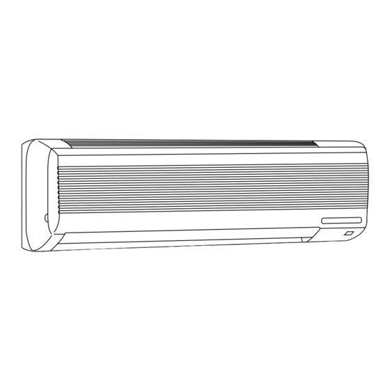
Page 3: Part Names And Functions
PART NAMES AND FUNCTIONS INDOOR UNIT MS-30RV - MS-18RV - MS-24RV - Grille Air cleaning filter(option) Deodorizing filter(option) Remote control Front panel receiving section (When the grille is open) MS-18RV - MS-18RV - MS-24RV - MS-24RV - MS-30RV - MS-30RV - Operation Indicator OUTDOOR UNIT MU-18RV -... - Page 4 ACCESSORIES Indoor unit MS-18RV- MS-30RV- MS-24RV- Installation plate Installation plate fixing screw 4 o 25 mm Remote controller mouting hardware Fixing screw for 3 o 3.5 o 1.6 mm (Black) Battery (AAA) for remote controller Wireless remote controller Felt tape (Used for left or left-rear piping) REMOTE CONTROLLER MS-18RV - Signal transmitting section...
- Page 5 REMOTE CONTROLLER MS-30RV - Signal transmitting section Operation display section OPERATE/ STOP (ON/ OFF)button ON/OFF WARM COOL TEMPERATURE buttons Open the front lid. CLOCK ON/OFF WARM COOL VANE button FAN SPEED CONTROL button STOP (Horizontal vane button) I FEEL COOL OFF-TIMER button VANE START...
-
Page 6: Specification
SPECIFICATION Indoor model MS-18RV - MS-24RV - Function Cooling Cooling Single phase Single phase Power supply 220-240V, 50Hz 220-240V, 50Hz Capacity Dehumidification Air flow(High) K /h Power outlet Running current 12.9-12.6 Power input 1,910-2,010 2,780-2,900 — Auxiliary heater A(kW) — Power factor 95-92 98-96... - Page 7 Indoor model MS-30RV - Function Cooling Single phase Power supply 220-240V, 50Hz Capacity Dehumidification Air flow(High) K /h Power outlet Running current 15.7-15.8 Power input 3,380-3,520 Auxiliary heater A(kW) — Power factor 98-93 82-84 Starting current Fan motor current 0.33-0.35 Coefficient of performance(C.O.P) 2.49-2.39 Model...
-
Page 8: Noise Criteria Curves
NOISE CRITERIA CURVES MS-24RV - MS-18RV - NOTCH SPL(dB(A)) LINE SPL(dB(A)) LINE NOTCH High High Test conditions, Test conditions, Cooling : Dry-bulb temperature 27: Wet-bulb temperature 19: Cooling : Dry-bulb temperature 27: Wet-bulb temperature 19: NC-70 NC-70 NC-60 NC-60 NC-50 NC-50 NC-40 NC-40... - Page 9 MS-30RV - SPL(dB(A)) LINE NOTCH High Test conditions, Cooling : Dry-bulb temperature 27: Wet-bulb temperature 19: NC-70 NC-60 NC-50 NC-40 NC-30 APPROXIMATE THRESHOLD OF HEARING FOR NC-20 CONTINUOUS NOISE 1000 2000 4000 8000 BAND CENTER FREQUENCIES, Hz MU-30RV - SPL(dB(A)) LINE NOTCH High...
-
Page 10: Outlines And Dimensions
OUTLINES AND DIMENSIONS Unit : mm MS-18RV - Indoor unit 4holes 11o20 MS-24RV - INDOOR UNIT Wall hole [75 Installation plate 1015 Installation plate Liquid line [8-0.5m Gas line [12-0.43m Air in Insulation [50 O.D [28 I.D Drain hose [16 Air out Insulation [28 Power supply cord... - Page 11 MS-30RV - Unit: mm INDOOR UNIT Installation plate Indoor unit 1068 414.5 414.5 Wall hole [ 75 1100 Installation plate Liquid line [ 9.52- 0.5m Gas line [ 19-0.43m Insulation [ 50 O.D Air in [ 32 I.D Drain hose [ 16 Air out (Connected part O.D) Insulation [ 28...
- Page 12 MU-30RV - Unit: mm OUTDOOR UNIT Outdoor Unit-Necessary surrounding clearance Air intake Note:Allow adequate upper clearance Air intake Front opening Air outlet Terminal block for power line Terminal block for indoor and outdoor unit connection Service space Outlet guide installation hole Handle for moving Service panel Handle for moving...
-
Page 13: Wiring Diagram
WIRING DIAGRAM MS-18RV - MODEL WIRING DIAGRAM INDOOR UNIT RT12 TO OUTDOOR HIC1 IC141 UNIT CONNECTING CN201 CN211 220-240V~ TRANS POWER RT11 ELECTRONIC CONTROL P.C. BOARD SUPPLY CORD ~/N 220-240V 50Hz DISPLAY RECEIVER CIRCUIT BREAKER P.C. BOARD P.C. BOARD REMOTE GRN/YLW CONTROLLER SYMBOL... - Page 14 MS-24RV - MODEL WIRING DIAGRAM INDOOR UNIT TO OUTDOOR UNIT RT12 CONNECTING HIC1 IC141 RT11 220-240V~ CN201 220-240V~ TRANS CN211 POWER ELECTRONIC CONTROL P.C. BOARD SUPPLY CORD ~ /N 220-240V 50Hz DISPLAY RECEIVER P.C. BOARD P.C. BOARD REMOTE CIRCUIT BREAKER CONTROLLER GRN/YLW SYMBOL...
- Page 15 MS-30RV - MODEL WIRING DIAGRAM INDOOR UNIT RT13 TO OUTDOOR UNIT HIC1 RT12 CONNECTING CN112 CN201 NR11 TRANS SR141 220-240V ~ TAB12 CN211 RT11 ELECTRONIC CONTROL P.C. BOARD DISPLAY RECEIVER P.C.BOARD P.C.BOARD REMOTE CONTROLLER NAME SYMBOL SYMBOL NAME SYMBOL NAME INDOOR FAN CAPACITOR VANE MOTOR(VERTICAL) SR141...
- Page 16 MU-30RV - MODEL WIRING DIAGRAM OUTDOOR UNIT RT62 RT63 CIRCUIT BREAKER CN662 CN724 1 2 3 CN711 SR62 SR61 TAB52 NR61 CN730 DEICER P.C. BOARD 220-240V~ SYMBOL NAME SYMBOL NAME SYMBOL NAME CZ SURGE ABSORBER OUTDOOR FAN MOTOR (INNER PROTECTOR) TERMINAL BLOCK COMPRESSOR CAPACITOR NR61...
-
Page 17: Refrigerant System Diagram
REFRIGERANT SYSTEM DIAGRAM Unit:mm MS-18RV - MU-18RV - OUTDOOR UNIT INDOOR UNIT Refrigerant pipe [15.88 (with heat insulator) Accumulator Indoor coil Stop valve Indoor Outdoor thermistor (with service port) heat heat RT12 exchanger exchanger Strainer Distributor Flared connection Compressor Room temperature thermistor Capillary tube RT11... - Page 18 Unit:mm MS-30RV - MU-30RV - INDOOR UNIT OUTDOOR UNIT Refrigerant pipe [15.88 (with heat insulator) Strainer Stop valve Indoor coil Indoor thermistor (with service port) heat Outdoor RT12(main) exchanger Discharge heat Flared connection exchanger temperature thermistor RT62 Indoor coil thermistor RT13(sub) Room temperature thermistor...
-
Page 19: High
MAX. REFRIGERANT PIPING LENGTH Refrigerant piping Piping size O.D : mm Length of connecting pipe : m Model Max. length : m Liquid Indoor unit Outdoor unit MS-18RV - 6.35 MU-18RV - Gas 0.43 Gas 0 MS-24RV - 15.88 Liquid 0.5 Liquid 0 MU-24RV - 9.52... -
Page 20: Performance Curves
PERFORMANCE CURVES MS-18RV - MU-18RV - MS-24RV - MU-24RV - MS-30RV - MU-30RV - The standard data contained in these specifications apply only to the operation of the air conditioner under normal conditions. Since operating conditions vary according to the areas where these units are installed. The following information has been provided to clarify the operating characteristics of the air conditioner under the conditions indicated by the performance curve. -
Page 21: Mu-18Rv - E1
OUTDOOR LOW PRESSURE AND OUTDOOR UNIT CURRENT COOL operation 1 1 Both indoor and outdoor unit are under the same temperature/humidity condition. Dry-bulb temperature Relative humidity(%) 2 2 Air flow should be set at MAX. 3 3 The unit of pressure has been changed to MPa on the international system of units(SI unit system). The conversion factor is : 1(MPa[Gauge]) =10.2(kgf/f f [Gauge]) MU-18RV -... -
Page 22: Mu-18Rv - E1
PERFORMANCE DATA COOL operation MS-18RV - : MU-18RV - (220V) CAP ACITY: 5.1(kW) SHF : 0.66 INPUT: 1910(W) OUTDOOR DB(:) INDOOR INDOOR DB(:) WB(:) SHC SHF INPUT SHC SHF INPUT SHC SHF INPUT SHC SHF INPUT 5.99 2.88 0.48 1528 5.74 2.75 0.48... -
Page 23: Mu-18Rv - E1
PERFORMANCE DATA COOL operation MS-18RV - : MU-18RV - (220V) CAP ACITY: 5.1(kW) SHF : 0.66 INPUT: 1910(W) OUTDOOR DB(:) INDOOR INDOOR DB(:) WB(:) SHC SHF INPUT SHC SHF INPUT SHC SHF INPUT SHC SHF INPUT 5.00 2.40 0.48 1872 4.59 2.20 0.48... -
Page 24: Mu-18Rv - E1
PERFORMANCE DATA COOL operation MS-18RV - : MU-18RV - (240V) CAP ACITY: 5.1(kW) SHF : 0.66 INPUT: 2010(W) OUTDOOR DB(:) INDOOR INDOOR DB(:) WB(:) SHC SHF INPUT SHC SHF INPUT SHC SHF INPUT SHC SHF INPUT 5.99 2.88 0.48 1608 5.74 2.75 0.48... -
Page 25: Mu-18Rv - E1
PERFORMANCE DATA COOL operation MS-18RV - : MU-18RV - (240V) CAP ACITY: 5.1(kW) ISHF : 0.66 NPUT: 2010(W) OUTDOOR DB(:) INDOOR INDOOR DB(:) WB(:) SHC SHF INPUT SHC SHF INPUT SHC SHF INPUT SHC SHF INPUT 2.12 0.48 2131 2.03 0.48 2171 5.00... - Page 26 PERFORMANCE DATA COOL operation MS-24RV - : MU-24RV - (220V) CAP ACITY: 6.4(kW) SHF : 0.64 INPUT: 2780(W) OUTDOOR DB(:) INDOOR INDOOR DB(:) WB(:) SHC SHF INPUT SHC SHF INPUT SHC SHF INPUT SHC SHF INPUT 7.52 3.46 0.46 2224 7.20 3.31 0.46...
- Page 27 PERFORMANCE DATA COOL operation MS-24RV - : MU-24RV - (220V) CAP ACITY: 6.4(kW) SHF : 0.64 INPUT: 2780(W) OUTDOOR DB(:) INDOOR INDOOR DB(:) WB(:) SHC SHF INPUT SHC SHF INPUT SHC SHF INPUT SHC SHF INPUT 2.65 2891 2.55 2947 5.31 2.44 3002...
- Page 28 PERFORMANCE DATA COOL operation MS-24RV - : MU-24RV - (240V) CAP ACITY: 6.4(kW) SHF : 0.64 INPUT: 2900(W) OUTDOOR DB(:) INDOOR INDOOR DB(:) WB(:) SHC SHF INPUT SHC SHF INPUT SHC SHF INPUT SHC SHF INPUT 7.52 3.46 0.46 2320 7.20 3.31 0.46...
- Page 29 PERFORMANCE DATA COOL operation MS-24RV - : MU-24RV - (240V) CAP ACITY: 6.4(kW) SHF : 0.64 INPUT: 2900(W) OUTDOOR DB(:) INDOOR INDOOR DB(:) WB(:) SHC SHF INPUT SHC SHF INPUT SHC SHF INPUT SHC SHF INPUT 2.65 3016 5.54 2.55 3074 5.31 2.44...
- Page 30 PERFORMANCE DATA COOL operation MS-30RV - : MU-30RV - (220V) CAP ACITY: 8.4(kW) SHF : 0.62 INPUT: 3380(W) OUTDOOR DB(:) INDOOR INDOOR DB(:) WB(:) SHC SHF INPUT SHC SHF INPUT SHC SHF INPUT SHC SHF INPUT 9.87 4.34 0.44 2704 9.45 4.16 0.44...
- Page 31 PERFORMANCE DATA COOL operation MS-30RV - : MU-30RV - (220V) CAP ACITY: 8.4(kW) SHF : 0.62 INPUT: 3380(W) OUTDOOR DB(:) INDOOR INDOOR DB(:) WB(:) SHC SHF INPUT SHC SHF INPUT SHC SHF INPUT SHC SHF INPUT 3515 7.27 3.20 3583 6.97 3.07 3650...
- Page 32 PERFORMANCE DATA COOL operation MS-30RV - : MU-30RV - (240V) CAP ACITY: 8.4(kW) SHF : 0.62 INPUT: 3520(W) OUTDOOR DB(:) INDOOR INDOOR DB(:) WB(:) SHC SHF INPUT SHC SHF INPUT SHC SHF INPUT SHC SHF INPUT 9.87 4.34 0.44 2816 9.45 4.16 0.44...
- Page 33 PERFORMANCE DATA COOL operation MS-30RV - : MU-30RV - (240V) CAP ACITY: 8.4(kW) SHF : 0.62 INPUT: 3520(W) OUTDOOR DB(:) INDOOR INDOOR DB(:) WB(:) SHC SHF INPUT SHC SHF INPUT SHC SHF INPUT SHC SHF INPUT 3661 7.27 3.20 3731 6.97 3.07 3802...
-
Page 34: Microprocessor Control
MICROPROCESSOR CONTROL MS-18RV - MS-24RV - MS-30RV - WIRELESS REMOTE CONTROLLER MS-18RV - MS-24RV - MS-30RV - Signal transmitting section Signal transmitting section Operation display section Operation display section OPERATE /STOP OPERATE/ STOP (ON /OFF)button (ON/ OFF)button ON/OFF ON/OFF WARM COOL WARM COOL... - Page 35 Once the mode is fixed, the mode does not change by room temperature afterwards. Under the ON-TIMER ( ) operation, the mode is determined according to the room temperature at the set time the operation starts. When the system is stopped on the remote controller, and restarted within 2 hours in “I FEEL CONTROL” ( ) mode, the system operates in previous mode automatically regardless of the room temperature.
- Page 36 9-1-1. COOL mode of “I FEEL CONTROL” 1. Indoor fan speed control Indoor fan operates at the set speed by FAN SPEED CONTROL button. Difference between room In AUTO the fan speed is as follows. temperature and set tem- Initial temperature difference Fan speed perature during operation Room temperature minus set temperature : 3 degrees or more········································High...
- Page 37 9-1-2. DRY mode of “I FEEL CONTROL” The system for dry operation uses the same refrigerant circuit as the cooling circuit. The compressor and the indoor fan are controlled by the room temperature. By such controls, indoor flow amounts will be reduced in order to lower humidity without much room temperature decrease.
- Page 38 9-2. COOL ( ) OPERATION (1) Press OPERATE/STOP(ON/OFF) button. OPERATION INDICATOR lamp of the indoor unit turns on with a beep tone. (2) Select COOL mode with the OPERATION SELECT button. (3) Press the TEMPERATURE buttons. (TOO WARM or TOO COOL button) to select the desired temperature. The setting range is 16 ~ 31°C.
- Page 39 9-6. AUTO VANE OPERATION 1.Horizontal vane (1) Vane motor drive These models are equipped with a stepping motor for the horizontal vane. The rotating direction, speed, and angle of the motor are controlled by pulse signals (approx. 12V) transmitted from microprocessor. (2) The horizontal vane angle and mode change as follows by pressing the VANE CONTROL button(MS-18/24RV)/ VANE button(MS-30RV).
- Page 40 (8) ECONO COOL ( ) operation (ECONOmical operation) When the ECONO COOL button is pressed in COOL mode, set temperature is automatically set 2°C higher than that in COOL mode. Also the horizontal vane swings in various cycle according to the temperature of indoor heat exchanger(Tp (w 1) SWING operation makes you feel cooler than set temperature.
- Page 41 2. Vertical vane <MS-30RV only> (1) Vane motor drive This model is equipped with a stepping motor for the vertical vane. The rotating direction, speed, and angle of the motor are controlled by pulse signals (approx. 12V) transmitted from indoor microprocessor. (2) The vertical vane angle and mode changes as follows by pressing the WIDE VANE button.
- Page 42 PROGRAM TIMER The OFF timer and ON timer can be used in combination. “ ”and “ ” display shows the order of the OFF timer and ON timer operation. (Example 2) The current time is 11:00 AM. (Example 1) The current time is 8:00 PM. The unit turns on at 5:00 PM, and off at 9:00 PM.
- Page 43 9-9. LEV control <MS-30RV only> LEV (Expansion valve) is controlled by “Thermostat ON” commands given from the unit. Controlled range Minimum : 54 pulse, Maximum : 500 pulse Drive speed 30 ~ 90 pulse / second Opening set The setting is always in opening direction. (When closing LEV, open the LEV to adjust to set opening after closing the LEV at once.) Opening in stop : 150 pulse...
- Page 44 2 When the temperature difference RT between indoor coil thermistor (main) RT12 and indoor coil thermistor (sub) RT13 in the indoor unit is 2: or more for a fixed time at cool or dry operation, the target discharge temperature is changed.
-
Page 45: Service Functions
SERVICE FUNCTIONS MS-18RV - MS-24RV - MS-30RV - 10-1. TIMER SHORT MODE For service, set time can be shortened by short circuit of JPG and JPS the electronic control P.C. board. The time will be shortened as follows. (Refer to page 58 or 59.) Set time : 1 minute 1-second Set time : 3 minute... - Page 46 10-3. AUTO RESTART FUNCTION When the indoor unit is controlled with the remote controller, the operation mode, set temperature, and the fan speed are memorized by the indoor electronic control P.C.board. The “AUTO RESTART FUNCTION” sets to work the moment power has restored after power failure.
-
Page 47: Troubleshooting
TROUBLESHOOTING MS-18RV - MU-18RV - MS-24RV - MU-24RV - MS-30RV - MU-30RV - 11-1. Cautions on troubleshooting 1. Before troubleshooting, check the following: 1) Check the power supply voltage. 2) Check the indoor/outdoor connecting wire for mis-wiring. 2. Take care the following during servicing. 1) Before servicing the air conditioner, be sure to first turn off the remote controller to stop the unit, and then after confirming the horizontal vane is closed, turn off the breaker and / or disconnect the power plug. - Page 48 11-2. Instruction of troubleshooting Start Indoor unit Indoor unit Indoor unit OPERATION INDICATOR operates. operates. doesn't receive lamp on the indoor unit is Outdoor unit Outdoor unit the signal from flashing on and off. doesn't doesn't operate remote controller. operate. normally.
- Page 49 1. Troubleshooting check table • The following indication does not depend on the shape of lamp. flashing · Flashing of the OPERATION INDICATOR lamp (on the left-hand side) Operation Indicator indicates possible abnormalities. · The OPERATION INDICATOR lamp (on the left-hand side) is lighted during normal operation.
- Page 50 MS-18RV - MU-18RV - MS-24RV - MU-24RV - MS-30RV - MU-30RV - 2. Trouble criterion of main parts Part name Check method and criterion Figure Room temperature Measure the resistance with a tester. (Part temperature 10˚C ~ 30˚C) thermistor(RT11) Normal Abnormal Indoor coil thermistor Open or short-circuit...
- Page 51 Part name Check method and criterion Figure Measure the resistance between the terminals with a tester. MS-18RV (Part temperature –10˚C ~ 40˚C) MAIN AUX. Normal Abnormal Color of lead wire MS-24RV MS-18RV WHT – BLK 71 ~ 88 " 102 ~ 126 " Open or MS-24RV short circuit...
- Page 52 Check of indoor fan motor Indoor fan doesn’t operate. Turn OFF the power supply. Check connector CN211 visually. Is soldering point of the connector Are lead wires connected? Re-solder it. correctly soldered? Re-connect the lead wires. Disconnect lead wires from connector CN211 on the indoor electronic control P.C. board. Measure resistance between lead wires : No.1 and No.4 and then No.1 and No.2(MS-18/24RV) : No.1 and No.4 and then No.3 and No.4(MS-30RV).
- Page 53 Check of indoor electronic control P.C. board The unit doesn’t operate with the remote controller. Also, the OPERATION INDICATOR lamp doesn’t light up by pressing the EMERGENCY OPERATION switch. MS-18/24RV Check the both “parts side”and “pattern side” of indoor electronic control P.C. board visually. Turn OFF the power supply.
- Page 54 MS-30RV Turn ON the power supply. Is there 220-240V AC Check the outdoor power supply between on the and connection of wiring. outdoor terminal block Compressor does not operate. Is there 220-240V AC Is there 5V DC between Make the connection between CN730 1-3 on J101 - J401...
- Page 55 Check of outdoor unit <MS-30RV only> Compressor and / or outdoor fan motor doesn’t stop. 1 Turn OFF the power supply. 2 After 30 seconds, turn ON the power supply again. 3 Operate the unit in COOL mode by pressing the EMERGENCY OPERATION switch.
- Page 56 How to check mis-wiring <MS-30RV only> Outdoor unit doesn’t operate. w Short circuit of JPG and JPS on the indoor electronic control P.C. board enables self -check to be displayed in 3 seconds. Start • Turn ON the power supply. •...
- Page 57 <MS-30RV only> Check of LEV (Expansion valve) Cooling does not operate. 1 During pressing OPERATION SELECT button on remote controller, press RESET button. 2 First, release RESET button. 1 During pressing OPERATION SELECT (Confirm all displays of remote controller.) button on remote controller, press 3 Then release OPERATION SELECT button.
- Page 58 TEST POINT DIAGRAM AND VOLTAGE MS-18RV - MS-24RV - Indoor electronic control P.C. board Fan motor power supply Fuse(F11) 250V AC 3.15A Power supply input 220-240V AC C144 5V DC C144 Room temperature thermistor(RT11) Indoor coil thermistor(RT12) Timer short mode point (JPS, JPG) (Refer to page 45.) Emergency...
- Page 59 TEST POINT DIAGRAM AND VOLTAGE MS-30RV - Indoor electronic control P.C. board Fan motor power supply Power supply input 220-240V AC 5V DC Fuse (F11) 250V AC 3.15A Room temperature thermistor(RT11) Indoor coil thermistor(RT12(main)) Indoor coil thermistor(RT13(sub)) PS132 Emergency operation switch Timer short mode point (JPS, JPG)
- Page 60 MU-30RV - Outdoor deicer P.C. board Ambient temperature thermistor (RT63) Discharge temperature thermistor(RT62) -20 -10 10 20 30 40 0 10 20 30 40 50 60 70 80 90 100 110 120 Temperature(:) Temperature(:) CN662 1-2 CN662 3-4 Discharge tem- Ambient tempera- Fan motor perature ther-...
-
Page 61: Disassembly Instructions
DISASSEMBLY INSTRUCTIONS <"Terminal with lock mechanism" Detaching points> In case of terminal with lock mechanism, detach the terminal as shown below. There are two types ( Refer to (1) and (2)) of the terminal with lock mechanism. The terminal with no lock mechanism can be removed by pulling it out. Check the shape of the terminal and work. - Page 62 OPERATING PROCEDURE PHOTOS 3. Removing the electrical box Screw of the ground wire Photo 3 (1) Remove the front panel. (Refer to 1) (2) Remove the electrical cover. (3) Disconnect the connector of the indoor coil thermistor. (4) Disconnect the motor connector (CN211 and CN121) and the vane motor connector (CN151) on the electronic con- trol P.C.
- Page 63 12-2. MS-30RV - INDOOR UNIT OPERATING PROCEDURE PHOTOS 1. Removing the front panel Photo 1 (1) Remove the screws caps of the front panel. Front panel Remove the screws. (2) Pull the panel down to your side slightly and unhook the catches at the top.
-
Page 64: Removing Electrical Box
OPERATING PROCEDURE PHOTOS Photo 3 3. Removing the electrical box Screws of the ground wire (1) Remove the front panel. (Refer to 1) (2) Remove the electrical cover. (Refer to 2) Fan motor (3) Disconnect the connector of the indoor coil thermistor. connectors (4) Disconnect the motor connector (CN211 and CN121) and the vane motor connector (CN151) on the electronic... - Page 65 12-3. MU-18RV - MU-24RV - OUTDOOR UNIT OPERATING PROCEDURE PHOTOS 1. Removing the cabinet Photo 1 (1) Remove the screws of the cabinet. (2) Hold the bottom of the cabinet on the both side to remove the cabinet. Screws of the cabinet Service panel...
- Page 66 OPERATING PROCEDURE PHOTOS Hook 3. Removing the outdoor fan motor Photo 4 Connector (1) Remove the cabinet. (Refer to 1) (2) Disconnect the connector remove the hooked lead wire from the fan motor. (3) Remove the propeller fan nut and remove the propeller fan. (4) Remove screws fixing the fan motor.
- Page 67 12-4. MU-30RV - OUTDOOR UNIT OPERATING PROCEDURE PHOTOS Screws of the top panel Photo 1 1. Removing the cabinet (1) Remove the screws of the top panel and the top panel. Top panel (2) Remove the screw of the service panel. To remove the service panel, pull it down toward you and unhook the catches on the both sides.
- Page 68 OPERATING PROCEDURE PHOTOS Photo 5 4. Removing the heat exchanger and compressor (1) Remove the screws of the rear panel. Remove the screws of the valve bed and the valve bed. (The valve bed is Screws fixed by the catches on the right and left sides. Lift it to remove.) Open the rear panel to the rear to remove.
-
Page 69: Parts List
PARTS LIST MS-18RV - (WH) MS-24RV - (WH) 13-2. INDOOR UNIT 13-1. INDOOR UNIT HEAT EXCHANGER STRUCTURAL PARTS Optional parts (See back cover.) SCREW CAP 13-1. INDOOR UNIT STRUCTURAL PARTS Part numbers that is circled is not shown in the illustration. Symbol Q'ty/unit in Wiring... - Page 70 MS-18RV - (WH) 13-4. ACCESSORY AND MS-24RV - (WH) REMOTE CONTROLLER PART 13-3. INDOOR UNIT FUNCTIONAL PARTS AND ELECTRICAL PARTS SLEEVE BEARING INDOOR COIL ROOM TEMPERATURE THERMISTOR THERMISTOR 13-3. INDOOR UNIT FUNCTIONAL PARTS AND ELECTRICAL PARTS Part numbers that are circled are not shown in the illustration. Symbol Q'ty/unit in Wiring...
- Page 71 MU-18RV - MU-24RV - 13-5. OUTDOOR UNIT STRUCTURAL PARTS, ELECTRICAL PARTS AND FUNCTIONAL PARTS Part numbers that are circled are not shown in the illustration. Symbol Q'ty/unit in Wiring Part No. Part Name Remarks MU-18RV- MU-24RV- Diagram E02 140 233 BACK PANEL E02 141 232 CABINET...
- Page 72 MS-30RV - (WH) 13-6. INDOOR UNIT STRUCTURAL PARTS 13-7. INDOOR UNIT HEAT EXCHANGER Optional CATCH parts (See back SCREW cover.) 13-6. INDOOR UNIT STRUCTURAL PARTS Part number that is circled is not shown in the illustration. Q'ty/unit Symbol in Wiring Part No.
- Page 73 MS-30RV - (WH) 13-9. ACCESSORY AND 13-8. INDOOR UNIT FUNCTIONAL PARTS AND REMOTE CONTROLLER PART ELECTRICAL PARTS SLEEVE BEARING ROOM TEMPERATURE THERMISTOR 15 16 VARISTOR FUSE 13-8. INDOOR UNIT FUNCTIONAL PARTS AND ELECTRICAL PARTS Part numbers that are circled are not shown in the illustration. Q'ty/unit Symbol in Wiring...
- Page 74 MU-30RV - 13-10. OUTDOOR UNIT STRUCTURAL PARTS, ELECTRICAL PARTS AND FUNCTIONAL PARTS...
- Page 75 MU-30RV - 13-10. OUTDOOR UNIT STRUCTURAL PARTS, ELECTRICAL PARTS AND FUNCTIONAL PARTS Part numbers that are circled are not shown in the illustration. Q'ty/unit Symbol Remarks Part No. Part Name in Wiring MU-30RV - Diagram E02 214 297 TOP PANEL E02 528 309 THERMISTOR RT62, RT63...
-
Page 76: Optional Parts
DEODORIZING FILTER and AIR CLEANING FILTER can be attached on either side. HEAD OFFICE: MITSUBISHI DENKI BLDG.,2-2-3, MARUNOUCHI, CHIYODA-KU, TOKYO100-8310, JAPAN C C Copyright 2001 MITSUBISHI ELECTRIC ENGINEERING CO.,LTD. New publication, effective Feb. 2001 Distributed in Feb. 2001. No.OB271 523 Specifications subject to change without notice.