
Subscribe to Our Youtube Channel
Related Manuals for Boss Snowplow VBX 6500


Summary of Contents for Boss Snowplow VBX 6500
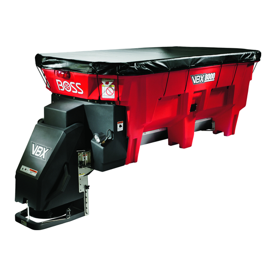
- Page 1 Form No. VBS14720 Rev A Owner's Manual VBX 6500/8000/9000 V-Box Spreader *VBS14720* A Register at www.bossplow.com. Original Instructions (EN)
-
Page 2: Table Of Contents
This product complies with all relevant European serious injury or death if you do not follow the directives; for details, please see the separate product recommended precautions. specific Declaration of Conformity (DOC) sheet. BOSS Products limited consumer warranty and BOSS Products commercial warranty policies are located at g000502 www.bossplow.com. -
Page 3: Safety
Safety Cleaning the Machine ........24 Storage ..............24 Troubleshooting ............25 Improper use or maintenance by the operator or ................. 25 owner can result in injury. To reduce the potential for injury, comply with these safety instructions and always pay attention to the safety-alert symbol , which means: Caution, Warning, or Danger—personal safety instruction. -
Page 4: Safety And Instructional Decals
• or rear gross-axle-weight ratings (FGAWR or Do not climb into or ride on the spreader. RGAWR) for the vehicle. • Keep your hands, feet, and clothing away from • This spreader is restricted to the use of dry, moving parts and mounting points. free-flowing salt, sand, and sand/salt mix. - Page 5 decalmsc18131b MSC18131 1. Crushing hazard—keep hands clear. decalvbs14307b VBS14307 1. Finger/hand entanglement hazard, pintle chain—keep hands clear. decalvbs14306b VBS14306 1. Warning—do not step here. decalvbs14305b VBS14305 1. Cutting/dismemberment hazard, spinner—keep hands clear. decalvbs14308b VBS14308 1. Entanglement hazard, auger—keep hands clear.
- Page 6 decalvbs14567b VBS14567 decalvbs14569b VBS14569 1. Loss of machine hazard—the ratchet straps must be secured at all times. 1. Work-light switch decalvbs14570b VBS14570 1. Finger/hand entanglement 2. Entanglement hazard, hazard, pintle chain—keep auger—keep hands clear. hands clear. decalvbs14568b VBS14568 1. Dump switch...
-
Page 7: Setup
Setup Connect the red spade connector without the inline fuse to the center high-mounted, stoplight fuse if it is available (Figure Installing the Wire Harness Connect the white bullet connector to the rear tail-light ground wire using a quick-splice connector (Figure DANGER Connect the brown bullet connector to the... - Page 8 g266761 Figure 3 9. Red spade connector 1. Control module 5. Vehicle-side power/ground 13. Fuse (150 A) connector 2. Spreader-side main 6. Vehicle-side main harness 10. Red spade connector (with 14. Fuse block harness connector inline fuse) 3. Spreader-side 7. White bullet connector 11.
-
Page 9: Mounting The Spreader
The truck bed must be at least 1.68 m not extend past the truck box. (66 inches) long for the VBX 6500, at least 2.0 m (78 inches) long for the VBX 8000, and at least Remove and retain the carriage bolts securing 2.3 m (90 inches) long for the VBX 9000. -
Page 10: Installing The Tie-Down D-Rings
g265127 Figure 6 1. Slide-stop adjustment 2. Slide stop holes g029489 Figure 8 Torque the bolts to 28 N·m (19.7 ft-lb). 1. Bolt (1–1/2 inch) 4. Bedmount plate 2. Flat washer (3/8 inch) 5. Flat washer (3/8 inch) Installing the Tie-Down 3. -
Page 11: Building And Installing The Spacer
Building and Installing the Spacer Measure the distance from the front of the truck box to the spreader legs. Using 3.8 x 18.4 cm (1–1/2 x 7–1/4 inch) lumber, build the spacer as shown in Figure g029491 Figure 10 1. D-ring 2. -
Page 12: Installing The Spreader Controller
g029493 Figure 12 1. Controller display 5. Mounting bracket 2. Sliding bracket 6. Pan-head screws g029492 3. Sheet-metal screws 7. Thumb nut Figure 11 4. Carriage bolt 1. Adjustment assembly 4. Spinner assembly 2. Thumb screw 5. Cotter pin Connect the controller display to the sliding 3. -
Page 13: Product Overview
Product Overview g265128 Figure 13 1. Hopper cover 5. Dump switch 2. Material deflector 6. Pintle-chain tension adjustment 3. Spinner-height adjustment 7. Back cover 4. Front cover 8. Work-light switch Controls Dump Switch Become familiar with all the controls before you The dump switch activates the spreader and empties operate the spreader. -
Page 14: Spreader Controller
Work-Light Switch Main Screen The work-light switch activates the rear lights. Control Module The control module is located under the front cover. The LED on the module can be used to help with Troubleshooting (page 25). g029495 Figure 15 1. Feed speed dial 5. -
Page 15: Specifications
2. Mode button 5. Light Adjustment button 3. Vibrator Adjustment button Specifications Note: Specifications and design are subject to change without notice. VBX 6500 VBX 8000 VBX 9000 Length 2.4 m (94 inches) 2.9 m (115 inches) 3.1 m (123 inches) -
Page 16: Operation
Operation Note: Determine the left and right sides of the machine from the normal operating position. Adjusting the Height of the Ensure that the spreader is securely mounted to the vehicle and that the top screen is installed Spinner Assembly and closed. -
Page 17: Freeing A Clog
Adjusting the Material Use the controller to set the desired feed speed and spinner speed. Deflectors Note: You can adjust the feed and spinner speeds while the spreader is operating. You can adjust the material deflectors by inserting the deflector pins into the staggered holes around the If you plan to use the vibrator during spreading, spinner (Figure... -
Page 18: Unloading The Spreader
Unloading the Spreader Removing the Spinner Assembly Important: Do not leave material in the hopper as it could damage the machine. Position the spreader over a flat, dry surface. Position the spreader in the area where you Unplug the spinner harness from the main wire want to deposit the material. -
Page 19: Installing The Pintle-Chain Restrictor Plate (Optional)
Installing the Pintle-Chain Restrictor Plate (Optional) Pintle-Chain Models Only If the spreader flow is too fast, install the restrictor plate. If the spreader flow is too slow, remove the restrictor plate. Unplug the power/ground cable and the main harness from the wire harness. Remove the spinner assembly;... -
Page 20: Maintenance
Maintenance WARNING Failure to properly maintain the machine could result in premature failure of machine systems causing possible harm to you or bystanders. Keep the machine well maintained and in good working order as indicated in these instructions. CAUTION If you leave the key in the switch, someone could accidently start the engine and seriously injure you or other bystanders. - Page 21 g265129 Figure 24 1. Back cover g036955 Check the gap between the pintle chain and the Figure 26 cleanout tray (Figure 25). 1. Take-up bolt 2. Jam nut Note: The chain should hang 2.5 to 5 cm (1 to 2 inches) above the cleanout tray. Turn the left take-up bolt clockwise 1 to 3 revolutions.
-
Page 22: Controller Status And Error Indicators
Controller Status and Error • Feeder Error or Spinner Error icon—indicates that the feeder or spinner motor is disconnected or that Indicators there is a circuit issue The following icons and messages indicate that an error has occurred with your machine. Refer to Troubleshooting (page 25) for possible solutions. - Page 23 • • Feeder Motor Cool or Spinner Motor Cool fan Open Box icon—indicates that the top screen is icon—indicates that the motor has shut down and open. The spreader does not run until the screen is cooling for 3 minutes is closed.
-
Page 24: Cleaning
Cleaning Storage Unload the spreader; refer to Unloading the Cleaning the Machine Spreader (page 18). Remove the spreader from the truck using the Service Interval: Before each use or daily lift bars (Product Overview (page 13)). Empty the cleanout tray after every use. Wash and rinse the entire unit. - Page 25 Troubleshooting The controller has no power. The controller display is not on. Module Status Possible Cause Corrective Action 1-6. The LED is off or flashing green. 1. The controller is in Sleep mode. 1. Press any button to wake up the controller.
- Page 26 6-7. The LED is flashing green. 6. The 5-pin spreader harness is 6. Clean the 5-pin connector at the disconnected or has a faulty connection. bumper. Check the continuity on the blue and green wires. 7. The 4-pin controller connector has a 7.
- Page 27 Pre-Wet Error The center of the controller screen says Pre-Wet Error. Module Status Possible Cause Corrective Action 1-3. The LED is solid green. 1. The circuit to the pump is open. 1. Check for disconnected pump wires and connect them. 2.
- Page 28 Feeder Jam Error The left side of the controller screen says Feeder Jam. Module Status Possible Cause Corrective Action 1. The LED is solid green. 1. The auger or pintle chain is jammed. 1. Allow the spreader to clear the jam. Auger spreaders will pulse forward 3 times, then cycle between forward and reverse 4 times.
- Page 29 Spinner Error The right side of the controller screen says Spinner Error. Module Status Possible Cause Corrective Action 1-2. The LED is solid green. 1. The spinner motor is not connected to 1. Connect the spinner motor to the the module. module.
- Page 30 Spinner Motor Cool Error The right side of the controller screen says Spinner Motor Cool and there is a fan icon. Module Status Possible Cause Corrective Action 1. The LED is solid green. 1. The spinner circuit has reached Spinner 1.
- Page 31 Notes:...
Need help?
Do you have a question about the VBX 6500 and is the answer not in the manual?
Questions and answers