Advertisement
Advertisement
Table of Contents

Related Manuals for ACR Electronics MS-2000(M)


Summary of Contents for ACR Electronics MS-2000(M)
- Page 2 If you have questions regarding the contents of the manual, please contact our Technical Service Department at ACR Electronics, Inc., Telephone +1 (954) 981- 3333. Please be ready to provide the technician with the page number you wish to discuss. If you have a...
- Page 3 Table of Contents SECTION ONE- GENERAL _______________________________ 3 SECTION TWO- OPERATING INSTRUCTIONS _______________ 5 SECTION THREE- TESTING AND MAINTENANCE ___________ 7 APPENDIX A – WARRANTY, USEFUL LIFE POLICY, NOTICES 11 PLEASE READ ALL WARNINGS, CAUTIONS AND NOTES CAREFULLY Y1-03-0146E...
-
Page 4: Section One- General
SECTION ONE- GENERAL This publication provides maintenance and operating instructions for the MS-2000(M) Distress Marker Light. 1. Purpose The light is designed and intended to provide aircrew and other personnel with a high-intensity visual distress marker signal for use in the event of unscheduled abandonment of aircraft in isolated regions and other emergency and/or special operational mission situations. - Page 5 3. Theory of Operation All electrical circuitry comprising the MS-2000(M) strobe light is enclosed within its main body case assembly. These circuits operate to step up the battery voltage to a level sufficient to fire the xenon flash tube. This stepped-up voltage is so timed that the flash tube will fire between 40-60 flashes per minute.
-
Page 6: Section Two- Operating Instructions
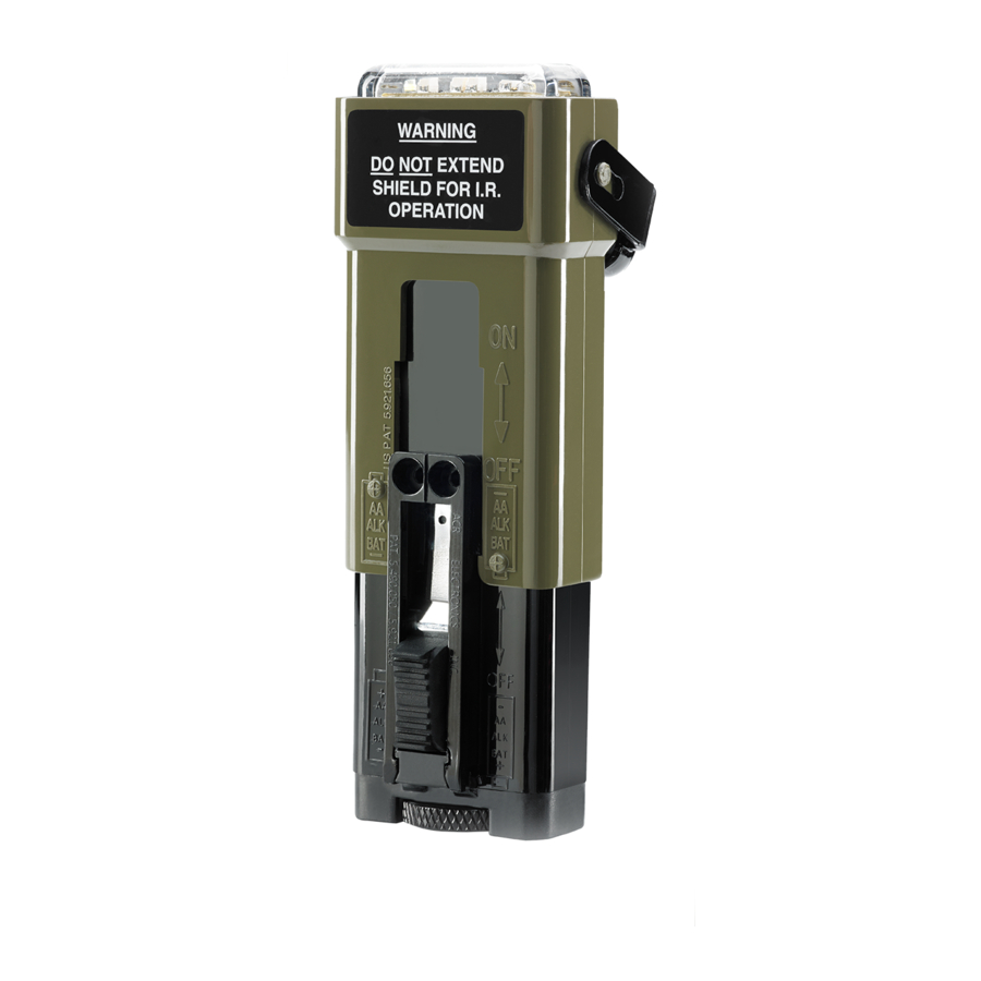
SECTION TWO- OPERATING INSTRUCTIONS a. Turn "ON" Slide switch up until it stops. within a few seconds. b. Turn "OFF" Slide switch down until it stops. The unit will stop operating. c. White Light With the flashguard shield in the retracted (stored) position, slightly raise the IR filter and rotate it either left/right 90°, push filter in to lock into place. - Page 7 IR light Stored Turn On Figure 3 e. Blue Light With the flashguard shield in the retracted (stored) position, slightly raise the IR filter and rotate it either left/right 90°. Then snap it in toward the side of the light to lock it into position. While holding the main body case with either hand, grasp the flashguard shield with the other hand and pull it up until it stops or a slight locking sound is detected, then release.
-
Page 8: Section Three- Testing And Maintenance
SECTION THREE- TESTING AND MAINTENANCE Light Leakage Test With the IR filter in its operation position (See Figure 3), turn the switch ON and observe that no light is transmitted through the sides of the case or the flashguard shield. Turn switch OFF. No light leakage is allowed in the IR mode. - Page 9 pressing the trap door down to turn the TS-23 "ON", or by removing the flashguard shield and inserting it into the tester. This is accomplished by separating the main body of the light from its flashguard shield. This separation is performed by holding the main body of the light with one hand while grasping the flashguard shield with the other and pulling in opposite directions.
- Page 10 Battery preventive maintenance visual checks will be performed during initial and periodic inspections of the light. 4. Preventive Maintenance Checks WARNING: flammable atmosphere or near an open flame a. MS-2000(M) Distress Marker Light (1) Check that the xenon flash tube lens is not cracked or discolored. (2) Check both the main body and flashguard shield cases for cracks or excessive abrasions.
- Page 11 7. Replacement Parts List (See Figure 1 for additional details) a. Flashguard shield assembly, ACR P/N 4463 . Battery door assembly, ACR P/N 9338 c. IR Filter, ACR P/N 4459 Item a. comes complete with blue filter, IR filter and labels. Item b.
-
Page 12: Appendix A – Warranty, Useful Life Policy, Notices
1 (one) year* from date of purchase or receipt as a gift. During the warranty period ACR Electronics, Inc. will repair or, at its option, replace the unit at no cost to you for labor, materials and return transportation from ACR. For further assistance, please contact our Technical Service Department at ACR Electronics, Inc.,5757...
Need help?
Do you have a question about the MS-2000(M) and is the answer not in the manual?
Questions and answers