Table of Contents
Advertisement
10527-T-800E-00
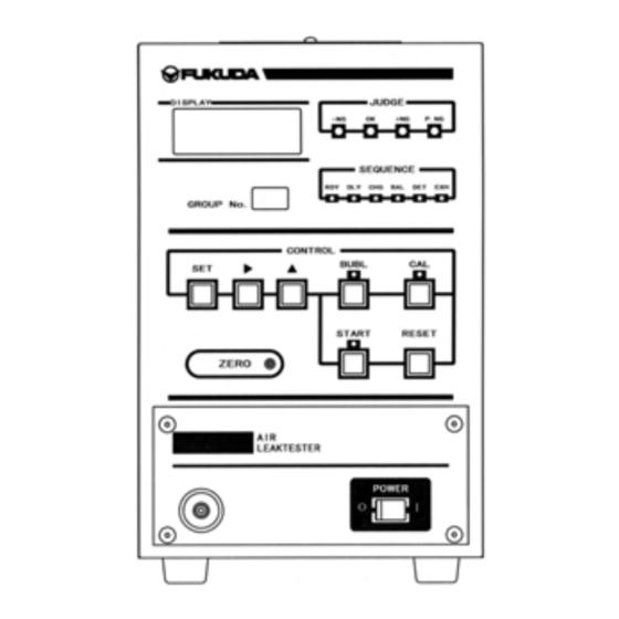
COMPACT AIR LEAK TESTER
MODEL
SPECIFICATIONS
DO YOU HAVE EVERYTHING?
OPTION
LINE CONNECTIONS
■
Declaration
・This design documents is outline specification for system design which is extracted from operation manual
(10527-T-001E-05).
The above contents page numbers is mentioned the page numbers of operation manual.
For about details of operation and testing procedure, please refer to operation manual.
・The contents of this manual may be modified without notice due to function and performance improvements.
・This manual has been written with care to provide the user with helpful and useful information. Please
contact your local FUKUDA distributor if there are any inaccuracies or questions of concern.
・Do not use this tester for any purpose other than testing air leaks.
・For best operating results and optimum efficiency, read this instruction manual thoroughly
to understand the tester's many functions prior to operation.
・Reprinting or duplicating this manual partially or completely is prohibited unless permitted by
FUKUDA CO., LTD.
■
Trademark
Company names and product names being used in this manual are the registered trademarks of
their respective holders.
DESIGN DOCUMENT
FL-296 SERIES
Contents
・・・・・・・・・・・・・・・・・・・・・・・・・・・・・・・・・・・・
・・・・・・・・・・・・・・・・・・・・・・・・・・・・・
・・・・・・・・・・・・・・・・・・・・・・・
・・・・・・・・・・・・・・・・・・・・・・・・・・・・・・・・・・・・
・・・・・・・・・・・・・・・・・・・・
・・・・・・・・・・・・・・・・・・・・・・
・・・・・・・・・・・・・・・・・・・・・・・・・・・・・
・・・・・・・・・・・・・・・・・・・・・・・・・・
・・・・・・・・・・・・・・・・・・・・・・・・
・・・・・・・・・・・・・・・・・・・・・・・・
http://www.fukuda-jp.com
・・・・・・・・・・・・・・・・・
6
7
8
9
14-15
16-17
18-19
20-35
60-63
65
72-74
Advertisement
Table of Contents

Subscribe to Our Youtube Channel
Related Manuals for Fukuda FL-296 Series

Summary of Contents for Fukuda FL-296 Series
- Page 1 ・This manual has been written with care to provide the user with helpful and useful information. Please contact your local FUKUDA distributor if there are any inaccuracies or questions of concern. ・Do not use this tester for any purpose other than testing air leaks.
- Page 2 OUT LINE TESTER MODEL ■ OUT LINE TESTER MODEL ① ② ③ ④ ⑤ ⑥ - FL-2 MODEL ① MODEL Symbol Permissive Leak rangeApplication Application Middle Leak Detection ±0.01~9.99 kPa Small Leak Detection ±1~999 Pa ② CALIBRATOR (BUILT IN) Symbol With/Without Calibrator Remarks Without Calibrator...
-
Page 3: General Specifications
TESTER SPECIFICATIONS ■ PERFORMANCE SPECIFICATIONS ◆ Testing Method: Differential Pressure Comparison ◆ Leak Pressure Range・Measurement Accuracy Leak Pressure Measurement Measurement Sensor Accuracy MODEL Range (Including hysteresis) FL-286 ±0.01~9.99kPa ±5%F.S.(10.00kPa) FL-296 ±1~999Pa ±5%F.S.(1000Pa) Direct Pressure Sensor Accuracy Measurement Sensor Accuracy MODEL Pressure Measurement Range (Including hysteresis) -10.0~10.0kPa... - Page 4 Confirm the following points prior to operating the tester. If there are any problems such as incorrect specifications, missing accessory parts or damages with the delivered items, please contact your FUKUDA agent. Please compare the model numbers described below with the number indicated on the tester’s nameplate.
- Page 5 OUTLINE OPTIONS ○ OPTION ⑥ EXTERNAL OPTIONS MODEL COMMON OPTION REMARKS Manual Calibrator0.1mlF.S. (Externa) Mounted in the rear of the work port manual valve. Manual Calibrator1.0mlF.S. One of C1 or C3 is chosen. (External) Positive Pressure Standard Spec. FR53 Filter/Regulator Unit Pressure Setting Range:0.02 ~...
- Page 6 INSTALLATION INSTRUCTIONS ■ INSTALLATION INSTRUCTIONS Air leak testers detect leaks by reading out precise pressure (air condition) alterations. Thus, it requires different handling instructions from other standard precision equipment. Tester must be in a stable position. ・ Be sure to install the tester on a level surface. Vibrations or earthquakes may cause the tester to fall and cause injury to operators.
- Page 7 INSTALLATION INSTRUCTIONS ● INSTALLATION LAYOUT Use a pair of brackets and the supplied screws. Front/Rear Mounting Side Mounting ・Without calibrator ・Both with and without calibrator ・With calibrator ※Dimensions in front & in the rear differ in case Manual Calibrator is mounted, or not. ●...
- Page 8 AIR PIPE CONFIGURATIONS Air leak testers are designed to detect a leak by sensing a small change in pressure. ☆ For that reason, you must ensure that the air leak tester’s piping differs from normal piping. Please keep this in mind to help obtain accurate and reliable leak testing. PRIMARY PRESSURE REGULATOR Adjust to: (approx.)
- Page 9 AIR PIPING CONFIGURATION 空圧源 COMPRESSED AIR SOURCE: CLAMPING EQUIPMENT クランプ装置 供給エアーにはクリーンなものを御使用下さい。 Water and oil intrusion often cause the pressure sensor in the air leak tester to malfunction. Be Regulators to adjust the cylinder driving pressure must be provided separately 主配管 Main air source シリンダー駆動圧力を調整する減圧弁は、個別に設けて下さい。...
- Page 10 ELECTRIC WIRING CONFIGURATION ● ELECTRIC WIRING PRECAUTIONS BEFORE WIRING AIR LEAK TESTER, BE SURE TO TURN OFF THE MAIN POWER SWITCH. (Unplug the tester from the AC power source) Select appropriate wires and material according to use, considering voltage and current ●...
- Page 11 ELECTRIC WIRING CONFIGURATION REMOTE TERMINAL BOARD FL-2□□□-0 FL-2□□□-2 AIR LEAK TESTER CONTROL SIGNAL Code Meaning Connection *1 Specification Connection *1 Specification Control testing and bubble testing procedures Input signal Input signal Reset signal ・ START Start of air leak test. (Photo coupler) (Photo coupler) RESET...
- Page 12 ELECTRICAL AND AIR PIPE LINE CONNECTIONS ■ CONNECTION FOR LEAK SIDE TESTING (Outside Pressure Method) SOL2 SOL2 P.SW COM- 9・10 ① TEST PRES. REGULATOR AIR.SUP WORK Work ◎ COMPRESSED MASTER AIR SOURCE CAPSULE 3-WAY VALVE EXH OPEN TO ATMOSPHERE Air Leak Tester SPECIFICATION REQUIREMENTS FOR 3-WAY VALVE ARE SHOWN IN THE FIGURE ABOVE ●...
- Page 13 ELECTRICAL AND AIR PIPE LINE CONNECTIONS ● CONNECTION FOR LEAK TESTING USING VACUUM PRESSURE (Vacuum Source Method) ① P.SW COM- 9・10 ◎ AIR.SUP VACUUM AIR SOURCE Work WORK TEST PRES. REGULATOR MASTER Master Air Leak Tester Mount the vacuum breaker in location ① If there is potential for oil or other materials to reverse flow. In the figure above, →...
- Page 14 ELECTRICAL AND AIR PIPE LINE CONNECTIONS ● CONNECTING THE EXHAUST BYPASS UNIT (COMPRESSED AIR PRESSURE MEASUREMENT) SOL3 SOL3 ◎ A.P.SUP 400~700 kPa WORK ◎ AIR.SUP MASTER TEST PRES. SUP. FE-20 Work WORK Master MASTER ① EXH Close the exhaust port with the designated plug for FE-20 (accessory) Air Leak Tester In the figure above, →...
- Page 15 ELECTRICAL AND AIR PIPE LINE CONNECTIONS ● CONNECTING THE PRESSURE VERIFICATION SWTICH P.SW COM- 9・10 PRESSURE REDUCING VALVE Pressure Switch FOR LEAK TESTING AIR.SUP ◎ COMPRESSED Work WORK AIR SOURCE MASTER Master EXH Air Leak Tester The figure above is applied to connections when measuring under positive pressure. In the figure above, →...
- Page 16 ELECTRICAL AND AIR PIPE LINE CONNECTIONS ● WORK CLAMPING CYLINDER CONTROLLED BY LIMIT SWITCHES SOL1 SOL1 CYLINDER WORK CLAMPING CYLINDER CONTROL VALVE ① LMT1 LMT2 ◎ ② COM- 9・10 ③ UNCLAMPING SWITCH COM+ 11・12 CLAMPING SWITCH Connect + line to ①, and -line to ②. For a 3-wire cylinder, connect power line to ③. ●...
- Page 17 ELECTRICAL AND AIR PIPE LINE CONNECTIONS ● WORK CLAMPING CYLINDER CONTROLLED BY A DLY TIMER SOL1 SOL1 CYLINDER DRIVING WORK CLAMPING CYLINDER SOLENOID VALVE ◎ When selecting a cylinder driving solenoid valve, please make your selection according to the specifications indicated: ・Driving Voltage : FL-2□□□-0:AC100V 50/60HZ FL-2□□□-2:To accord with external valve power source specs.
- Page 18 ELECTRICAL AND AIR PIPE LINE CONNECTIONS ● CONTROL BY LEFT/RIGHT HAND SWITCH RESET SWITCH LEFT SWT RIGHT SWT START SWITCH RESET START GROUP SELECT SWITCH ① CH1 ② CH2 COM- 9・10 The operation procedure for the above connection is described as below: ・Emergency Stop: Press either one of the two reset switches.
- Page 19 ELECTRICAL AND AIR PIPE LINE CONNECTIONS USEFUL TECHNICAL INFORMATION EFFECTIVE USE OF A CORE As you may already know, leak detection through air leak testing is based on the principle that pressure is reduced when there is a leak. This implies that even if there is the same degree of leak, depending on the internal volume of the tested works, the pressure reduction rate will also vary.
- Page 20 ELECTRICAL AND AIR PIPE LINE CONNECTIONS ● CONNECTION WITH THE PLC (PROGRAM LOGIC CONTROLER RESET START BUBL COM- 9・10 COM O1 17・18 COM O2 23・24 P.NG シーケンサー The load capacity for the relays in tester should be maintained within the specified value( AC125V 0.4A ●...
- Page 21 ELECTRICAL AND AIR PIPE LINE CONNECTIONS ● CONTROL TIMING BY PLC Starting a Measurement Upon receipt of a measurement starting signals (START or BUBL.), the air leak tester will start within 0.5 seconds. For the verification of the starting status of the air leak tester by use of RDY signal, follow the timing of the RDY signal indicated below CLOSE OPEN...
- Page 22 ELECTRICAL AND AIR PIPE LINE CONNECTIONS ■ TIME CHART PROCESS READY OK WORK EVALUATION READY ITEM RDY DLY CHG BAL DET EXH RDY RESET START BUBL P.SW LMT1 LMT2 CH 1 CH 2 OK +NG -NG P.NG RDY END ERR SOL1...
- Page 23 ELECTRICAL AND AIR PIPE LINE CONNECTIONS S.LEAK DETECTION READY READY REMARKS RDY DLY CHG BAL DET EXH RDY OPTION P.SW DIF. PRES VALUE HOLD S. LEAK DETEC ZERO CORRECTION ZERO CORRECTION 0.6sec 0.1sec DLY CHG DLY BAL EXH TIMER TIMER TIMER TIMER IMER...
- Page 24 ELECTRICAL AND AIR PIPE LINE CONNECTIONS ■ TIME CHART READY L.LEAK DETECTION READY PROCESS ITEM RDY DLY CHG BAL EXH RDY RESET START BUBL P.SW LMT1 LMT2 CH 1 CH 2 OK +NG -NG P.NG RDY END ERR SOL1 SOL2 SOL3...
- Page 25 ELECTRICAL AND AIR PIPE LINE CONNECTIONS PRESSURE ERROR DETECTION *3 READY READY REMARKS RDY DLY CHG BAL EXH RDY OPTION *2 P.SW DIF. PRES PRES. ERROR DETC. PRES. ERROR DETC. NO P.SW INPUT AT THE END PRES. LESS THAN SET VALUE FOR TEST OR NO OF THE CHG SEQUENCE P.SW INPUT AT THE END OF...
- Page 26 ELECTRICAL AND AIR PIPE LINE CONNECTIONS ■ TIME CHART READY CALIBRATION READY PROCESS ITEM RDY DLY EXH BAL DET EXH RESET START BUBL P.SW LMT1 LMT2 CH 1 CH 2 OK *2 +NG *2 -NG *2 P.NG RDY END ERR SOL1...
- Page 27 ELECTRICAL AND AIR PIPE LINE CONNECTIONS READY BUBBLE READY REMARKS RDY DLY CHG EXH RDY OPTION *3 P.SW 0.1sec EXH DLY DLY TIMER TIMER TIMER *3 With (-) sign in P.NG setting, SOL3 signal continues for a duration indicated by a light gray bar. With (+) sign in P.NG setting, SOL 3 signal continues a duration indicated by a light gray and black bar.
- Page 28 RS-232C CONNECTION ☆ This is an optional function. The test data can be sent to an external computer and other devices using this RS-232C output. The transmission data is as follows. • Transmit measurement data • Transmit measurement condition • Receive measurement condition RS-232C Output Specifications.
- Page 29 RS-232C CONNECTION Data Transmission Procedures and Data Composition ● • Data is transmitted immediately following the end of the EXH (exhaust) sequence. • Test condition configuration and readouts are only available while in the RDY state. 1) Receive settings from an external source. (1) Make sure that the air leak tester is in the RDY state.
- Page 30 RS-232C CONNECTION 2) Transmit the air leak tester settings data (1) Set the air leak tester to RDY status. * The RDY status can be confirmed by viewing the RDY signal from REMOTE. * Communications will not take place other than in RDY status. If not in the RDY state, input signals will be ignored.
- Page 31 Test Data Communication Sample GROUP TEST NUMBER JUDGMENT RESULT MEASURED VALUE TEST PRESSURE COMMAND 1 2 3 4 5 6 7 8 1 2 3 4 5 6 7 8 1 2 3 4 5 6 7 8 1 2 3 4 5 6 7 8 1 2 3 4 5 6 7 8 BYTE OK WORK TEST 1 0 0 CR...
- Page 32 PRINTER CONNENCTIONS ☆ This function is optional ● Print out evaluated data by connecting an external printer (e.g. FP-100) to the printer output port located on the rear panel of the air leak tester. ● Following is the specifications for printer output. ・Text code ASCII ・Output Spec.
- Page 33 SUPPLEMENT EXTERNAL DIMENSIONS ● EXTERNAL DIMENSIONS ■FL-286・296-□-0 Series...
- Page 34 SUPPLEMENT EXTERNAL DIMENSIONS ● EXTERNAL DIMENSIONS ■FL-286A・286B・296A・296B-□-0 Series...
- Page 35 SUPPLEMENT EXTERNAL DIMENSIONS ● EXTERNAL DIMENSIONS ■FL-286A,286B,296A,296B-□-2 Series...
Need help?
Do you have a question about the FL-296 Series and is the answer not in the manual?
Questions and answers