Table of Contents
Advertisement
Quick Links
Advertisement
Table of Contents

Summary of Contents for Ecumaster PMU-16
- Page 1 ECUMASTER PMU-16/PMU-16DL Preliminary Manual (04.06.2018, rev. 1.02) Page 1...
- Page 2 • ECUMASTER assumes no responsibility for damage caused by incorrect installation and/or configuration of the device! • To ensure proper use of ECUMASTER PMU and to prevent risk of damage to your vehicle, you must read these instructions and understand them thoroughly before attempting to install this unit.
-
Page 3: Table Of Contents
Downloading the PMU software ..................8 Installing PMU software ..................... 8 CONNECTING PMU TO PC ....................11 CAN – USB interface ....................... 11 ECUMASTER USBtoCAN interface ................11 ECUMASTER USBtoCAN pinout ..................12 Connecting USB interface, wiring schematics ..............13 PMU status ........................13 CAN protocol, CAN topology ................... - Page 4 Output Pin signaling and status ..................30 WIRING ..........................31 Basic diagram ........................31 Wire Size .......................... 32 Load examples for popular devices ................. 32 ANALOG INPUT WIRING ....................33 Wiring schematics ......................33 Analog Sensor ......................... 36 OUTPUT DEVICES ......................37 Power Output ........................
-
Page 5: Ecumaster Pmu
It can communicate and work in tandem with other ECUMASTER CAN devices. It is equipped with over and under current protection, surge protection, 3D gyroscope, accelerometer, LED Status lights, Soft Start, Pulse Width Modulation with Duty Cycle control and more. -
Page 6: Specification
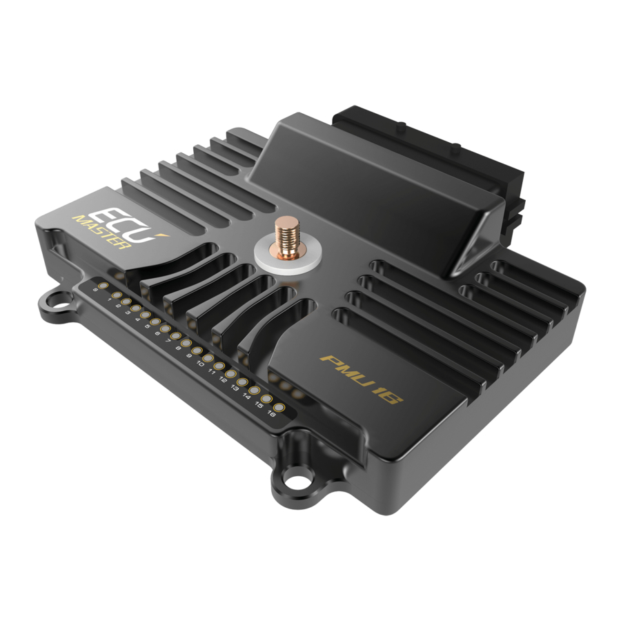
Connectors 1 x 39 Automotive connector 1 x M6 stud for battery connection PC communication CAN (Peak CAN, ECUMASTER USBCAN, Kvaser) Multiple PMUs Up to 5 PMUs can work in tandem OUTPUTS 10 x high side 25A output Overcurrent and overheating protection. - Page 7 Analog Inputs 16 inputs, 10 bit resolution, 0-5V (protected), with software selectable 10K Ohm pullup and pulldowns CAN Keypads 2 x Ecumaster keypads (4, 6, 8, 12 keys), LifeRacing PDU Keypad OTHER Output state indication 16 bicolor LEDs Accelerometer/Gyroscope 3D accelerometer with 3D gyroscope for logging and crash detection...
-
Page 8: Software Installation
Downloading the PMU software To configure PMU device a PMU Client must be used (both PMU16 and PMU16DL use the same client). To download PMU software please head to www.ecumaster.com/pmu page. Installing PMU software To install PMU software, double click the downloaded “PMUSetup_X_XXX_X.exe”. - Page 9 Choose which folder to install the PMU Client to. Choose wheter you want a desktop icon or not. Page 9...
- Page 10 This is the summary of your installation, if both the folder and icon choice are correct, press Install to proceed. If not, you can go back to make a quick correction. After the installation is finished, you can choose to launch PMU Client right away. Page 10...
-
Page 11: Connecting Pmu To Pc
Each interface must have its drivers installed. Interface must be bought separately. ECUMASTER USBtoCAN interface To use ECUMASTER USBtoCAN interface, user must be equipped in following items: USB A to USB B adapter to connect the interface to PC •... -
Page 12: Ecumaster Usbtocan Pinout
ECUMASTER USBtoCAN is equipped with 120Ohm CAN terminator which can be switched on or off by user. Picture below shows terminator switch location: ECUMASTER USBtoCAN pinout Page 12... -
Page 13: Connecting Usb Interface, Wiring Schematics
PMU Pinout section) must be used. Twisted pairing is also recommended. CANbus must also be terminated at both ends of the bus. ECUMASTER USBtoCAN is equipped with one terminator that can be switched on or off (See ECUMASTER USBtoCAN interface section). -
Page 14: Can Protocol, Can Topology
Client Orange Flashing Fast Device is performing Make Permanent operation Red Continuous Device Error - please contact the distributor or manufacturer directly CAN protocol, CAN topology CAN topology looks like this: CAN Topology For 1Mbit/s connection (CAN 1), following rules must be abided: Maximum unterminated cable length from device to CANbus is 30 cm •... -
Page 15: Using Pmu Software
USING PMU SOFTWARE Launching PMU software To run PMU software either doubleclick the icon on desktop, or use start menu to find it. Using PMU software When PMU Client is launched for the first time, user will be asked to enter the name of his device. All projects will then be saved to the directory corresponding to devices name. - Page 16 Project Tree, adding new Elements To upload current project to on-device flash memory, either use the Make Permanent button, or use F2 keyboard button. The PMU status LED will flash with orange color (See PMU Status section). To save a copy of your current project on hard drive either use Ctrl+S keyboard shortcut, or use the Clients toolbar.
-
Page 17: Pmu Client Workflow
On the left, there is a Tree View double clicking any item on it, will bring up it's window to current desktop. Tree View PMU Client workflow PMU Client workflow is really simple. You can monitor parameters of your channels, make adjustments, follow the graph log to understand channels behavior, you can create elements, then use those to control other elements or channels. - Page 18 These are just two examples of how PMU Client can be used, but the possibilities are endless. Page 18...
-
Page 19: Element Types
ELEMENT TYPES Analog Input Analog inputs are input devices connected directly to the PMU. Below is the list of analog inputs supported by PMU. Switch - Active High • Switch - Active Low • Rotary Switch • Analog Sensor • Head to Wiring section to see wiring diagrams for each type of analog input. -
Page 20: Number
Number Number is simply an integer. It can be either a typed in constant or value of chosen channel. Number is mostly used for comparison or to control Duty Cycle in Pulse Width Modulation (See section). Function Function is one of the most important elements. It can be used to create a set of rules, conditions to Power on an output device. -
Page 21: Functions
FUNCTIONS Main Principle The idea behind functions is to create a set of rules by combining different operations for various channels or elements. This set of rules is evaluated to a logical true (1) or false (0) result. Function then can be used to turn, for example, Power Output on or off. Quick example could be turning the secondary fuel pump on if a fault is detected on the primary one. - Page 22 Operations with state Toggle Toggles between 0 and 1 whenever Channel triggers a signal edge. It can be set to trigger by Rising Edge or Falling Edge If Default State is checked, default state of the Function after device is turned on will be 1, otherwise 0. Toggle remembers its last state, therefore if Channel signal is lost, Toggle will remain in the last steady state.
-
Page 23: Function Examples
Function examples We want the secondary fuel pump to turn on if a fault is detected on the first one or when fuel pressure drops below or is equal to 400kPa. To do this, we need to create a new function, let's call it f_switchPumps . - Page 24 And the final function will look like this: Switch Pumps function he flow diagram for that function: Switch Pumps function diagram Page 24...
-
Page 25: Channel Logging
Another diagram example of Fan Output: Fan Output function diagram example CHANNEL LOGGING Graph Log PMU Client is equipped with a tool to show channels graph in real time. There are two ways to add a channel to the graph. First way is to right click on the graph log window, then select Add and type the channels name. -
Page 26: Logging Frequency
Logging Frequency You can change the logging frequency of a channel by right clicking the channel on graph log, then selecting Set Log Frequency and choosing the desired frequency. Another way is to use Logged Channels window (Tree View → Logged Channels) . In that window you can see how parameters are groupped and their logging frequency. -
Page 27: Pmu Pinout
PMU PINOUT Page 27... -
Page 28: Output Pins
Output Pins There are 16 output pins for you to use, 10 25A pins and 6 15A pins. They can be also used in parallel to increase current capacity (See Using output pins in parallel section) All Pins are equipped with over and under current protection, short circuit protection, as well as thermal protection. -
Page 29: Output Load Balancing
Tree View → PMU window If you are experiencing high temperatures, it is advised to move the PMU to a colder place or provide better airflow to current location. Output Load Balancing Another way to handle high temperatures is to connect the devices that draw the most current in a way that the transistors for their Output Pins are not grouped up together. -
Page 30: Output Pin Signaling And Status
Output Pin signaling and status PMU has an ability to signal condition of each Power Output. It is displayed on the device itself and in PMU software. When a new Power Output is created, a special variable which represents the status of Power Output, called output_name.status is created as well. -
Page 31: Wiring
WIRING Basic diagram PMU Basic Diagram This is the basic PMU communication and connection diagram which contains few key elements: PC Communication takes place on CAN 1 as this is the CAN specified to use for PC • connection. CAN 1 has two 120 Ohm terminators on CAN bus. They are necessary, as PMU does not •... -
Page 32: Wire Size
Wire Size Suggested wire size for continuous current (chassis wiring, FLRY) < 5A 0.75mm^2 0.75mm^2 1.5mm^2 2.0mm^2 >=2.5mm^2 AWG 20 AWG18 AWG16 AWG14 AWG12 For the power connecter at least 25mm^2 (AWG3) is required ! Load examples for popular devices Device Inrush Current [A] Continuous Current [A]... -
Page 33: Analog Input Wiring
ANALOG INPUT WIRING Wiring schematics Most important thing to remember is that PMU has dedicated +5V Pin (See PMU Pinout section) can be used for things like rotary switch, active low switches and analog sensors. Below are basic wiring diagrams. Switch connected to GND with Pull Up •... - Page 34 PMU Client configuration: • Analog Input + Pullup configuration Switch connected to +5V Pin with pull down: • Page 34...
- Page 35 PMU Client configuration: Analog Input + Pulldown configuration Rotary switch • Page 35...
-
Page 36: Analog Sensor
PMU Client configuration: • Rotary Switch configuration Analog Sensor To connect analog Sensor, +5V and GND Pins must be used (See PMU Pinout section). Output from Analog Sensor should be connected as a regular Analog Input to PMU. Analog Sensor diagram: Analog Sensor diagram Page 36... -
Page 37: Output Devices
PMU Client Configuration: PMU Client analog sensor configuration OUTPUT DEVICES Power Output Power Outputs are elements that control external devices. You can set up the Minimum Current, Maximum Current, Inrush Current, Inrush Time, PWM, and mechanisms to switch the Power Output on or off. -
Page 38: Simple Power Output Setup
Simple Power Output Setup This is a quick example of two popular setups, their wiring diagrams and PMU Client configuration. Please note that output pins shown here are just an example. Power Output that is turned on as soon as PMU is turned on: •... - Page 39 Power Output that gets switched on by an Analog Input: • Power Output diagram example 2 PMU Client Configuration: Analog Input configuration example 2 Power Output configuration example 2 Page 39...
-
Page 40: Wipers
Wipers To connect wipers O8 Output Pin must be used for Slow Wiper output. This is the Pin provided to use and it's the only way to use the park switch ability. For fast wiper output any output pin can be used except for O8. -
Page 41: Blinkers
Blinkers Blinkers diagram Blinkers should be simply connected to PMU Output Pins. Three input channels should be used in this configuration - two channels to control blinkers, one channel to control hazard lights. PMU Client also provides special module designed to configure blinkers in easy way (Project Tree →... -
Page 42: Canbus Keyboard
CANbus Keyboard CANbus Keyboard can be connected to any CANbus. If CAN2 was chosen, user has the ability to change CAN2 speed for CANbus Keyboards such as Life Racing (Tree View → CANbus Setup). CAN connection must be terminated at both ends. It is possible to use CAN2 terminator from PMU (Tree View →... -
Page 43: Exporting Keyboard State
Power Output configuration for CANbus Keyboard: CANbus Keyboard power output configuration Exporting Keyboard state While configuring CANbus Keyboard, you can choose to broadcast the Keyboard state and buttons on chosen CANbus Interface, ID and frequency so that other device such as secondary PMU or EMU Black can acquire and use them. - Page 44 Keyboard status indicator configuration This example configures button k_button1 to display the value of pmu.status channel in the following way: Status Color Description None All Power Outputs are Off (pmu.status equal to 0) Green At least one Power Output is on and there is no under or over current condition (pmu.status equal to 1) Orange At least one Power Output is under current and there is no over current...
-
Page 45: Using Output Pins In Parallel
Using output pins in parallel PMU allows user to connect output pins in parallel to increase current capacity. Up to three output pins of the same amperage can be used, granting up to 75A continuous current. PMU Client configuration example: Power Output configuration with parallel pins INERTIA SWITCH PMU is equipped with a failsafe switch which gets triggered in case of a crash. -
Page 46: Master Retry Channel
MASTER RETRY CHANNEL Master Retry Channel allows user to perform reset of Power Outputs. If a Power Output has signaled a fault, due to either over or under current condition, triggering a Master Retry will reset it back to default state. Master Retry can be triggered by any channel or element. Master Retry configuration can be found in Tree View →... -
Page 47: Soft Start
Soft Start PMU has the ability to enable a Soft Start on 25A output Pins. Soft start should be used to prevent switch-on surges of greater altitude. By varying the time on and time off with chosen frequency and duration, a Power Output reaches its state gradually. Soft Start Disabled Soft Start Enabled Duty Cycle... -
Page 48: Using Flyback Diode
Duty Cycle can be either set to constant value, or controlled by a Channel. PMU Client Configuration Example: PWM Configuration example Using flyback diode PWM does introduce a bit of heat depending on the Device powered, and PWM settings. If you are experiencing Overheated status on any Pulse Width Modulated Power Output, a flyback diode can be used to eliminate flyback therefore lowering the output transistors thermal load. -
Page 49: Using Multiple Pmus
USING MULTIPLE PMUs Basic Diagram CAN communication diagram To use PMUs in tandem, it is recommended to use CANbus 1. Both devices must be connected to the same bus, terminated at both ends with 120 Ohm resistors. Up to five PMUs can be used at once. -
Page 50: Using Pmu Client With Multiple Pmus
Using PMU Client with multiple PMUs PMU Client allows up to 5 PMUs to be connected simultaneously. You can easily switch between them either using Menu Bar → Devices → Set Device #X or using Ctrl + Shift + X keyboard shortcut, where X is the device Number. -
Page 51: Can Stream
CANbus Export CANbus Export allows user to broadcast various informations on chosen CANbus. It is essential tool to communicate with other PMUs or ECUMASTER EMU Black device. CANbus Export can broadcast channel states, values, voltage readings, which then can be read using CANbus Input on second PMU or EMU Black. -
Page 52: Importing .Canx File
Importing .CANX File When creating a CANbus Export, you have the option to save this Export as a .CANX file. This file can be imported by other PMU to automatically create CANbus Mob with correct ID, Mob name and CANbus Inputs that correspond to exported Channel. Example: Create a CANbus Export, choose broadcasted channels and save it as a .CANX file Use Import .CANX option from Project Tree to open the .CANX file... - Page 53 As we can see, a CANbus Mob and CANbus Inputs were automatically created with correct ID Page 53...
-
Page 54: Standard Can Stream
Standard CAN Stream Standard CAN Stream(Tree View → Standard CAN Stream) gives user the ability to broadcast key PMU parameters over CAN bus to have an oversight. Parameters themselves are predefined, but user has the ability to broadcast only some part of them, on chosen CAN bus with chosen ID. - Page 55 o9.status, 3 bits Unsigned o9.active 1 bits o10.status, 3 bits Unsigned o10.active 1 bits o11.status, 3 bits Unsigned o11.active 1 bits o12.status, 3 bits Unsigned o12.active 1 bits o13.status, 3 bits Unsigned o13.active 1 bits o14.status, 3 bits Unsigned o14.active 1 bits o15.status, 3 bits...
- Page 56 BaseID + 4 Frequency: 62.5Hz ByteID Channel Data Width Data Type Range Resolution Offset Unit o1.current 8 bits Unsigned 0-63.75 0.25A/bit o2.current 8 bits Unsigned 0-63.75 0.25A/bit o3.current 8 bits Unsigned 0-63.75 0.25A/bit o4.current 8 bits Unsigned 0-63.75 0.25A/bit o5.current 8 bits Unsigned 0-63.75 0.25A/bit...
- Page 57 BaseID + 7 Frequency: 62.5Hz ByteID Channel Data Width Data Type Range Resolution Offset Unit o9.voltage 8 bits Unsigned 0-16.19 0.063V/bit o10.voltage 8 bits Unsigned 0-16.19 0.063V/bit o11.voltage 8 bits Unsigned 0-16.19 0.063V/bit o12.voltage 8 bits Unsigned 0-16.19 0.063V/bit o13.voltage 8 bits Unsigned 0-16.19 0.063V/bit...
-
Page 58: Document Revision History
DOCUMENT REVISION HISTORY Revision Date Changes 1.00 1.05.2017 - initial release 1.01 10.07.2017 - added information about ground connection with USBtoCAN 1.02 4.06.2018 - clarified outputs specification Page 58... - Page 59 Output Terminal Wire Current Name Comment Number Current Size (wipers)
- Page 60 Analog Terminal Type Pullup/ Name Comment Number Pulldown...
Need help?
Do you have a question about the PMU-16 and is the answer not in the manual?
Questions and answers