Advertisement
Quick Links
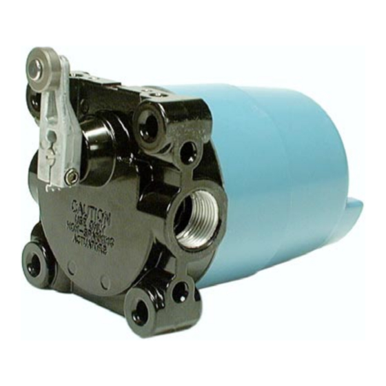
Installation and Service Instructions for CX Weather-Sealed
Explosion-proof Switches
0518
WARNING
IF USED IN APPLICATIONS CONCERNING HUMAN
SAFETY
•
Only use NC direct opening ("positive
opening"/"positive break") contacts, identified by the
symbol
.
•
Do NOT use flexible/adjustable actuators. Only use
actuators designed for safety applications.
•
Do NOT defeat, tamper, remove, or bypass this
switch.
•
Hazardous voltage, disconnect power before
servicing.
•
Strictly adhere to all installation and maintenance
instructions.
•
Consult with local safety agencies and their
requirements when designing a machine-control
link, interface and all control elements that affect
safety.
Failure to comply with these instructions could
result in death or serious injury.
GENERAL INFORMATION
Sealed construction for Honeywell CX explosion-
proof switches provides protection from the entry of
water, dust and oil as defined in NEMA 3, 4, 4X, 6,
6P, 13, and IP66/IP67 as defined in IEC 529.
CX Series products with conduit types ¾-14NPT
also meet the North American Hazardous Locations
Designation: Class I, Group C and D; Class II,
Groups E, F and G. CX listings beginning with
numbers 14, 16, 24, 26, 36, or 84 (example: 14CX1)
also meet Class I, Group B. These explosion-proof
and weather-sealed switches are protected from
flammable hydrocarbon atmospheres, metal dust,
coal dust, and grain dust, and comply with UL
Standard: UL 894 and UL 1203, CSA Standard:
C22.2 no. 25-1966, C22.2 no. 30-M1986.
Select CX Series products also meet the European
Hazardous Locations Designation: EExd IIC T6
category II 2 GD, KEMA 01ATEX2111X and
complies with the European Directive on Equipment
and Protective Systems Intended for Use in
Potentially Explosive Atmospheres (94/9/EC)
commonly referred to as the ATEX Directive.
Sensing and Control
Compliance with the Essential Health and Safety
Requirements has been assured by compliance with
EN50014 1997, EN50018 1994 and EN50281-1-1.
The European-approved products have a
temperature range of –40 °C to 70 °C [–40 °F to
158 °F], and when used within the maximum voltage
and current specified on the product will have no
heating problems. Notice: As ambient temperature
approaches 60 °C [140 °F], the cable entry can be
70 °C [158 °F] or higher. Cable branching can be
80 °C [176 °F] or higher, making it important to select
cable that meets these requirements.
Application Note: Enclosures are based, in
general, on the broad definitions outlined in NEMA
standards. Therefore, it will be necessary for the user
to determine that a particular enclosure is adequate
when exposed to the specific conditions that might
exist in intended applications. Except as might
otherwise be noted, all references to products
relative to NEMA enclosure types are based on
MICRO SWITCH evaluation only.
IMPORTANT: Switches without shaft re-storing
force do not have overtravel stops. On switches with
potentiometers, use care to insure that overtravel
does not exceed 125° in the application and during
set-up.
LEVER POSITIONING
Loosen the screw with a 9/64 inch hexagon key
wrench, move the lever to the desired position and
securely tighten the screw until the "teller tab" can no
longer be moved by hand. Then tighten the screw
another 1/8 to 1/4 turn to assure that the lever is tight
on the shaft. Hexagon key wrenches are provided in
adjusting tool set LSZ4005 for this purpose.
CAM ADJUSTMENT
Pretravel, overtravel, and actuation sequencing
can be adjusted and/or modified in the field. No tools
are required.
To Adjust Plunger Types:
1. Lift cam follower.
ISSUE 4
PK 88136
Advertisement

Related Manuals for Honeywell CX Series


Summary of Contents for Honeywell CX Series
- Page 1 UL Standard: UL 894 and UL 1203, CSA Standard: C22.2 no. 25-1966, C22.2 no. 30-M1986. Select CX Series products also meet the European Hazardous Locations Designation: EExd IIC T6 category II 2 GD, KEMA 01ATEX2111X and...
-
Page 2: Replacement Parts
4. When cam wheel has been rotated to desired location, release cam wheel to engage with mating shaft disc. 5. Release cam follower Rotary Switch Assembly CX Wiring Methods Honeywell recommends that conduit be installed per NEC articles 501-4 and 501-5. 2 Honeywell • Sensing and Control... -
Page 3: Wiring Diagram
0.5 A, 125 Vdc, 0.25 A, 250 Vdc. 250 Vdc. Pretravel, max. 2,5 mm [0.10 in] Differential Travel, 1 mm [0.04 in] 2 mm [0.08 in] 1 mm [0.04 in] max. Overtravel, min. 4,75 mm [0.19 in] Honeywell • Sensing and Control 3... - Page 4 7. Return shaft to final position and check for 20 then a half turn CW (back to initial position). mA. Adjust span trimmer if necessary. NOTE: Honeywell recommends repeating Procedure 3 after 50,000 operations. 4 Honeywell • Sensing and Control...
- Page 5 (5 FULL THREADS MIN) (5 FULL THREADS MIN) 25,4 20,3 8X Ø 7,3 X 17,8 DEEP HOLE FO R 5/ 16-18 UNC 1.00 25,4 INTERNAL FORMED THREADS 1.00 1 THESE HOLES NOT FURNISHED ON 80CX SERIES Honeywell • Sensing and Control 5...
- Page 6 Honeywell web site or call: 1-800-537-6945 USA/Canada 1-815-235-6847 International 1-815-235-6545 USA INTERNET www.honeywell.com/sensing info.sc@honeywell.com Sensing and Control www.honeywell.com/sensing Honeywell 11 West Spring Street Freeport, Illinois 61032 PK 88136-4-EN IL50 GLO 404 Printed in USA Copyright 2004 Honeywell International Inc. All Rights Reserved.