
Related Manuals for GE P50 Agile P253


Summary of Contents for GE P50 Agile P253
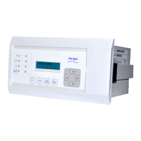
- Page 1 Grid Solutions P50 Agile P253 Technical Manual Motor Protection Relay Hardware version: A Software version: 01 Publication reference: P253/EN M/C...
- Page 2 Conformity This product complies with the directive of the Council of the European Communities relating to electromagnetic compatibility (EMC directive 2014/30/EU) and product safety (Low-voltage directive 2014/30/EU). This conformity is the result of a test conducted in accordance with the product standard EN 60255- 26 for the EMC directive, and with the product standard EN 60255-27 for the low voltage directive.
- Page 3 P50 Agile P253 1 Introduction INTRODUCTION CHAPTER 1 P253/EN M/C...
- Page 4 P50 Agile P253 1 Introduction P253/EN M/C...
- Page 5 P50 Agile P253 1 Introduction CHAPTER OVERVIEW This chapter consists of the following sections: Chapter Overview Introduction Features 2.1.1 Protection & Control 2.1.2 Measurement, Recording & Post Fault Analysis 2.1.3 Front Panel Interface 2.1.4 Communications Functional Overview Ordering Information P253/EN M/C...
- Page 6 P50 Agile P253 1 Introduction INTRODUCTION Features The P253 is a dedicated motor protection relay designed to protect motors in industrial networks and power plants. It offers essential protection functions for motors deployed in installations from LV to MV voltage levels. The P253 relay performs an important role in many industrial processes with its diagnostic features improving asset health monitoring.
- Page 7 P50 Agile P253 1 Introduction • 1A/5A CTs selection • SEF option • Latching of output contacts • Universal auxiliary power supply range • 2 Setting groups • Password protection • Self-supervision & internal diagnostics 2.1.2 Measurement, Recording & Post Fault Analysis •...
- Page 8 P50 Agile P253 1 Introduction • Rear EIA (RS) 485 port for SCADA communication • Multiple protocols - Modbus/ IEC60870-5-103 or DNP3.0 (ordering option) Functional Overview ANSI FUNCTION P253 Speed switch input (for stall rotor detection) • Prolonged start (excessive long start) •...
- Page 9 P50 Agile P253 1 Introduction ANSI FUNCTION P253 Earth current input 1x1 ph (or) • SEF current input 1x1 ph General Setting Groups Self diagnostics • Measurements • Event records • Fault records • Disturbance records • Start-up current record •...
- Page 10 P50 Agile P253 1 Introduction Ordering Information Variants Order Number 1 - 4 5 6 7 8 9 10 11 12-13 14 15 Model Type Basic Motor Protection Relay P253 Auxilliary Voltage Binary Input Threshold Voltage 24 – 230 V DC/AC 18V DC / 16V AC 24 –...
- Page 11 SAFETY INFORMATION CHAPTER 2...
- Page 12 Safety Information Pxxx...
- Page 13 Pxxx Safety Information HEALTH AND SAFETY Personnel associated with the equipment must be familiar with the contents of this Safety Information. When electrical equipment is in operation, dangerous voltages are present in certain parts of the equipment. Improper use of the equipment and failure to observe warning notices will endanger personnel. Only qualified personnel may work on or operate the equipment.
- Page 14 Safety Information Pxxx SYMBOLS Throughout this manual you will come across the following symbols. You will also see these symbols on parts of the equipment. Caution: Refer to equipment documentation. Failure to do so could result in damage to the equipment Warning: Risk of electric shock Earth terminal.
- Page 15 Pxxx Safety Information INSTALLATION, COMMISSIONING AND SERVICING LIFTING HAZARDS Many injuries are caused by: ● Lifting heavy objects ● Lifting things incorrectly ● Pushing or pulling heavy objects ● Using the same muscles repetitively Plan carefully, identify any possible hazards and determine how best to move the product. Look at other ways of moving the load to avoid manual handling.
- Page 16 Safety Information Pxxx Caution: NEVER look into optical fibres or optical output connections. Always use optical power meters to determine operation or signal level. Caution: Testing may leave capacitors charged to dangerous voltage levels. Discharge capacitors by rediucing test voltages to zero before disconnecting test leads. Caution: Operate the equipment within the specified electrical and environmental limits.
- Page 17 Pxxx Safety Information Caution: Where UL/CSA listing of the equipment is not required, a high rupture capacity (HRC) fuse type with a maximum current rating of 16 Amps and a minimum dc rating of 250 V dc may be used for the auxiliary supply (for example Red Spot type NIT or TIA).
- Page 18 Safety Information Pxxx PROTECTION CLASS 1 EQUIPMENT REQUIREMENTS Caution: Earth the equipment with the supplied PCT (Protective Conductor Terminal). Caution: Do not remove the PCT. Caution: The PCT is sometimes used to terminate cable screens. Always check the PCT’s integrity after adding or removing such earth connections. Caution: Use a locknut or similar mechanism to ensure the integrity of stud-connected PCTs.
- Page 19 Pxxx Safety Information Caution: Check integrity of the PCT connection. Caution: Check voltage and current rating of external wiring, ensuring it is appropriate for the application. PERIPHERAL CIRCUITRY Warning: Do not open the secondary circuit of a live CT since the high voltage produced may be lethal to personnel and could damage insulation.
- Page 20 Safety Information Pxxx DECOMMISSIONING AND DISPOSAL Caution: Before decommissioning, completely isolate the equipment power supplies (both poles of any dc supply). The auxiliary supply input may have capacitors in parallel, which may still be charged. To avoid electric shock, discharge the capacitors using the external terminals before decommissioning.
- Page 21 Pxxx Safety Information STANDARDS COMPLIANCE Compliance with the European Commission Directive on EMC and LVD is demonstrated using a Technical File. EMC COMPLIANCE: 2014/30/EU Compliance with EN60255-26:2009 was used to establish conformity. PRODUCT SAFETY: 2014/30/EU Compliance with EN60255-27:2005 was used to establish conformity. Protective Class IEC 60255-27: 2005 Class 1 (unless otherwise specified in equipment documentation).
- Page 22 Safety Information Pxxx Equipment with this marking is not itself suitable for operation within a potentially explosive atmosphere. Compliance demonstrated by Notified Body Type Examination Certificate. ATEX Potentially Explosive Atmospheres directive 94/9/EC for equipment.
- Page 23 P50 Agile P253 3 Hardware Design HARDWARE DESIGN CHAPTER 3 P253/EN M/C...
- Page 24 P50 Agile P253253 3 Hardware Design P253/EN M/C...
- Page 25 P50 Agile P253 3 Hardware Design CHAPTER OVERVIEW This chapter consists of the following sections: Chapter Overview Hardware Design Overview of Hardware Design Microcontroller with DSP Module 2.2.1 Microcontroller Module (processor board) Features Microcontroller and Analog Measurement Digital Input/Output Module...
- Page 26 P50 Agile P253253 3 Hardware Design HARDWARE DESIGN The P253 hardware comprises of the following main components: • Housing, consisting of a front panel and connections at the rear • Microcontroller module • Analogue input module • Digital input module •...
- Page 27 P50 Agile P253 3 Hardware Design Overview of Hardware Design The P253 hardware design overview is explained with the help of the schematic diagram. The P253 hardware consists of three sets of internal Current Transformers (CTs). These internal CTs are designed to cater to protection &...
- Page 28 P50 Agile P253253 3 Hardware Design E00276 Figure 2: Hardware design overview P253/EN M/C...
- Page 29 P50 Agile P253 3 Hardware Design Microcontroller with DSP Module The hardware is designed around 32 bit controller housed in small 100 pin SMD package. It is a high speed fix point controller having MIPS’s M4K® 32-bit core with 5-stage pipeline capable of operating up to 80 MHz.This controller is referred to as MCU (Microcontroller unit).
- Page 30 P50 Agile P253253 3 Hardware Design The MCU acquires analog values at the rate of 16 samples per cycle. Digital signal processing (DSP) performs powerful numerical algorithms which converts this signal in to equivalent vectors. Once the signal is converted into vectors, number of parameters are derived from it such as phase currents (Ia, Ib, Ic), positive sequence current (I1) and negative sequence current (I2).
- Page 31 P50 Agile P253 3 Hardware Design Human Machine Interface Module The HMI module is provided with 16x2 LCD, 8 numbers of soft feather touch keys and 8 numbers of LEDs for indication. The cover at right side of the front panel houses following: •...
- Page 32 P50 Agile P253253 3 Hardware Design 3-10 P253/EN M/C...
- Page 33 P50 Agile P253 4 Front Panel FRONT PANEL CHAPTER 4 P253/EN M/C...
- Page 34 P50 Agile P253 4 Front Panel P253/EN M/C...
- Page 35 P50 Agile P253 4 Front Panel CHAPTER OVERVIEW This chapter consists of the following sections: Chapter Overview Front Panel User Interface 2.1.1 LCD Display 2.1.2 Touch Keys 2.1.3 LEDs 2.1.4 RS 485 Port 2.1.5 USB Port P253/EN M/C...
- Page 36 P50 Agile P253 4 Front Panel FRONT PANEL Figure 1: Front panel SL no Label Function The green LED indicates that the IED is in correct working order. The green LED should be ON at all times. If there is an error in the hardware or software the LED will turn red.
- Page 37 P50 Agile P253 4 Front Panel SL no Label Function Feather touch key [►] is used to view the settings and to navigate through the menus and ► submenus. User Interface 2.1.1 LCD Display A backlit LCD display of 16 x 2 characters is provided for parameter and setting display. It also provides easy viewing of measurement, setting, fault records, date &...
- Page 38 P50 Agile P253 4 Front Panel 2.1.3 LEDs The P253 relay has 8 high-intensity LEDs for easy identification of fault type and ease of user interface. SL no Label Function LED 1 The green LED indicates that the IED is in correct working order. The green LED should be ON at all times.
- Page 39 P50 Agile P253 4 Front Panel Figure 2: USB port P253/EN M/C...
- Page 40 P50 Agile P253 4 Front Panel P253/EN M/C...
- Page 41 P50 Agile P253 5 Configuration CONFIGURATION CHAPTER 5 P253/EN M/C...
- Page 42 P50 Agile P253 5 Configuration P253/EN M/C...
- Page 43 P50 Agile P253 5 Configuration CHAPTER OVERVIEW This chapter consists of the following sections: Chapter Overview Configuration Changing the Settings Password Entry Menus 2.3.1 Default Display 2.3.2 Main Menu Contents 2.3.3 System Data Menu 2.3.3.1 View / Edit Settings 2.3.4 View Records Menu 2.3.4.1...
- Page 44 P50 Agile P253 5 Configuration 2.3.16.11 Group1 –Limit Nb Starts Submenu 2.3.17 Group 2 Menu Edit Settings 2.3.17.1 Configuration Flowcharts 2.4.1 Main Menu 2.4.2 View and Edit Settings 2.4.3 View System Data Menu Settings 2.4.4 Records Menu 2.4.4.1 View Records 2.4.4.2...
- Page 45 P50 Agile P253 5 Configuration 2.4.22 Group 1- Thermal Overload Submenu 2.4.22.1 View / Edit Settings (If setting is disabled) 2.4.22.2 View / Edit Settings (If setting is disabled) 2.4.22.3 View / Edit Settings (If setting is enabled) 2.4.23 Group 1- Loss of Load Submenu 2.4.23.1...
- Page 46 P50 Agile P253 5 Configuration CONFIGURATION Each product has different configuration parameters according to the functions it has been designed to perform. There is, however, a common methodology used across the entire product to set these parameters. This chapter describes an overview of this common methodology, as well as providing concise instructions of how to configure the device.
- Page 47 P50 Agile P253 5 Configuration Changing the Settings Step 1: Press the (4) key to move to the next option. SYSTEM DATA Step 2: Press the (- /6) key to move to the next option till the relay Language displays CB Open/Close setting...
- Page 48 P50 Agile P253 5 Configuration SYSTEM DATA Note: Press the CLEAR Key to DISCARD settings. Step 10: When the CLEAR key is pressed, it will discard the changes SET For Save and the relay will move to the next option.
- Page 49 After Power ON or when the PROT.RESET + EDIT keys are pressed the relay will display the following message. This window will flash momentarily showing the following. P50 Agile P253 Relay Name: P50 Agile P253, Relay Type : Motor Protection Motor Protect’n Then the control will automatically move to next option.
- Page 50 P50 Agile P253 5 Configuration Password protected window for “DATE AND TIME’’ settings i.e. Local DATE AND TIME Time Enable, Local Time Offset. DST Enable, DST Offset, DST Start, DST Start Day, DST Start Month, DST Start Mins, DST End, DST End Day, DST End Month, DST End Mins, RP Time Zone, SET Hours, SET Minutes, SET Seconds, SET Date, SET Month and SET Year.
- Page 51 P50 Agile P253 5 Configuration Password protected window for “GROUP 1’’ settings i.e. SYSTEM GROUP 1 CONFIG, OVERCURRENT, NEG SEQUENCE O/C, EARTH FAULT 1, EARTH FAULT 2, THERMAL OVERLOAD, LOSS OF LOAD, CB FAIL STALL DETECTION and LIMIT NB STARTS.
- Page 52 P50 Agile P253 5 Configuration Read-only USB Address This window shows the USB Address. Read-only USB Parity This window shows the USB Parity. None Read-only USB Baud Rate This window shows the USB Baud Rate 57600 Editable setting Password This window is for setting the new Password of the relay. The desired...
- Page 53 P50 Agile P253 5 Configuration 2.3.4 View Records Menu 2.3.4.1 View Records Menu Contents Menu to view Fault Record, Event Record, Maint Record and Alarm VIEW RECORDS record. This window is to view the Fault Record Fault Record This window is to view the Event Record...
- Page 54 P50 Agile P253 5 Configuration This window displays trip flag of stage 2: O/C, E/F-1 and E/F-2, Neg I>2: Sequence O/C, Lock Rotor, Stall trip. Note: This window is seen when relay operates for respective protection IN1>2: IN2>2: I2>2: function.
- Page 55 P50 Agile P253 5 Configuration This window displays date & time of fault. 17/11/14 16:15:30.225 2.3.4.3 View Event Records Menu to view Fault Record, Event Record, Maint Record and Alarm VIEW RECORDS record. This window shows the Fault Record Fault Record...
- Page 56 P50 Agile P253 5 Configuration This window will show Event Record Event Record This window will show Maintenance Record contents Maint Record This window shows Maintenance Record 1 Main’t Rec Num = This window shows the contents of the Maintenance Record 1.
- Page 57 P50 Agile P253 5 Configuration This window will show Alarm Record Alarm Record This window shows latest alarm. TCS Alarm This window shows the date and time of alarm. 24/09/2014 12:35:40:025 2.3.5 Measurement Menu 2.3.5.1 View Contents- Measurement 1 Submenu Menu to view the Measurement 1 &...
- Page 58 P50 Agile P253 5 Configuration This window shows secondary value of current in phase A and phase B. ia = 0.00 A ib = 0.00 A This window shows secondary value of current in phase C and = 0.00 A measured earth current.
- Page 59 P50 Agile P253 5 Configuration Submenu to view measurements related to motor : Measurement 2 Thermal State, Load Current, Time to Th Trip, Nb of Th Trip, Last Start Time, Last St current, Nb Hot st Allow, Nb Cold St Allow, Time to Next St, Total Nb of Strt, Nb of Emergency Rst, and Motor Run Time.
- Page 60 P50 Agile P253 5 Configuration This window shows time before permitted start Time to Next St This window shows the number of starts of the motor Total Nb of Strt This window shows number of emergency starts Nb Emergency Rst...
- Page 61 P50 Agile P253 5 Configuration Editable setting Emergency Rest By using the (+ /5) or (- /6) key, Emergency Restart can be set as Yes / No. 2.3.6.2 View / Edit settings (if all settings are enabled) Password protected window for “CB CONTROL” settings: CB CONTROL TCS Alarm, TCS Timer, CB Open S’vision (Enabled/Disabled), CB Open...
- Page 62 P50 Agile P253 5 Configuration Editable setting Close Pulse Time By using the Plus / Up arrow key (+ /5) or the Minus / Down arrow key (- /6) key, the desired Close Pulse Time can be set. The setting range 0.50S...
- Page 63 P50 Agile P253 5 Configuration Editable setting SET Hours By using the (+ /5) or (- /6) key, the desired SET Hours can be set. The setting range is from 00 to 23 in steps of 1. Editable setting SET Minutes By using the (+ /5) or (- /6) key, the desired SET Minutes can be set.
- Page 64 P50 Agile P253 5 Configuration Editable setting Local Time Offset By using the (+ /5) or (- /6) key, Local Time Offset can be set. The setting range is from -720 mins to 720 mins in steps of 15 mins...
- Page 65 P50 Agile P253 5 Configuration Editable setting DST End Mins By using the (+ /5) or (- /6) key, DST End minutes can be set. The setting range is from 0 to 1425 mins in steps of 15 mins. 60 Mins...
-
Page 66: Table Of Contents
P50 Agile P253 5 Configuration 2.3.8 Configuration Menu 2.3.8.1 View / Edit Settings Password protected window for “CONFIGURATION’’ settings: CONFIGURATION Restore Defaults, Active Settings, Copy From, Copy To, Setting Group 1 (Enabled/Disabled), Setting Group 2 (Enabled/Disabled), System Config (Enabled/Disabled), Overcurrent (Enabled/Disabled), Neg Sequence... - Page 67 P50 Agile P253 5 Configuration Editable setting Overcurrent By using the (+ /5) or (- /6) key, Overcurrent can be Enabled / Disabled. Enabled Editable setting Neg Sequence O/C By using the (+ /5) or (- /6) key, Neg Sequence O/C can be Enabled / Disabled.
-
Page 68: View / Edit Settings
P50 Agile P253 5 Configuration Editable setting Measure’t setup By using the (+ /5) or (- /6) key, Measurement Setup can be set as ABC / RYB. Editable setting Setting Values By using the (+ /5) or (- /6) key, Setting Values can be set as Primary / Secondary. - Page 69 P50 Agile P253 5 Configuration Editable setting Clear Events By using the (+ /5) or (- /6) key, Clear Events can be set as Yes / No (set ‘Yes’ to clear event data stored in memory) Editable setting Clear Faults By using the (+ /5) or (- /6) key, Clear Faults can be set as Yes / No.
- Page 70 P50 Agile P253 5 Configuration 2.3.11 Communication Menu 2.3.11.1 View / Edit Settings Password protected window for “COMMUNICATION” settings: COMMUNICATION RP1 Address, RP1 Baud Rate, RP1 Parity and RP1 Timesync. Editable setting RP1 Address By using the (+ /5) or (- /6) key, the desired RP1 Address can be set.
- Page 71 P50 Agile P253 5 Configuration Editable setting LED G : 8765 By using the (+ /5) or (- /6) key, LED GREEN can be set for desired function. Gen Strt 0000 ‘5’ corresponds to LED5, ‘6’ corresponds to LED6…’8’ corresponds to LED8 Set the value ‘1’...
- Page 72 P50 Agile P253 5 Configuration Note: The functions that can be assigned to relay, LED G, LED R and AND Logic are listed in Chapter 8: Monitoring and Control. 2.3.13 O/P Relay Configuration Menu 2.3.13.1 View / Edit Settings Password protected window for “O/P RELAY CONFIGURATION’’...
- Page 73 P50 Agile P253 5 Configuration Editable setting LED R HR/SR By using the (+ /5) or (- /6) key, the desired function for LED RED can be set as HR/SR (‘1’=HR /’0’=SR) 0000 Editable setting ANDEQ A Op Time By using the (+ /5) or (- /6) key, the desired AND Equation A Operation Time can be set.
-
Page 74: No Operation
P50 Agile P253 5 Configuration 2.3.14 Disturbance Record Menu 2.3.14.1 View / Edit Settings Password protected window for “Disturbance Record” setting: DISTURBANCE REC Trigger Position Editable setting Trigger Position By using the (+ /5) or (- /6) key, the desired Trigger Position can be set. - Page 75 P50 Agile P253 5 Configuration Password protected window for System Configuration i.e. 2nd SYSTEM CONFIG Harmonic Disabled/Enabled, 2nd Harmonic Threshold and I>lift 2H. Note: Setting will be seen only when it is enabled in Configuration setting. Password protected window for Overcurrent i.e. I>1 Function, I>2 OVERCURRENT Function and I>3 Function.
-
Page 76: Group 1
P50 Agile P253 5 Configuration Password protected window for Limit NB Starts i.e. Hot Start Status LIMIT NB STARTS (Hot Start NB), Cold Start Stat (Cold Start NB), Supervising Time, T.Betw.St.Status (Time Betwn Start), Inhib. Strt Time Note: Setting will be seen only when it is enabled in Configuration setting. -
Page 77: Group 1
P50 Agile P253 5 Configuration Editable setting I>lift 2H By using the (+ /5) or (- /6) key, the desired I>lift 2H setting can be done. The setting range is 4 In to 32 In in steps of 0.01 In. -
Page 78: Enabled / Disabled
P50 Agile P253 5 Configuration Editable setting I>1 Current Set By using the (+ /5) or (- /6) key, the desired I>1 Current Setting can be set. The setting range is from 0.05 to 4 In in steps of 0.01 In. - Page 79 P50 Agile P253 5 Configuration Editable setting I>1 Time Dial By using the (+ /5) or (- /6) key, the desired I>1 Time Dial can be set. The setting range is from 0.01 to 100 in steps of 0.01. 1.00 Editable setting I>1 Reset Char...
- Page 80 P50 Agile P253 5 Configuration Editable setting I>1 Time Delay By using the (+ /5) or (- /6) key, the desired I>1 Time Delay can be set. The setting range is from 0 to 100s in steps of 0.01s. 01.00 S Read-only I>1 Reset Char...
- Page 81 P50 Agile P253 5 Configuration Editable setting I2>3Function By using the (+ /5) or (- /6) key, I2>3 Function is set as Disabled. Disabled Edit Settings 2.3.16.4.2 (if I2>1 Function is selected for IEC curve) Password protected window for “GROUP 1’’ settings:...
- Page 82 P50 Agile P253 5 Configuration Edit Settings 2.3.16.4.3 (if I2>1 Function is selected for IEEE / US curve) Password protected window for “GROUP 1’’ settings: GROUP 1 SYSTEM CONFIG, OVERCURRENT, NEG SEQUENCE O/C, EARTH FAULT 1, EARTH FAULT 2, THERMAL OVERLOAD, LOSS OF LOAD, CB FAIL, STALL DETECTION and LIMITS NB STARTS..
- Page 83 P50 Agile P253 5 Configuration Edit settings 2.3.16.4.4 (if I2>1 Function is selected for DT) Password protected window for “GROUP 1’’ settings: GROUP 1 SYSTEM CONFIG, OVERCURRENT, NEG SEQUENCE O/C, EARTH FAULT 1, EARTH FAULT 2, THERMAL OVERLOAD, LOSS OF LOAD,...
- Page 84 P50 Agile P253 5 Configuration 2.3.16.5 Group 1 – Earth Fault 1 Submenu Edit Settings 2.3.16.5.1 (if IN1>1 Function, IN1>2 Function and IN1>3 Function are disabled) Password protected window for “GROUP 1’’ settings: GROUP 1 SYSTEM CONFIG, OVERCURRENT, NEG SEQUENCE O/C, EARTH FAULT 1, EARTH FAULT 2, THERMAL OVERLOAD, LOSS OF LOAD, CB FAIL, STALL DETECTION and LIMITS NB STARTS.
- Page 85 P50 Agile P253 5 Configuration Editable setting IN1>1 TMS By using the (+ /5) or (- /6) key, the desired IN1>1 TMS can be set. The setting range is from 0.025 to 1.2 in steps of 0.005. 1.000 Read-only IN1>1 Reset Char The IN1>1 Reset Char Function is fixed i.e.
- Page 86 P50 Agile P253 5 Configuration Editable setting IN1>1 Reset Char By using the (+ /5) or (- /6) key, IN1>1 Reset Char Function can be set as IDMT / DT (Definite Time). Editable setting IN1>1 tRESET By using the (+ /5) or (- /6) key, the desired IN1>1 tRESET can be set.
- Page 87 P50 Agile P253 5 Configuration Read-only IN1>1 Reset Char The IN1>1 Reset Char Function is fixed i.e. DT (Definite Time). Editable setting IN1>1 tRESET By using the (+ /5) or (- /6) key, the desired IN1>1 tRESET can be set. The setting range is from 0 to 100s in steps of 0.01s.
- Page 88 P50 Agile P253 5 Configuration Edit Settings 2.3.16.6.2 (if IN2>1 Function is selected for IEC curve) Password protected window for “GROUP 1’’ settings: GROUP 1 SYSTEM CONFIG, OVERCURRENT, NEG SEQUENCE O/C, EARTH FAULT 1, EARTH FAULT 2, THERMAL OVERLOAD, LOSS OF LOAD, CB FAIL, STALL DETECTION and LIMITS NB STARTS.
- Page 89 P50 Agile P253 5 Configuration Password protected window for Earth Fault 2 i.e. IN2>1 Function, EARTH FAULT 2 IN2>2 Function and IN2>3 Function which can be set as Disabled / DT / IEC S Inverse/ S Inverse (1.3Sec)/ IEC V Inverse/ IEC E Inverse/ UK LT Inverse /IEEE M Inverse/ IEEE V Inverse/ IEEE E Inverse /US Inverse /US ST Inverse.
- Page 90 P50 Agile P253 5 Configuration Editable setting IN2>1 Function By using the (+ /5) or (- /6) key, IN2>1Function is set as DT. Editable setting IN2>1 Current Set By using the (+ /5) or (- /6) key, the desired IN2>1 Current Setting can be set.
- Page 91 P50 Agile P253 5 Configuration Editable setting Inh. Trip Dur St By using the (+ /5) or (- /6) key, Inh. Trip Dur St is set as Disabled. Disabled Editable setting K Coefficient By using the (+ /5) or (- /6) key, the desired K Coefficient can be set.
- Page 92 P50 Agile P253 5 Configuration Edit Settings 2.3.16.7.2 (if settings are enabled) Password protected window for “GROUP 1’’ setting: GROUP 1 SYSTEM CONFIG, OVERCURRENT, NEG SEQUENCE O/C, EARTH FAULT 1, EARTH FAULT 2, THERMAL OVERLOAD, LOSS OF LOAD, CB FAIL, STALL DETECTION and LIMITS NB STARTS.
- Page 93 P50 Agile P253 5 Configuration Editable setting Cooling Const.Tr By using the (+ /5) or (- /6) key, the desired Thermal Const.Tr can be set. The setting range is from 1 to 999 Mins in steps of 1 Min. 60 Mins...
- Page 94 P50 Agile P253 5 Configuration Editable setting I<1 Status By using the (+ /5) or (- /6) key, I<1 Status is set as Enabled. Enabled Editable setting I<1 Current Set By using the (+ /5) or (- /6) key, the desired I<1 Current Setting can be set.
- Page 95 P50 Agile P253 5 Configuration Editable setting Remove I> Start By using the (+ /5) or (- /6) key, Remove I> Start can be Enabled / Disabled Enabled Editable setting Remove IN> Start By using the (+ /5) or (- /6) key, Remove IN> Start can be Enabled /...
- Page 96 P50 Agile P253 5 Configuration Password protected window for STALL DETECTION settings i.e. Start STALL DETECTION Criteria, Prolonged Start (Enabled/Disabled), Starting Current, Prol. Start Time, Stall Rotor Strt (Enabled/Disabled), Stall Detection (Enabled/Disabled), Stall Setting and Stall Time. Editable setting Start Criteria By using the (+ /5) or (- /6) key, the desired Status Criteria can be set i.e.
- Page 97 P50 Agile P253 5 Configuration Editable setting Starting Current By using the (+ /5) or (- /6) key, the desired Starting Current can be set. The setting range is from 1.0In to 5.0In in steps of 0.1 5.0 A Editable setting Prol.
- Page 98 P50 Agile P253 5 Configuration Editable setting Cold Start Stat By using the (+ /5) or (- /6) key, Cold Start Stat is Disabled. Disabled Editable setting Supervising Time By using the (+ /5) or (- /6) key, the desired Supervising Time can be set.
- Page 99 P50 Agile P253 5 Configuration Editable setting Supervising Time By using the (+ /5) or (- /6) key, the desired Supervising Time can be set. The setting range is from 1 to 120 Mins step 1Min. 10 Mins Editable setting T.Betw.St.Status...
- Page 100 P50 Agile P253 5 Configuration Password protected window for Earth Fault 1 i.e. IN1>1 Function, IN1>2 EARTH FAULT 1 Function and IN1>3 Function. The functions can be set as Disabled / DT / IDMT. Note: Setting will be seen only when it is enabled in Configuration setting.
- Page 101 P50 Agile P253 5 Configuration Configuration Flowcharts 2.4.1 Main Menu After the Power ON or when the relay is reset, the following windows will be displayed. The user can scroll through the main menu as below. P50 Agile P253 = V1.04 Motor Protect’n...
- Page 102 P50 Agile P253 5 Configuration 2.4.2 View and Edit Settings SYSTEM DATA Press the Right arrow key (4) to enter the setting menu. Language English By using the Plus / Up arrow key (+ /5) or the Minus / Down arrow key (- /6) select the desired setting.
- Page 103 P50 Agile P253 5 Configuration 2.4.3 View System Data Menu Settings SYSTEM DATA Language English Description USB Address Opto I/P 654321 P50 Agile P253 Status 000000 Model Number USB Parity Relay O/P 654321 P253111A1A0010A None Status 000100 USB Baudrate CB Open/Close...
- Page 104 P50 Agile P253 5 Configuration 2.4.4 Records Menu 2.4.4.1 View Records VIEW RECORDS Fault Record Event Record Maint Record Alarm Record 5-64 P253/EN M/C...
- Page 105 P50 Agile P253 5 Configuration 2.4.4.2 View Fault Records Fault Record Fault Record VIEW RECORDS Fault Num = 1 I>1 I< IN1>1 IN2>1 I2>1 Fault Num = 2 I>2 IN1>2 IN2>2 I2>2 Fault Num = 3 I>3 PRGL i1 = 0.00 A i0 = 0.00 A...
- Page 106 P50 Agile P253 5 Configuration 2.4.4.3 View Event Records VIEW RECORDS Fault Record Event Record Event Num = 1 Dt: 21/02/2014 Tm: 16:15:30:225 Event Num = 1 Event Num = 2 Trip IN1> 2.4.4.4 View Maintenance Records VIEW RECORDS Fault Record Event Record Main’t Rec Num =...
- Page 107 P50 Agile P253 5 Configuration 2.4.4.5 View Alarm Records VIEW RECORDS Fault Record Event Record Maint Record TCS Alarm 24/09/2014 Alarm Record 11:24:00.842 P253/EN M/C 5-67...
- Page 108 P50 Agile P253 5 Configuration 2.4.5 Measurement Menu 2.4.5.1 View Measurement 1 Submenu MEASUREMENTS Measurement 1 IA = 0 A IB = 0 A = 0.00 A = 0 A = 0.00 A IN1 = 0 A IN2 = 0 A = 0.00 A...
- Page 109 P50 Agile P253 5 Configuration 2.4.5.2 View Measurement 2 Submenu MEASUREMENTS Measurement 1 Measurement 2 Thermal State Nb Hot St Allow Load Current Time to Th Trip Nb Cold St Allow Nb of Th Trip Time to Next St Last Start Time...
- Page 110 P50 Agile P253 5 Configuration 2.4.6 CB Control Menu 2.4.6.1 View / Edit Settings (if all settings are disabled) CB CONTROL TCS Alarm CB Open S’vision Disabled CB Open Alarm Disabled CB Control by Disabled Emergency Rest SET For Save...
- Page 111 P50 Agile P253 5 Configuration 2.4.6.2 View / Edit Settings (if all settings are enabled) CB CONTROL TCS Alarm TCS Timer 5.00 S CB Control by CB Open S’vision Local+Remote Enabled Close Pulse Time CB Open Time 0.50S 0.30S Open Pulse Time CB Open Alarm 0.50S...
- Page 112 P50 Agile P253 5 Configuration 2.4.7 Date and Time Menu 2.4.7.1 View / Edit Settings (if all settings are disabled) DATE AND TIME Tm: 17 :21:50 Dt : 12/11/14 Wed Local Time Enable Disabled SET Seconds DST Enable Disabled RP Time Zone...
- Page 113 P50 Agile P253 5 Configuration 2.4.7.2 View / Edit Settings (if all settings are enabled) DATE AND TIME Tm: 17:21:50 Dt : 12/11/14 Wed Local Time Enable Fixed Local Time Offset DST Start Mins SET Hours 60 Mins 0 Mins...
- Page 114 P50 Agile P253 5 Configuration 2.4.8 Configuration Menu 2.4.8.1 View / Edit Settings CONFIGURATION Restore Defaults No Operation Active Settings Overcurrent CB Fail Group 1 Enabled Enabled Copy From Neg Sequence O/C Stall Detection Group 1 Enabled Enabled Copy To...
- Page 115 P50 Agile P253 5 Configuration 2.4.9 Transformer Ratios Menu 2.4.9.1 View / Edit Settings TRANS. RATIOS Ph CT Primary 100 A Ph CT Sec’y E/F CT Primary 100 A E/F CT Secondary SET For Save EDIT SAVE Settings CLEAR For Cancel...
- Page 116 P50 Agile P253 5 Configuration 2.4.10 Record Control Menu 2.4.10.1 View / Edit Settings RECORD CONTROL Clear Events Clear Faults Reset Nb Em Rst Clear Dist Recs Reset Nb of St Clear Maint Reset Motor RunT Thermal Reset Reset CB Data...
- Page 117 P50 Agile P253 5 Configuration 2.4.11 Communication Menu 2.4.12 View / Edit Settings COMMUNICATION RP1 Address RP1 Baudrate 57600 RP1 Parity Even RP1 Timesync Disabled SET For Save EDIT SAVE Settings CLEAR For Cancel CLEAR DISCARD Settings Note: (*) indicates EDIT key is used to modify settings. Refer to the View and Edit settings section.
- Page 118 P50 Agile P253 5 Configuration 2.4.13 I/O Configuration Menu 2.4.14 View / Edit Settings IO CONFIGURATION Relay : 654321 Gen Strt 000000 LED G : 8765 Gen Strt 0000 LED R : 8765 Gen Strt 0000 AND Logic : DCBA...
- Page 119 P50 Agile P253 5 Configuration 2.4.14.1.1 I/O Configuration Submenu Settings (Output relays, LEDs and AND logic settings) IO CONFIGURATION Relay : 654321 Gen Strt 000000 Relay : 654321 Relay : 654321 Relay : 654321 Strt L1 000000 Strt I2>2 000000 Strt IN2>3...
- Page 120 P50 Agile P253 5 Configuration Relay : 654321 Relay : 654321 Relay : 654321 CloseFail 000000 Gen Trip 000000 Trip I2>2 000000 Relay : 654321 Relay : 654321 Relay : 654321 Open Fail 000000 Trip L1 000000 Trip I2>3 000000...
- Page 121 P50 Agile P253 5 Configuration Relay : 654321 Relay : 654321 Relay : 654321 THOL Trip 000000 Motor Run 000000 AndLogicA 000000 Relay : 654321 Relay : 654321 Relay : 654321 THOL Lkt 000000 CBOpr Alm 000000 AndLogicB 000000 Relay...
- Page 122 P50 Agile P253 5 Configuration 2.4.14.1.2 I/O Configuration Submenu Settings (Opto I/ps) IO CONFIGURATION Opto I/P : 654321 Rem. Rst. 000000 Opto I/P : 654321 Opto I/P : 654321 Opto I/P : 654321 CBF Init 000000 Blk I>2 000000 Blk IN2>1...
- Page 123 P50 Agile P253 5 Configuration 2.4.15 O/P Relay Configuration Menu 2.4.15.1 View / Edit Settings O/P RELAY CONFIG Contact HR/SR 000000 O/P–1 Open Time 0.05 S O/P–2 Open Time LED G HR/SR ANDEQ B Rst Time 0.05 S 0000 O/P–3 Open Time...
- Page 124 P50 Agile P253 5 Configuration 2.4.16 Disturbance Record Menu 2.4.16.1 View / Edit Settings Trigger Position DISTURBANCE REC 50 % SET For Save EDIT SAVE Settings CLEAR For Cancel CLEAR DISCARD Settings Note: (*) indicates EDIT key is used to modify settings. Refer to the View and Edit settings section.
- Page 125 P50 Agile P253 5 Configuration 2.4.17 Commissioning Test Menu 2.4.17.1 View / Edit Settings COMMISSION TEST Test Mode Disabled Test Pattern 000000 Contact Test No Operation Test LEDs No Operation SET For Save EDIT SAVE Settings CLEAR For Cancel CLEAR DISCARD Settings Note: (*) indicates EDIT key is used to modify settings.
- Page 126 P50 Agile P253 5 Configuration 2.4.18 Group 1 Menu 2.4.18.1 View / Edit Settings GROUP 1 SYSTEM CONFIG OVERCURRENT LOSS OF LOAD NEG SEQ O/C EARTH FAULT 1 CB FAIL STALL DETECTION EARTH FAULT 2 THERMAL OVERLOAD LIMIT NB STARTS...
- Page 127 P50 Agile P253 5 Configuration 2.4.18.2 Group 1- System Configuration Submenu 2.4.18.2.1 View / Edit Settings (If the setting is disabled) SYSTEM CONFIG GROUP 1 Harmonic Disabled SET For Save EDIT SAVE Settings CLEAR For Cancel CLEAR DISCARD Settings 2.4.18.2.2...
- Page 128 P50 Agile P253 5 Configuration 2.4.18.3 Group 1- Overcurrent Submenu 2.4.18.3.1 View / Edit Settings (If the setting is disabled) OVER CURRENT GROUP 1 I>1 Function Disabled I>2 Function Disabled I>3 Function Disabled SET For Save EDIT SAVE Settings CLEAR For Cancel...
- Page 129 P50 Agile P253 5 Configuration 2.4.18.3.2 View / Edit Settings (For all types of IEC curves) OVER CURRENT I>1 Function GROUP 1 IEC S Inverse I>1 Current Set 1.00 A I>1 TMS 1.000 I>1 Reset Char I>1 tRESET 1.00 S I>1 2H Blocking...
- Page 130 P50 Agile P253 5 Configuration 2.4.18.3.3 View / Edit Settings (For all types of IEEE curves) I>1 Function OVER CURRENT GROUP 1 IEEE M Inverse I>1 Current Set 1.00 A I>1 Time Dial 1.00 I>1 Reset Char I>1 Reset Char IDMT I>1 tRESET...
- Page 131 P50 Agile P253 5 Configuration 2.4.18.3.4 View / Edit Settings (For DT) I>1 Function OVER CURRENT GROUP 1 I>1 Current Set 1.00 A I>1 Time Delay 1.00 S I>1 Reset Char I>1 tRESET 1.00 S I>1 2H Blocking Disabled SET For Save...
- Page 132 P50 Agile P253 5 Configuration 2.4.19 Group 1- Negative Sequence Overcurrent Menu 2.4.19.1 View / Edit Settings (If setting is disabled) GROUP 1 NEG SEQUENCE O/C I2>1 Function Disabled I2>2 Function Disabled I2>3 Function Disabled SET For Save EDIT SAVE Settings...
- Page 133 P50 Agile P253 5 Configuration 2.4.19.2 View / Edit Settings (For all types of IEC curves) I2>1 Function NEG SEQUENCE O/C GROUP 1 IEC S Inverse I2>1 Current Set 1.00 A I2>1 TMS 1.000 I2>1 Reset Char I2>1 tRESET 1.00 S I2>1 2H Blocking...
- Page 134 P50 Agile P253 5 Configuration 2.4.19.3 View / Edit Settings (For all types of IEEE curves) I2>1 Function NEG SEQUENCE O/C GROUP 1 IEEE M Inverse I2>1 Current Set 1.00 A I2>1 Time Dial 1.00 I2>1 Reset Char I2>1 Reset Char IDMT I2>1 tRESET...
- Page 135 P50 Agile P253 5 Configuration 2.4.19.4 View / Edit Settings (For DT) I2>1 Function NEG SEQUENCE O/C GROUP 1 I2>1 Current Set 1.00 A I2>1 Time Delay 1.00 S I2>1 Reset Char I2>1 tRESET 1.00 S I2>1 2H Blocking Disabled...
- Page 136 P50 Agile P253 5 Configuration 2.4.20 Group 1- Earth Fault 1 Submenu 2.4.20.1 View / Edit Settings (If setting is disabled) EARTH FAULT 1 GROUP 1 IN1>1Function Disabled IN1>2Function Disabled IN1>3Function Disabled SET For Save SAVE Settings EDIT CLEAR For Cancel...
- Page 137 P50 Agile P253 5 Configuration 2.4.20.2 View / Edit Settings (For all types of IEC curves) EARTH FAULT 1 GROUP 1 IN1>1 Function IEC S Inverse IN1>1 Current Set 1.00 A IN1>1 TMS 1.000 IN1>1 Reset Char IN1>1 tRESET 1.00 S IN1>1 2H Blocking...
- Page 138 P50 Agile P253 5 Configuration 2.4.20.3 View / Edit Settings (For all types of IEEE curves) IN1>1 Function EARTH FAULT 1 GROUP 1 IEEE M Inverse IN1>1 Current Set 1.00 A IN1>1 Time Dial 1.00 IN1>1 Reset Char IN1>1 Reset Char IDMT IN1>1 tRESET...
- Page 139 P50 Agile P253 5 Configuration 2.4.20.4 View / Edit Settings (For DT) IN1>1 Function EARTH FAULT 1 GROUP 1 IN1>1 Current Set 1.00 A IN1>1 Time Delay 1.00 S IN1>1 Reset Char IN1>1 tRESET 1.00 S IN1>1 2H Blocking Disabled...
- Page 140 P50 Agile P253 5 Configuration 2.4.21 Group 1- Earth Fault 2 Submenu 2.4.21.1 View / Edit Settings (If setting is disabled) EARTH FAULT 2 GROUP 1 IN2>1Function Disabled IN2>2Function Disabled IN2>3Function Disabled SET For Save SAVE Settings EDIT CLEAR For Cancel...
- Page 141 P50 Agile P253 5 Configuration 2.4.21.2 View / Edit Settings (For all types of IEC curves) IN2>1 Function EARTH FAULT 2 GROUP 1 IEC S Inverse IN2>1 Current Set 1.00 A IN2>1 TMS 1.000 IN2>1 Reset Char IN2>1 tRESET 1.00 S IN2>1 2H Blocking...
- Page 142 P50 Agile P253 5 Configuration 2.4.21.3 View / Edit Settings (For all types of IEEE curves) IN2>1 Function EARTH FAULT 2 GROUP 1 IEEE M Inverse IN2>1 Current Set 1.00 A IN2>1 Time Dial 1.00 IN2>1 Reset Char IN2>1 Reset Char IDMT IN2>1 tRESET...
- Page 143 P50 Agile P253 5 Configuration 2.4.21.4 View / Edit Settings (For DT) IN2>1 Function EARTH FAULT 2 GROUP 1 IN2>1 Current Set 1.00 A IN2>1 Time Delay 1.00 S IN2>1 Reset Char IN2>1 tRESET 1.00 S IN2>1 2H Blocking Disabled...
- Page 144 P50 Agile P253 5 Configuration 2.4.22 Group 1- Thermal Overload Submenu 2.4.22.1 View / Edit Settings (If setting is disabled) Characteristic THERMAL OVERLOAD GROUP 1 Disabled SET For Save EDIT SAVE Settings CLEAR For Cancel CLEAR DISCARD Settings Note: (*) indicates EDIT key is used to modify settings. Refer to the View and Edit settings section.
- Page 145 P50 Agile P253 5 Configuration 2.4.22.3 View / Edit Settings (If setting is enabled) THERMAL OVERLOAD GROUP 1 Inh.Trip Dur St Enabled K Coefficient Thermal Trip Enabled Thermal Alarm Alarm Threshold Enabled 70 % Thermal Const. T1 20 Mins Thermal Const. T2 20 Mins Cooling Const.
- Page 146 P50 Agile P253 5 Configuration 2.4.23 Group 1- Loss of Load Submenu 2.4.23.1 View / Edit Settings (If setting is disabled) LOSS OF LOAD GROUP 1 I<1 Status Disabled SET For Save SAVE Settings EDIT CLEAR For Cancel CLEAR DISCARD Settings 2.4.23.2...
- Page 147 P50 Agile P253 5 Configuration 2.4.24 Group 1- CB Fail Submenu 2.4.24.1 View / Edit Settings (If setting is disabled) CB FAIL GROUP 1 CB Fail Status Disabled I< 1.00 A IN< 1.00 A Remove I> Start Disabled Remove IN> Start...
- Page 148 P50 Agile P253 5 Configuration 2.4.24.2 View / Edit Settings (If setting is enabled) CB FAIL GROUP 1 CB Fail Status Enabled CB Fail Timer I< 0.10S 1.00 A CB Reset IN< CB Open +I< 1.00 A Remove I> Start Enabled Remove IN>...
- Page 149 P50 Agile P253 5 Configuration 2.4.25 Group 1- Stall Detection Submenu 2.4.25.1 View / Edit Settings (If setting is disabled) STALL DETECTION GROUP 1 Start Criteria Prolonged Start Disabled Stall Rotor Strt Disabled Stall Detection Disabled SET For Save EDIT...
- Page 150 P50 Agile P253 5 Configuration 2.4.25.2 View / Edit Settings (If setting is enabled) STALL DETECTION GROUP 1 Start Criteria Prolonged Start Enabled Starting Current 5.0 A Stall Rotor Strt Enabled Prol Start Time 15.00 S Stall Detection Enabled Stall Setting 2.5 A...
- Page 151 P50 Agile P253 5 Configuration 2.4.26 Group 1- Limit Nb Starts Submenu 2.4.26.1 View / Edit Settings (If setting is disabled) LIMIT NB STARTS GROUP 1 Hot Start Stat Disabled Cold Strt Stat Disabled Supervising Time 10 Mins T.Betw.St.Status Disabled Inhib.
- Page 152 P50 Agile P253 5 Configuration 2.4.26.2 View / Edit Settings (If setting is enabled) LIMIT NB STARTS GROUP 1 Hot Start Status Enabled Hot Start NB Cold Strt Stat Enabled Cold Start NB Supervising Time 10 Mins T.Betw.St.Status Time Betwe Start...
- Page 153 P50 Agile P253 5 Configuration 2.4.27 Group 2 Menu 2.4.27.1 View / Edit Settings GROUP 2 SYSTEM CONFIG OVERCURRENT NEG SEQ O/C LOSS OF LOAD EARTH FAULT 1 CB FAIL STALL DETECTION EARTH FAULT 2 THERMAL OVERLOAD LIMIT NB STARTS...
- Page 154 P50 Agile P253 5 Configuration 5-114 P253/EN M/C...
- Page 155 P50 Agile P253 6 Protection Functions PROTECTION FUNCTIONS CHAPTER 6 P253/EN M/C...
- Page 156 P50 Agile P253 6 Protection Functions P253/EN M/C...
- Page 157 P50 Agile P253 6 Protection Functions CHAPTER OVERVIEW This chapter consists of the following sections: Chapter Overview Protection functions Motor Starting and Running (stall protection) (48/51LR/50S/14) 2.1.1 Stall Protection Description 2.1.2 Prolonged Start 2.1.3 Locked Rotor During Starting – (stall time < start time) 2.1.4...
-
Page 158: Motor Starting And Running (Stall Protection) (48/51Lr/50S/14)
P50 Agile P253 6 Protection Functions PROTECTION FUNCTIONS Motor Starting and Running (stall protection) (48/51LR/50S/14) 2.1.1 Stall Protection Description Comprehensive features are available to protect the motor during the critical starting sequence. Measurements and diagnostics are also available to help the user in the maintenance of the electrical process. -
Page 159: Locked Rotor During Starting - (Stall Time < Start Time)
P50 Agile P253 6 Protection Functions Prolong Trip signal is generated if the current fails to fall below the starting current threshold before the end of the Prol.Start Time delay. 2.1.3 Locked Rotor During Starting – (stall time < start time) For applications, such as motors driving high inertia loads, the stall withstand time can be safely exceeded during starting. -
Page 160: Number Of Starts Limitation
P50 Agile P253 6 Protection Functions the current fails to fall below the current threshold before the stall time delay has elapsed, a trip is initiated. Number of Starts Limitation (66) Repeated starting or intermittent operation of a motor may generate high temperatures within the motor, unless sufficient time is allowed for cooling between two or more starts. - Page 161 P50 Agile P253 6 Protection Functions Motor start Start SUPERVISING TIME =60 min Inhibition SUPERVISIN G TIME =60 min tn = 8 min INHIB. START TIME =10 min SUPERVISING TIME – tn = 60 – 8 = 52 min P0654ENa...
-
Page 162: Time Between Starts
P50 Agile P253 6 Protection Functions Motor start Start Inhibition SUPERVISING TIME = 60 min SUPERVISING TIME = 60 min tn = 55 min INHIB. START TIME = 10 min SUPERVISING TIME – tn = 5 min P0655ENa Figure 4: Start inhibition example 2 The Start Lockout condition is present until the end of the Inhib. -
Page 163: Thermal Overload Function
P50 Agile P253 6 Protection Functions Motor start Start Inhibit Start Time (default value) Inhibition Time Between Start (default value) P0656ENb Figure 5: Time between starts Thermal Overload Function Overloads can result in stator temperature rises which exceed the thermal limit of the winding insulation. -
Page 164: Thermal Replica
P50 Agile P253 6 Protection Functions -t/τ T = KI (1 – e Where; = Current, which when left to flow continuously, would produce a temperature T , in the motor. For an overload current 'I', the temperature is given by;... - Page 165 P50 Agile P253 6 Protection Functions Where: RMS current corresponding to the largest phase current IFL: Thermal trip or full load current rating (settable) Settable (1 to 1.5 step 0.01) Initial thermal state (eg. If the initial thermal state is 50% then A =0.5) The calculation of the thermal state is given by the following formula: Θi+1 = (Irms /k*IFL) ²...
-
Page 166: Thermal Overload Protection Implementation
P50 Agile P253 6 Protection Functions Figure 6: Thermal Overload curve 2.3.3 Thermal Overload Protection Implementation The device incorporates a current-based thermal characteristic, using fundamental load current to model heating and cooling of the protected plant. The element can be set with both alarm and trip stages. -
Page 167: Thermal Lockout
P50 Agile P253 6 Protection Functions If the thermal overload function is enabled and thermal state of the protected equipment exceeds the Trip threshold setting, a trip command is issued resulting in operation of output contacts .Trip condition is indicated by illuminated TRIP LED. -
Page 168: Emergency Restart
P50 Agile P253 6 Protection Functions 2.3.6 Emergency Restart In an emergency, it may be necessary to restart a hot motor. An emergency restart can be enabled through an opto input, using the user interface or the remote communication. This feature removes all start inhibits (Thermal lockout, No of Hots starts, No of cold starts, and the Time between starts). -
Page 169: Principle Of Protection Function Implementation
P50 Agile P253 6 Protection Functions α t = T * Where; Operation time K: Constant (see the table) Measured current Is: Current threshold setting α: Constant (see the table) L: ANSI/IEEE constant (zero for IEC curve) T: Time multiplier setting (TMS) for IEC curves or Time dial setting (TD) for IEEE curves α... -
Page 170: Timer Hold Facility/Reset Characteristics
P50 Agile P253 6 Protection Functions 2.4.3 Timer Hold Facility/Reset Characteristics This feature may be useful in certain applications, such as when grading with upstream electromechanical overcurrent relays, which have inherent reset time delays. If you set the hold timer to a value other than zero, the resetting of the protection element timers will be delayed for this period. -
Page 171: Phase Overcurrent Protection (Motor Short Circuit Protection)
P50 Agile P253 6 Protection Functions Phase Overcurrent Protection (Motor Short Circuit Protection) Phase current faults are faults where fault current flows between two or more phases of a three-phase power system. The fault current may be between the phase conductors only or, between two or more phase conductors and earth. -
Page 172: Negative Sequence Overcurrent Protection
P50 Agile P253 6 Protection Functions • User defined blocking logic using ‘IO Mask’ functionality. Negative Sequence Overcurrent Protection When applying standard phase overcurrent protection the overcurrent elements must be set significantly higher than the maximum load current, thereby limiting the element’s sensitivity. Most protection schemes also use an earth fault element operating from residual current, which improves sensitivity for earth faults. -
Page 173: Negative Sequence Overcurrent Protection Logic
P50 Agile P253 6 Protection Functions • DT (Definite Time) This is achieved using the cells • I2>(n) Function for the overcurrent operate characteristic • I2>(n) Reset Char for the overcurrent reset characteristic where (n) is the number of the stage. -
Page 174: Earth Fault Protection Logic
P50 Agile P253 6 Protection Functions Each column contains an identical set of elements, whereby the EARTH FAULT 1 (IN1) column is used for earth fault current that is measured directly from the system, whilst the EARTH FAULT 2 (IN2) column contains cells, which operate from a residual current quantity that is derived internally from the summation of the three-phase currents. -
Page 175: Sensitive Earth Fault Protection (Ordering Option)
P50 Agile P253 6 Protection Functions 2.8.1 Sensitive Earth Fault Protection (ordering option) Sensitive Earth Fault protection is an ordering option and is implemented in the EARTH FAULT 1 column of the relevant settings group. The product provides three stages of SEF protection with independent time delay characteristics. -
Page 176: Restricted Earth Fault Implementation
P50 Agile P253 6 Protection Functions Figure 8: REF protection for star connected winding The P253 relay uses High Impedance technique for REF. The high impedance technique ensures that the circuit is of sufficiently high impedance such that the differential voltage that may occur under external fault conditions is less than that required to drive setting current through the device. -
Page 177: Loss Of Load Protection Function
P50 Agile P253 6 Protection Functions If the IED circuit has a very high impedance the secondary current produced by the healthy CT will flow through the saturated CT. If CT magnetising impedance of the saturated CT is considered to be negligible the maximum voltage across the circuit will be equal to the secondary fault current multiplied by the connected impedance, (RL3 + RL4 + RCT2). -
Page 178: Circuit Breaker Fail Protection
P50 Agile P253 6 Protection Functions to the relay, for example, when CB (52A) contact of CB is high. This function is deactivated when the motor is shutdown and also during the inhibit time delay T inhib. 2.11 Circuit Breaker Fail Protection When a fault occurs one or more protection devices will operate and issue a trip command to the relevant circuit breakers. -
Page 179: Circuit Breaker Fail Logic
P50 Agile P253 6 Protection Functions 2.11.2 Circuit Breaker Fail Logic CB Fail Enable Any Trip CBF Timer & Ext CBF Initiated If I in all Phase is less than I< & CBF Reset If in1 is less than In1<... -
Page 180: Inrush Current Blocking Function (2Nd Harm Blocking)
P50 Agile P253 6 Protection Functions 2.12 Inrush Current Blocking Function (2ND Harm Blocking) Inrush current is a regularly occurring phenomenon and should not be considered a fault as we do not want the protection device to issue a trip command whenever a machine is switched on. However, this presents a problem as the device should always trip on an internal fault. - Page 181 P50 Agile P253 7 Protection Parameter Settings PROTECTION PARAMETER SETTINGS CHAPTER 7 P253/EN M/C...
- Page 182 P50 Agile P253 7 Protection Parameter Settings P253/EN M/C...
- Page 183 P50 Agile P253 7 Protection Parameter Settings CHAPTER OVERVIEW This chapter consists of the following sections: Chapter Overview Protection Parameter Settings System Data CB CONTROL Settings DATE AND TIME Settings CONFIGURATION Settings TRANS. RATIOS Settings RECORD CONTROL Settings COMMUNICATION Settings...
- Page 184 P50 Agile P253 7 Protection Parameter Settings PROTECTION PARAMETER SETTINGS System Data Sr. No Parameter Defaults setting Setting/Ranges Language English Not editable Description P50 Agile P253 Not editable Model Number P253xxxAxA0010A Not editable Serial Number xxxP253xxxx Not editable Software Version P253_x__x_0Vx.xx...
- Page 185 P50 Agile P253 7 Protection Parameter Settings Sr. No Parameter Defaults setting Setting/Ranges CB Open Time 0.30 S 0.05s to 1.0s step 0.01s This setting is used to define the circuit breaker opening time threshold. CB Open Alarm Enabled Enabled/Disabled This setting is used to enable (activate) or disable (turn off) the CB Open Alarm function.
- Page 186 P50 Agile P253 7 Protection Parameter Settings Sr. No Parameter Defaults setting Setting/Ranges DST End Day Sunday Sunday/Monday/Tuesday/Wednesday/Thursday/Friday/Saturday Setting to specify the day of the week in which daylight saving time adjustment ends January/February/March/April/May/June/July/August/September DST End Month October /October/November/December Setting to specify the month in which daylight saving time adjustment ends...
- Page 187 P50 Agile P253 7 Protection Parameter Settings Sr. No Parameter Defaults setting Setting/Ranges This command allows the displayed settings to be copied to a selected setting group. Setting Group 1 Enabled Enabled/Disabled This setting enables or disables settings Group 1. If the Setting Group 1 is enabled from the configuration setting, then all associated settings and signals are available in Group 1 setting menu.
- Page 188 P50 Agile P253 7 Protection Parameter Settings Sr. No Parameter Defaults setting Setting/Ranges This setting determines the phase current transformer input secondary current rating. E/F CT Primary 100A 1 to 30000A in step 1A This setting determines the earth current transformer input primary current rating.
- Page 189 P50 Agile P253 7 Protection Parameter Settings IO CONFIGURATION Settings Sr. No Parameter Defaults setting Setting/Ranges Password 0000 0000 to zzzz This setting specifies to enter the set password Relay 654321 6 RL6……..1RL1 Gen Strt* 000000 1 = assigned ; 0 = not assigned This cell sets the output contact RL1 –...
- Page 190 P50 Agile P253 7 Protection Parameter Settings Sr. No Parameter Defaults setting Setting/Ranges ANDEQ B Op Time 1s to 3600s step of 1s ANDEQ B Rst Time 1s to 3600s step of 1s ANDEQ C Op Time 1s to 3600s step of 1s...
- Page 191 P50 Agile P253 7 Protection Parameter Settings Sr. No Parameter Default setting Setting Range I>lift 2H 10*In 4*In to 32*In step 0.01*In The 2nd harmonic blocking is applied only when the fundamental current is above 2nd Harm Thresh and below I> lift setting. The reset levels are 95% of these thresholds.
- Page 192 P50 Agile P253 7 Protection Parameter Settings Sr. No Parameter Default setting Setting Range I>2 Time Dial 0.01 to 100 step 0.01 This time multiplier setting is used to adjust the operating time of the IEEE/US IDMT curves. I>2 Reset Char DT/IDMT This setting determines the type of reset/release characteristics.
- Page 193 P50 Agile P253 7 Protection Parameter Settings 2.12.3 EARTH FAULT 1 (Measured) 2.12.3.1 IN1>1 Function Sr. No Parameter Default setting Setting Range Disabled/DT/IEC S Inverse/S Inverse 1.3Sec / IEC V Inverse/IEC E Inverse/UK LT Inverse/ IN1>1 Function IEC S Inverse...
- Page 194 P50 Agile P253 7 Protection Parameter Settings Sr. No Parameter Default setting Setting Range This setting determines the type of reset/release characteristics. IDMT applicable for IEEE curves only. IN1>1 RTMS 0.025 to 1.2 step 0.005 This setting determines the reset/release time for IEEE IDMT characteristic IN1>1 tRESET...
- Page 195 P50 Agile P253 7 Protection Parameter Settings Sr. No Parameter Default setting Setting Range IN1>2 Time Delay 0 to 200s step 0.01s This setting determines the time-delay for the definite time setting if selected for second stage of measured earth fault element.
- Page 196 P50 Agile P253 7 Protection Parameter Settings 2.12.3.6 IN1>3 Function- Sensitive Earth Fault (ordering option) Sr. No Parameter Default setting Setting Range Disabled/DT/IEC S Inverse/S Inverse 1.3Sec/ IEC V Inverse/IEC E Inverse/UK LT IN1>2 Function IEC S Inverse Inverse/IEEE M Inverse/IEEE V Inverse/IEEE E Inverse/US Inverse/US ST Inverse This setting determines the tripping characteristic for the third stage measured earth fault element.
- Page 197 P50 Agile P253 7 Protection Parameter Settings Sr. No Parameter Default setting Setting Range This setting determines the type of reset/release characteristics. IDMT applicable for IEEE curves only. IN2>1 RTMS 0.025 to 1.2 step 0.005 This setting determines the reset/release time for IEEE IDMT characteristic IN2>1 tRESET...
- Page 198 P50 Agile P253 7 Protection Parameter Settings Sr. No Parameter Default setting Setting Range IN2>3 Time Delay 0 to 200s step 0.01s This setting determines the time-delay for the definite time setting if selected for third stage of derived earth fault element.
- Page 199 P50 Agile P253 7 Protection Parameter Settings 2.12.6 Loss of Load Settings Sr. No Parameter Default setting Setting Range I<1 Status Disabled Enabled/Disabled This setting is used to enable or disable the Loss of Load protection. I<Current Set 1*In 0.1 – 1*In step 0.01*In This setting determines pickup setting for undercurrent element.
- Page 200 P50 Agile P253 7 Protection Parameter Settings Sr. No Parameter Default setting Setting Range This setting determines the tripping characteristic for the second stage Negative sequence overcurrent element. If DT 0.1 to 35*In step 0.01*In I2>2 Current Set 1*In If IDMT then 0.1 to 4*In step 0.01*In This setting determines the pick-up setting for second stage Negative sequence overcurrent element.
- Page 201 P50 Agile P253 7 Protection Parameter Settings Sr. No Parameter Default setting Setting Range This setting determines the enabling/disabling of blocking third stage Negative sequence overcurrent element due to presence of inrush current. If I2>3 Blocking and 2nd Harmonic both settings are enabled, then (I2>3) trip command will be blocked in case 2nd harmonics content in any phase is above the 2ndHarm Thresh.
- Page 202 P50 Agile P253 7 Protection Parameter Settings 2.12.10 LIMIT NB STARTS Sr. No Parameter Defaults setting Setting/Ranges Hot Start Status Disabled Disabled/Enabled This setting enables/disables hot start status function Hot Start NB 1 to 5 step of 1 This setting determines the number of hot starts allowed.
- Page 203 P50 Agile P253 8 Monitoring & Control MONITORING & CONTROL CHAPTER 8 P253/EN M/C...
- Page 204 P50 Agile P253 8 Monitoring & Control P253/EN M/C...
- Page 205 P50 Agile P253 8 Monitoring & Control CHAPTER OVERVIEW This chapter consists of the following sections: Chapter Overview Monitoring & Control Monitoring Functions (Event, Fault, Disturbance, Start-up Current Record) 2.1.1 Event Record 2.1.2 Alarm Record 2.1.3 Fault Record 2.1.4 Maintenance Record 2.1.5...
-
Page 206: Monitoring Functions (Event, Fault, Disturbance, Start-Up Current Record)
P50 Agile P253 8 Monitoring & Control MONITORING & CONTROL Monitoring Functions (Event, Fault, Disturbance, Start-up Current Record) The IED logs three different types of record. These are Event, Fault and Disturbance records, which are stored in the IEDs non-volatile memory. It is important to log records because this allows you to establish the sequence of events that occurred, for example following a particular power system condition. -
Page 207: Alarm Record
P50 Agile P253 8 Monitoring & Control 2.1.2 Alarm Record The P253 logs any alarm conditions it generates as individual events. Details of the event are displayed in the Alarm Record submenu under VIEW RECORDS menu. A Time and Date stamp is always associated with the event in question and is displayed after the event description. -
Page 208: Start-Up Current Record
P50 Agile P253 8 Monitoring & Control disturbance records locally via the front panel LCD. This waveform can be downloaded via the communication port for further analysis. The fault recording is set by Trigger Position cell. The Trigger Position cell sets the trigger point as a percentage of the duration. -
Page 209: Measurement 2 Submenu
P50 Agile P253 8 Monitoring & Control Parameter Unit Description Secondary current in phase B Secondary current in phase C Secondary current in phase N (measured) Secondary current in N (derived) Secondary zero phase sequence current Secondary +ve phase sequence current... -
Page 210: Output Relays
P50 Agile P253 8 Monitoring & Control interface, the Opto I/P can be assigned to any function from I/O configuration menu. The function can be assigned to any input by entering the values to them either 0 or 1 i.e. 0 = not assigned and 1 = assigned. - Page 211 P50 Agile P253 8 Monitoring & Control to any function from I/O configuration menu. The function can be assigned to any input by entering the values to them either 0 or 1 i.e. 0 = not assigned and 1 = assigned.
- Page 212 P50 Agile P253 8 Monitoring & Control Function Description StrtDFail Start detection fail indication CloseFail CB Close Fail Alarm (during control operation) Open Fail CB Open Fail Alarm (during control operation) Relay OK Relay healthy EmerRest Emergency start Strt Stal...
-
Page 213: O/P Relay Configuration
P50 Agile P253 8 Monitoring & Control Function Description AndLogicD AND logic equation D CB Trip Circuit Breaker Trip CB Close Circuit Breaker Close TCS Alarm Trip circuit supervision Alarm CBOpn Sup CB Open supervision Alarm Note: The above functions can be assigned to LEDs and AND Logic Equation. -
Page 214: Programmable Leds
P50 Agile P253 8 Monitoring & Control Figure 2: Output contact logic Programmable LEDs The device supports 4 numbers of programmable LEDs. All of the programmable LEDs on the unit are bi-colour and can be set to RED or GREEN. The use of these LEDs depends on the application. There are a number of settings associated with the relay outputs. -
Page 215: Logic Equations
P50 Agile P253 8 Monitoring & Control Figure 3: LEDs configuration logic The functions that can be assigned to Green LED and Red LED are the same to relay contact. All Green LEDs and Red LEDs can be individually set as self-reset or latching. -
Page 216: Cb Monitoring
P50 Agile P253 8 Monitoring & Control Figure 4: AND logic equation AND Logic application example The figure below is an example for AND logic implementation in the relay. There are two inputs to the AND equations, one is SF6 Gas low signal which is externally wired to Opto I/P 1 of relay and other input is TCS Alarm which is internally generated signal. -
Page 217: Cb Open Operation Alarm
P50 Agile P253 8 Monitoring & Control Breaker opening time is displayed on the LCD display under MEASUREMENTS menu. The CB Open Supervision logic is explained in following diagram: Figure 6: CB open supervision logic 2.9.2 CB Open Operation Alarm Every circuit breaker operation results in some degree of wear for its components. -
Page 218: Local Control Using Ied Menu
P50 Agile P253 8 Monitoring & Control The control operations of CB such as CB Open and CB Close command is controlled locally through relay HMI or Remote operation. Type of Control operation is enabled (i.e. Local, Remote or Local + Remote) in the CB CONTROL menu. -
Page 219: Trip Circuit Supervision
P50 Agile P253 8 Monitoring & Control For CB OPEN command: When a CB Open command is received from local or remote the assigned relay contact for the CB trip will operate. Simultaneously the relay starts monitoring the status of opto input 52B. If the status of 52B input is not high after the expiry of open pulse time (settable in the range of 0.1 to 50 sec), then... -
Page 220: Calculations For External Resistor
P50 Agile P253 8 Monitoring & Control Trip Output Relay Trip coil Trip path Opto-input 1 Circuit Breaker Opto-input 2 V01215 Figure 11: TCS Scheme When the breaker is closed, supervision current passes through opto input 1 and the trip coil. When the breaker is open current flows through opto input 2 and the trip coil. - Page 221 P50 Agile P253 8 Monitoring & Control The output contact assigned to ‘Relay OK’ signal remains in active state when the relay is Healthy, i.e. NO contact will be in closed position and vice versa. The output contact assigned to ‘Relay OK’ will become inactive in case any error is detected/failure of auxiliary supply.
- Page 222 P50 Agile P253 8 Monitoring & Control 8-20 P253/EN M/C...
- Page 223 P50 Agile P253 9 SCADA Communications SCADA COMMUNICATIONS CHAPTER 9 P253/EN M/C...
- Page 224 P50 Agile P253 9 SCADA Communications P253/EN M/C...
- Page 225 P50 Agile P253 9 SCADA Communications CHAPTER OVERVIEW This chapter consists of the following sections: Chapter Overview SCADA Communications Modbus 2.1.1 Physical Connection and Link Layer Overview 2.1.2 MODBUS Functions 2.1.2.1 Protocol Mapping IEC-870-5-103 2.2.1 Overview 2.2.2 Physical Connection and Link Layer 2.2.3...
-
Page 226: Modbus
P50 Agile P253 9 SCADA Communications SCADA COMMUNICATIONS Modbus This section describes how the MODBUS standard is applied to the Px50 platform. It is not a description of the standard itself. The level at which this section is written assumes that the reader is already familiar with the MODBUS standard. - Page 227 P50 Agile P253 9 SCADA Communications Function No. of Reg. Address Map Sr. No. Register Format Code Regs. Type Product Information 20-Bytes Manufacturer Name 40001 – 40010 ASCII 20-Bytes Relay Name 40011 – 40020 ASCII 20-Bytes Model 40021 – 40030...
- Page 228 P50 Agile P253 9 SCADA Communications For General Electric P50 Agile relays on Modbus, time synchronization is possible via a broadcast command to 800H (4x02049 through 4x02052). The format is inverted IEC 870-5-4 CP56Time2a Words 0 Year 00..99 Month Day of Week Day of Month 1..12...
- Page 229 P50 Agile P253 9 SCADA Communications Function No. of Reg. Address Sr. No. Register Format Code Regs. Type Gen Trip 1-bit 12796 Trip L1 1-bit 12797 Trip L2 1-bit 12798 Trip L3 1-bit 12799 Trip I>1 1-bit 12800 Trip I>2...
- Page 230 P50 Agile P253 9 SCADA Communications Function No. of Reg. Sr.No. Register Format Address Map Code Regs. Type Outputs LED Reset 16-bit 03025 Trip 16-bit 03026 Close 16-bit 03027 Output 1 16-bit 03028 Output 2 16-bit 03029 Output 3 16-bit...
-
Page 231: Overview
P50 Agile P253 9 SCADA Communications Function No. of Reg. Sr.No. Register Format Address Map Code Regs. Type Parameters 32-bit Float 33281– 33282 32-bit Float 33283– 33284 32-bit Float 33285 – 33286 32-bit Float 33287 – 33288 32-bit Float 33289 – 33290 32-bit Float 33291 –... -
Page 232: Physical Connection And Link Layer
P50 Agile P253 9 SCADA Communications This section describes how the IEC 60870-5-103 standard is applied to the P253 relay. It is not a description of the standard itself. The level at which this section is written assumes that the reader is already familiar with the IEC 60870-5-103 standard. -
Page 233: Commands
P50 Agile P253 9 SCADA Communications • Function type • Information number The IEC 60870-5-103 profile contains a complete listing of all events produced by the device. 2.2.6 General Interrogation (GI) The GI request can be used to read the status of the device, the function numbers, and information numbers that will be returned during the GI cycle. -
Page 234: Protocol Mapping
P50 Agile P253 9 SCADA Communications 2.2.12 Protocol Mapping Sr. No. Description Semantics of INFORMATION NUMBER: System Functions in monitor direction End of general interrogation Time synchronization Reset FCB Reset CU Start/Restart Power on Note: X under GI heading means DI Status is included in General Interrogation response. - Page 235 P50 Agile P253 9 SCADA Communications Sr. No. Description Semantics of INFORMATION NUMBER: Fault indications in monitor direction Gen Strt 1,7,9 Strt L1 1,7,9 Strt L2 1,7,9 Strt L3 1,7,9 Strt I>1 1,7,9 Strt I>2 1,7,9 Strt I>3 1,7,9 Strt I2>1 1,7,9 Strt I2>2...
- Page 236 P50 Agile P253 9 SCADA Communications Sr. No. Description Trip IN1>2 Trip IN1>3 Trip IN2>1 Trip IN2>2 Trip IN2>3 THOL Trip Th Lckout Trip I< CBF Trip Trip Prln Trip Stal Rotor Lck Motor Start Motor Run Ext Trip CBOpn Sup Sr.
- Page 237 P50 Agile P253 9 SCADA Communications Sr. No. Description Semantics of Actual Channel: Used for DR Transmission Description IL1 - Primary IN2 (Derived) IN1 (Measured) Sr. No. Description Semantics of INFORMATION NUMBER: System Functions in control direction Initialization of general...
- Page 238 P50 Agile P253 9 SCADA Communications This table in combination with the following should provide a complete interoperability/configuration guide for the P253 relays: • The Implementation Table provided in Section 2.3.3 • The Point List Tables provided in Section 2.3.4 DNP V3.00...
- Page 239 P50 Agile P253 9 SCADA Communications Notable objects, functions, and/or qualifiers supported in addition to the Highest DNP Levels Supported (the complete list is described in the attached table): For static (non-change-event) object requests, request qualifier codes 00 and 01 (start- stop), 07 and 08 (limited quantity), and 17 and 28 (index) are supported in addition to request qualifier code 06 (no range –...
- Page 240 P50 Agile P253 9 SCADA Communications Timeouts while waiting for: Fixed at 100ms None Variable Configurable Data Link Confirm: Complete Appl. Fragment: None Fixed at _______ Variable Configurable Fixed at 1s None Variable Configurable Application Confirm: Complete Appl. Response: None ...
- Page 241 P50 Agile P253 9 SCADA Communications Sends Unsolicited Responses: Sends Static Data in Unsolicited Responses: Never Never Configurable (attach When Device Restarts explanation) When Status Flags Change Only certain objects Sometimes (attach No other options are permitted.
- Page 242 P50 Agile P253 9 SCADA Communications In the table below, the text shaded as indicates Subset Level 3 functionality (beyond Subset Level 2). Text shaded as indicates functionality beyond Subset Level 3. REQUEST RESPONSE OBJECT (Library will parse) (Library will respond with)
- Page 243 P50 Agile P253 9 SCADA Communications OBJECT REQUEST RESPONSE (Library will parse) (Library will respond with) Object Variation Description Qualifier Function Qualifier Function Codes(dec) Number Number Codes (hex) Codes (dec) Codes (hex) Binary Counter 1 (read) 00, 01 (start-stop) (Variation 0 is...
- Page 244 P50 Agile P253 9 SCADA Communications OBJECT REQUEST RESPONSE (Library will parse) (Library will respond with) Object Variation Description Qualifier Function Qualifier Function Codes(dec) Number Number Codes (hex) Codes (dec) Codes (hex) 32-Bit Analog Input 1(read) 00, 01 (start-stop) 129 (response) 00, 01 (start-stop) (default –...
- Page 245 P50 Agile P253 9 SCADA Communications Note 1: A default variation refers to the variation responded when variation 0 is requested and/or in class 0, 1, 2, or 3 scans. Note 2: For static (non-change-event) objects, qualifiers 17 or 28 are only responded when a request is sent with qualifiers 17 or 28, respectively.
- Page 246 P50 Agile P253 9 SCADA Communications Start IN1>3 Start IN2>1 Start IN2>2 Start IN2>3 Th Alarm Start I< Start CB Fail I> Blk by CBF IN1> Blk by CBF StrtDFail CB Close Fail CB Open Fail Relay OK Emergency Restart...
- Page 247 P50 Agile P253 9 SCADA Communications 2.3.4.2 Binary Output Status Points and Control Output Blocks The following table lists both the Binary Output Status Point (Object 10) and the Control Relay Output Blocks (Objects 12). Binary Output Status Points Object Number: 10...
- Page 248 P50 Agile P253 9 SCADA Communications 2.3.4.4 Analog Inputs The following table lists Analog Inputs (Object 30). Every Analog Inputs points are included in class 0 polls because they are included in one of classes 1, 2 or 3. Analog Inputs...
- Page 249 P50 Agile P253 10 Installation INSTALLATION CHAPTER 10 P253/EN M/C 10-1...
- Page 250 P50 Agile P253 10 Installation 10-2 P253/EN M/C...
- Page 251 P50 Agile P253 10 Installation CHAPTER OVERVIEW This chapter consists of the following sections: Chapter Overview Installation Handling the Goods 2.1.1 Receipt of the Goods 2.1.2 Unpacking the Goods 2.1.3 Storing the Goods 2.1.4 Dismantling the Goods Mounting the Device 2.2.1...
-
Page 252: Installation
P50 Agile P253 10 Installation INSTALLATION Handling the Goods Our products are of robust construction but require careful treatment before installation on site. This section discusses the requirements for receiving and unpacking the goods, as well as associated considerations regarding product care and personal safety. -
Page 253: Mounting The Device
P50 Agile P253 10 Installation Mounting the Device The products are available for flush panel mounting only 2.2.1 Flush Panel Mounting The P253 supports flush panel mounting and can be mounted into panels using fitting clamps with M5 X 10 screws. -
Page 254: Relay Connection
P50 Agile P253 10 Installation Caution: All screws of fitting clamps to be properly tightened. Always use M5x10 screws for fitting the clamps. The relay after fastening to the panel with the help of fitting clamps and the M5 x 10 screws is shown below. -
Page 255: Relay Operating Condition
P50 Agile P253 10 Installation Before energizing following should be checked Voltage rating and polarity. CT circuit rating and integrity of connection. Protective fuse rating. Integrity of the earthing connection. Voltage and current rating of external wiring, applicable as per application. -
Page 256: Terminal Blocks
P50 Agile P253 10 Installation 2.3.3 Terminal Blocks 2.3.3.1 CT/Auxiliary Power/Input/ Output Connections The P50 Agile devices use terminal blocks as shown below. The terminal block consists of up to 18 x M5 screw terminals and 32 x M4 screw terminals. M5 terminal blocks are used for CT connections and M4 terminal blocks are used for auxiliary power/input/output connections. -
Page 257: Earth Connection
P50 Agile P253 10 Installation 2.3.3.4 Earth Connection Every device must be connected to the cubicle earthing bar. Earthing terminal is provided on the back of the relay. Ensure that the relay earthing is connected to the local earth bar. With several relays present;... -
Page 258: Eia(Rs) 485 Connections
P50 Agile P253 10 Installation 2.3.3.6 EIA(RS) 485 Connections For connecting the EIA (RS485), use 2-core screened cable with a maximum total length of 1000 m or 200 nF total cable capacitance. A typical cable specification would be: • Each core: 16/0.2 mm copper conductors, PVC insulated •... - Page 259 P50 Agile P253 11 Commissioning Instructions COMMISSIONING INSTRUCTIONS CHAPTER 11 P253/EN M/C 11-1...
- Page 260 P50 Agile P253 11 Commissioning Instructions 11-2 P253/EN M/C...
- Page 261 P50 Agile P253 11 Commissioning Instructions CHAPTER OVERVIEW This chapter consists of the following sections: Chapter Overview Commissioning Commissioning Test Menu 2.1.1 Test Mode 2.1.2 Test Pattern 2.1.3 Contact Test 2.1.4 Test LEDs 2.1.5 Opto Input Status Check 2.1.6 Opto Output status check 2.1.7...
-
Page 262: Commissioning
P50 Agile P253 11 Commissioning Instructions COMMISSIONING The P253 is fully numerical in its design. It has a self-supervision function which continuously keeps track of its internal hardware and will display a message on the LCD screen if it detects the failure of any component. -
Page 263: Opto Output Status Check
P50 Agile P253 11 Commissioning Instructions 2.1.6 Opto Output status check The Opto O/P cell under SYSTEM DATA menu can be used to monitor the status of the relay outputs. The cell is a binary string that displays the status of the relay outputs where '1' means energised and '0' means de-energised. -
Page 264: Ct Polarity
P50 Agile P253 11 Commissioning Instructions • The Trip Coil contact connection should be the same as the schematic diagram. • Latching type annunciation contact connection as per requirement of site. 2.1.9.1 Earthing An earthing terminal is provided at the back of the relay. Ensure that the case earthing connections are used to connect the IED to a local earth bar using an adequate conductor. -
Page 265: Performing The Test
P50 Agile P253 11 Commissioning Instructions 2.1.11.3 Performing the Test Ensure the timer is reset. Apply a current of twice the setting. This is shown in the I>1 Current Set cell in the OVERCURRENT menu. When the timer stops, make a note of the time displayed. -
Page 266: Connect The Test Circuit
P50 Agile P253 11 Commissioning Instructions To avoid spurious operation of any other protection elements all protection elements except the thermal protection should be disabled for the duration of the thermal element tests. This is done in the relay’s CONFIGURATION column. Make a note of which elements need to be re-enabled after testing. - Page 267 P50 Agile P253 11 Commissioning Instructions = √ (I ² + (K Coefficient* I ²) ----------- (1) Where : RMS current corresponding to the largest phase current. : Negative phase sequence current. K Coefficient is a constant proportional to the thermal capacity of the motor.
-
Page 268: Onload Checks
P50 Agile P253 11 Commissioning Instructions Using (2) k = Ieq/ IFL= (2 x 2 /√3) / 0.5 = 8/√3 A = 5 x 60 ln ((8/√3) / ((8/√3) – 1)) = 14.4 s For a thermal alarm setting = 90% using (2) t = 12.96 s... - Page 269 P50 Agile P253 11 Commissioning Instructions If the required access level is not active the device will ask for a password to be entered so that the setting change can be made. If a P991/MMLG test block is installed, remove the P992/MMLB test plug and replace the cover so that the protection is put into service.
- Page 270 P50 Agile P253 11 Commissioning Instructions 11-12 P253/EN M/C...
- Page 271 P50 Agile P253 12 Maintenance and Troubleshooting MAINTENANCE AND TROUBLESHOOTING CHAPTER 12 P253/EN M/C 12-1...
- Page 272 P50 Agile P253 12 Maintenance and Troubleshooting 12-2 P253/EN M/C...
- Page 273 P50 Agile P253 12 Maintenance and Troubleshooting CHAPTER OVERVIEW This chapter consists of the following sections: Chapter Overview Maintenance Maintenance Checks 2.1.1 Opto-Isolators 2.1.2 Output Relays 2.1.3 Measurement Accuracy Changing the Battery 2.2.1 Replacing the Lithium Coin Battery. Replacing the Unit...
- Page 274 MAINTENANCE Maintenance Checks In view of the critical nature of the application, GE products should be checked at regular intervals to confirm they are operating correctly. The devices are self-supervising and so require less maintenance than earlier designs of protection devices.
- Page 275 P50 Agile P253 12 Maintenance and Troubleshooting Changing the Battery The P253 relay has a battery to maintain status data and the correct time when the auxiliary supply voltage fails. The data maintained includes event, fault and disturbance records and the thermal state at the time of failure.
- Page 276 P50 Agile P253 12 Maintenance and Troubleshooting Remove the front bezel by loosening the screws as shown in figure below. Figure 2: Removal of front bazel Locate the exact position of the lithium coin battery on the CPU PCB. Figure 3: Battery location on CPU PCB Gently remove the battery.
- Page 277 P50 Agile P253 12 Maintenance and Troubleshooting Figure 4: Correct polarity of battery Caution: Only use Panasonic make Lithium battery type BR2032 or equivalent with a nominal voltage of 3 V. 7. Ensure that the battery is held securely in its socket and that the battery terminals make good contact with the socket terminals.
- Page 278 P50 Agile P253 12 Maintenance and Troubleshooting Cleaning Warning: Before cleaning the IED, ensure that all AC and DC supplies and transformer connections are isolated to prevent any chance of an electric shock while cleaning. Only clean the equipment with a lint-free cloth dampened with clean water. Do not use detergents, solvents or abrasive cleaners as they may damage the product's surfaces and leave a conductive residue.
- Page 279 P50 Agile P253 12 Maintenance and Troubleshooting TROUBLESHOOTING The relay continuously monitors the hardware and detects any hardware fault/error. In the event of hardware failure, the relay will display the corresponding error code on the LCD. • The IED performs continuous periodic self-diagnostic procedure at every one minute for checking of all errors (excluding Setting Error).
- Page 280 P50 Agile P253 12 Maintenance and Troubleshooting Error code Error Data Action taken Sr. No Description Causes Proposed action display Bitwise by MCU Firmware being flashed is Flash correct FW as per Incompatible 0000 0100 Incompatible incompatible with the ON LED turns Red...
- Page 281 P50 Agile P253 13 Technical Specifications TECHNICAL SPECIFICATIONS CHAPTER 13 P253/EN M/C 13-1...
- Page 282 P50 Agile P253 13 Technical Specifications 13-2 P253/EN M/C...
- Page 283 P50 Agile P253 13 Technical Specifications CHAPTER OVERVIEW This chapter consists of the following sections: Chapter Overview Technical Specification 2.1.1 Standards Compliance P253/EN M/C 13-3...
- Page 284 P50 Agile P253 13 Technical Specifications TECHNICAL SPECIFICATION Current Input CT secondary 1 A or 5 A (by wiring) Nominal burden at rated current (without < 0.20 VA at rated current (In) tripping condition) Thermal withstand capacity 100 x rated current (In) for 1s III.
- Page 285 P50 Agile P253 13 Technical Specifications Output Contact Non Latching contact Continuous Continuous 5A/250 V AC Make & carry 30A for 3s Short time withstand capacity 50A for 1s Breaking capacity AC- 1250 VA max. 5A or 250 V (PF= 0.4) DC- 100 W resistive max.
- Page 286 P50 Agile P253 13 Technical Specifications Negative Phase Sequence Overcurrent Operating value Pick-up Setting ±5% Minimum trip level (IDMT) 1.05 x Setting ± 5% Drop –off 0.95 x Setting ± 5% Operating time IDMT characteristic shape As per clause 5.2 of 60255-151 or...
- Page 287 P50 Agile P253 13 Technical Specifications Operating Conditions Relative humidity Humidity (RH) 95% maximum Operating temperature range -25 ºC to +55 ºC Storage temperature range -25 ºC to +70 ºC III. Terminals Specification AC current input terminals M5 threaded terminals for ring lug connection. Suitable up to 4 mm Auxiliary &...
- Page 288 P50 Agile P253 13 Technical Specifications Auxiliary Supply tests IEC 61000-4-29 Class A Residual voltage DC voltage dips IEC60255-26(ed3.0)- 1) At 40% for 200ms. 2) At 70% for 500ms. 2013 1) DC auxiliary supply interruptions for 10, 20ms with no loss of protection.
- Page 289 P50 Agile P253 13 Technical Specifications Immunity tests 1) 2.5 kV Common mode a) Between Independent circuit and case earth. IEC 60255-22-1 and b) Independent circuit. High frequency IEC60255-26(ed3.0)- disturbance test 2013 2) 1 kV Differential mode a) Independent circuit.
- Page 290 P50 Agile P253 13 Technical Specifications Damped oscillatory EN61000-4-10:1993 + Class 5: 100A/m field applied in all planes at 100kHz / 1MHz with burst duration of 2 magnetic field A1:2001, Level 5 Sec. 1) 100kHz and 1MHz slow damped oscillatory applied in common mode at 2.5 KV...
- Page 291 P50 Agile P253 13 Technical Specifications Peak acceleration after crossover Y 1 gn No. of sweep cycles per axis EUT condition Energised Environmental tests Start-up +20°C (EUT energised) Functional verification tests for 2 hours Intermediate +40°C (EUT energised) Functional verification tests for 2 hours High temp.
- Page 292 P50 Agile P253 13 Technical Specifications 13-12 P253/EN M/C...
- Page 293 P50 Agile P253 14 Wiring Diagrams WIRING DIAGRAMS CHAPTER 14 P253/EN M/C 14-1...
- Page 294 P50 Agile P253 14 Wiring Diagrams 14-2 P253/EN M/C...
- Page 295 P50 Agile P253 14 Wiring Diagrams CHAPTER OVERVIEW This chapter consists of the following sections: Chapter Overview Wiring Diagram P253/EN M/C 14-3...
- Page 296 P50 Agile P253 14 Wiring Diagrams WIRING DIAGRAM Figure 1: P253 wiring diagram 14-4 P253/EN M/C...
- Page 298 Imagination at work Grid Solutions St Leonards Building Redhill Business Park Stafford, ST16 1WT, UK +44 (0) 1785 250 070 www.gegridsolutions.com/contact © 2018 General Electric. All rights reserved. Information contained in this document is indicative only. No representation or warranty is given or should be relied on that it is complete or correct or will apply to any particular project. This will depend on the technical and commercial circumstances.