Table of Contents
Advertisement
Quick Links
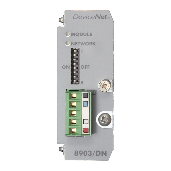
8903/DN
DeviceNet
Communications Option
Technical Manual
HA469264U001 Issue 3
© Copyright 2010 Parker Hannifin Ltd.
All rights strictly reserved. No part of this document may be stored in a retrieval system, or transmitted in any
form or by any means to persons not employed by a Parker Hannifin Ltd., Automation Group, SSD Drives
Europe without written permission from Parker Hannifin Ltd., Automation Group, SSD Drives Europe. Although
every effort has been taken to ensure the accuracy of this document it may be necessary, without notice, to
make amendments or correct omissions. Parker Hannifin ltd., Automation Group, SSD Drives Europe cannot
accept responsibility for damage, injury, or expenses resulting there from.
Parker Hannifin Ltd., Automation Group, SSD Drives Europe, warrants the goods against defects in design, materials
and workmanship for the period of 24 months from the date of manufacture, or 12 months from the date of delivery
(whichever is the longer period) on the terms detailed in Parker SSD Drives Standard Conditions of Sale IA500504.
Parker Hannifin Ltd., Automation Group, SSD Drives Europe reserves the right to change the content and product
WARRANTY
specification without notice.
Advertisement
Table of Contents

Subscribe to Our Youtube Channel
Related Manuals for Parker 8903/DN


Summary of Contents for Parker 8903/DN
- Page 1 All rights strictly reserved. No part of this document may be stored in a retrieval system, or transmitted in any form or by any means to persons not employed by a Parker Hannifin Ltd., Automation Group, SSD Drives Europe without written permission from Parker Hannifin Ltd., Automation Group, SSD Drives Europe. Although every effort has been taken to ensure the accuracy of this document it may be necessary, without notice, to make amendments or correct omissions.
- Page 2 Parker or its subsidiaries or authorized distributors. To the extent that Parker or its subsidiaries or authorized...
- Page 3 Safety Information Requirements IMPORTANT: Please read this information BEFORE installing the equipment. Intended Users This manual is to be made available to all persons who are required to install, configure or service equipment described herein, or any other associated operation. The information given is intended to highlight safety issues, EMC considerations, and to enable the user to obtain maximum benefit from the equipment.
- Page 4 Safety Information Hazards DANGER! - Ignoring the following may result in injury 1. This equipment can endanger life by exposure to 5. For measurements use only a meter to IEC 61010 rotating machinery and high voltages. (CAT III or higher). Always begin using the highest range.
-
Page 5: Table Of Contents
Contents Contents Page EVICE OMMUNICATIONS PTION Introduction ..................... 1 Product Features ......................1 Product Order Code....................1 Compatible Firmware....................1 Restrictions......................... 1 Installation....................... 2 Wiring the System.................... 5 Setting MAC ID and Baud Rate................ 7 Drive Diagnostics..................... 8 The DeviceNet MMI View .................... 8 •... -
Page 7: Device Net Communications Option
This option will work with the following version of 890 firmware: Version 1.9 onwards Version 2.4 onwards Version 3.1 onwards Version 4.1 onwards Restrictions Option must be fitted in Slot A. When 8903/DN is fitted, the options 8903/SP and 8903/CB cannot be used. DeviceNet Communications Interface... -
Page 8: Installation
Installation WARNING! Before installing, ensure that the drive wiring is electrically isolated and cannot be made “live” unintentionally by other personnel. Wait 5 minutes after disconnecting power before working on any part of the system or removing the covers from the drives. To Remove the Control Board 1. - Page 9 Fitting the Option The Option fits on to the Control Board. 1. Insert the connector into the Option as shown. The legs of the connector will protrude through into the connector on the other side of the Option. 2. Press the assembly into the TOP connector (adjacent to terminals X13, X14 and X15) on the Control Board.
- Page 10 Re-fitting the Control Board 1. Slide the board into the drive, engaging the edges of the boards into the slots. Push until the back edge of the Control Board PCB locates with the connectors in the drive. 2. Tighten in position using the top and bottom screws in the handles of the Control Board. 3.
-
Page 11: Wiring The System
Wiring the System DeviceNet is a 4-wire system. Two wires convey the DeviceNet data and the remaining two wires convey power if the product is remotely powered. Remote powering is recommended and is necessary if the network is to remain operational between other devices when the drive is powered down. - Page 12 Important: Failing to fit terminating resistors correctly may result in unreliable operation. For more information about cabling and terminators, refer to www.ODVA.org Terminal Block (X40) Connections 8903/DN Designation Wire Colour Pin Number Front View: black...
-
Page 13: Setting Mac Id And Baud Rate
The DIP switches allow you to select 6 bits for the MAC ID and 2 bits for Baud Rate. NOTE If all 8 bits are in the ON position, MAC ID and Baud Rate are set by software. If the DSE DeviceNet function block is instantiated then this has precedence over the MMI. 8903/DN Binary Function Example... -
Page 14: Drive Diagnostics
Drive Diagnostics The DeviceNet MMI View The following DeviceNet diagnostic parameters can be displayed on the MMI. Parameter Descriptions BAUDRATE Read only Range: Enumerated - see below The Baudrate set by either the DIP switches 7 and 8 on the front of the DeviceNet Option or set by the DNET block in the DSE configuration. - Page 15 Parameter Descriptions HARDWARE Read only Range: FALSE / TRUE Displays the method being used to set the node address and baudrate. If all the MAC ID and Baudrate Switches are set to ON, then the method is set by the DSE configuration, otherwise it is by hardware i.e.
-
Page 16: Configuring The Devicenet System
Configuring the DeviceNet System To configure the DeviceNet system, complete the steps below: Step 1: Configuring the DeviceNet Option using DSE Step 1.1: Inserting a DeviceNet Function Block Display your configuration page. Click on the Block menu at the top of the screen. 1. -
Page 17: Step 1.2: Attaching Fieldbus Connectors
Step 1.2: Attaching Fieldbus Connectors Seven feldbus connector types are available: FB Logic Input FB Integer Input FB Value Input FB Logic Output FB Integer Output FB Value Output FB Val to Int Output Input connector : the data is sent from PLC → 890 Output connector : the data is sent from 890 →... -
Page 18: Step 1.3: Configuring The Fieldbus Connectors
Step 1.3: Configuring the Fieldbus Connectors Double-click on the function block to display the dialog below. The fieldbus connectors (inputs and outputs) are assignable in the function block along with their data type to/from the PLC. The Baudrate and MAC Id can also be selected. An Input may be configured to be either Polled or Explicit. -
Page 19: Dse Data Types
3. Click in the Type field to choose the required PLC type on Register 1, for example. 4. Set up all the input/output registers in a similar way. 5. Right click on a row to insert, move or delete a register. 6. -
Page 20: Devicenet Status Information
DeviceNet Status Information The DeviceNet function block in DSE provides status information about the DeviceNet network interface. When online, the actual MAC Id in use can be found by clicking the right mouse button over the “MAC Id:” text and selecting Get. This may be different to the MAC Id set in the function block configuration if the switches on the Option have set the Address. -
Page 21: Step 2: Configuring The Plc/Scada Supervisor
The 890 is added into the Generic category. 2. Select with the mouse and drag across to the network window, then click on new node to set the required MAC Id. Parker SSD Drives DeviceNet Communications Interface... - Page 22 Make a connection between the scanner and the drive. Double click on the icon for the scanner node: Now click on the Scanlist tab: DeviceNet Communications Interface...
- Page 23 The left-hand window shows a list of devices which can be connected. The right-hand window shows a list of devices currently connected. To connect the 890 drive at at address 05, select it, as shown, and then click The 890 drive moves to the right-hand window: Now click on Edit I/O Parameters to specify the number of bytes to be transferred: DeviceNet Communications Interface...
- Page 24 The default configuration specified in the EDS file selects Polled I/O with 8 Input bytes and 5 Output bytes. This needs to be change to what is required. For example, if Polled I/O is required with just 2 Output bytes, then enter as below: Click OK.
- Page 25 Click OK. 4. Download the completed configuration into the PLC, ensure that the PLC is in the PROG mode. For example, the SLC-500 has a keyswitch to select this. Then go online to the DeviceNet network by clicking the Online button: The system will scan the online network and add a status flag against each device as appropriate.
-
Page 26: Polled Inputs And Outputs
Polled Inputs and Outputs The Poll command is a message that is transmitted by the Master. It is directed towards a single, specific Slave (point-to-point connection). A master must transmit a separate Poll message for each one of its Slaves that are to be polled. The Poll-Response is an I/O message that the Slave transmits back to the master when the Poll Command is received. - Page 27 If the DSE configuration does not contain a DNET function block, the Assembly Object defaults are: Polled Inputs, size 5 bytes Byte Parameter Data Format 0, 1, 2, 3 REFERENCE::REMOTE SETPOINT IEEE-754 32-bit floating point (PREF 101.01) REFERENCE::REVERSE 0x00 = FALSE, 0x01 = TRUE (PREF 101.11) Polled Outputs, size 8 bytes Byte...
-
Page 28: Change Of State (Cos) And Cyclic Outputs
Change Of State (COS) and Cyclic Outputs A device only sends a Change of State (COS) / Cyclic Output message when either data has changed or after a pre-defined timer expiry (heartbeat). Both the mode and cycle time are defined by the PLC. The 890 supports a single Assembly Object for COS / Cyclic Output. -
Page 29: Explicit Messaging
Explicit Messaging Through explicit messaging, the DeviceNet option provides the ability to access parameters within the 890 drive. Explicit messages are identified by a class number, instance number and attribute number. The Write and Read access is possible with the DeviceNet Common services: Get_Attribute_Single ( Read) Set_Attribute_Single (Write) Two vendor specific class, 0x64 and 0x65, are provided to allow access to 890 fixed parameters... -
Page 30: User Defined Register Set Object
Attribute is the same as the Parameter Number. For example, REFERENCE::REMOTE SETPOINT has PREF 101.01, so Instance is 100 (0x64) and Attribute is 1. The Data Format for this object is fixed as follows: Data Type Data Format PLC Size BOOL 0x00 = FALSE, 0x01 = TRUE 1 byte... -
Page 31: Identity Object
Identity Object Class 0x01, Instance 0x01 Attribute Attribute Name Attribute Value Description Number VENDOR ID 0x0261 (609) PARKER SSD DRIVES Vendor ID managed by the ODVA DEVICE TYPE 0x0000 GENERIC DEVICE PRODUCT CODE 0x8903 890 DeviceNet Product number MAJOR Major Revision Number... -
Page 32: Appendix A : Troubleshooting
Appendix A : Troubleshooting 890 DeviceNet Option Status LEDs At power-on, the first action is an LED Test for both LED’s: Green ON Red ON Green ON Colour LED Indication Description MODULE LED No Power Device operational GREEN FLASH Device in Stand by GREEN/OFF Unrecoverable Fault FLASH... -
Page 33: Appendix B : Dse/Devicenet Conversion Rules
Appendix B : DSE/DeviceNet Conversion Rules The rules governing the conversion between 890 data types and DeviceNet PLC data types are given below. Note carefully that some conversions will result in rounding, limiting and truncation of the original value. LOGIC Type Connector Data from PLC Data to 890 False... -
Page 34: Integer Type Connector
INTEGER Type Connector Data from PLC Data to 890 From BOOL to INTEGER False 0x0000 0000 True 0x0000 0001 From SINT to INTEGER -128 to 127 -128 to 127 -32,768 to 32,767 -32,768 to 32,767 From INT to INTEGER From DINT to INTEGER -2,147,483,648 to -2,147,483,648 to 2,147,483,547... -
Page 35: Value Type Connector
VALUE Type Connector Data from PLC Data to 890 From BOOL to VALUE False True -128 to 127 -128.0 to 127.0 From SINT to VALUE From INT to VALUE -32,768 to 32,767 -32,768.0 to 32,767.0 From DINT to VALUE -2,147,483,648 to -32,768.0 to 32,767.0 2,147,483,547 limits apply... - Page 36 ISS. MODIFICATION ECN No. DATE DRAWN CHK'D Initial Issue (HA469264U001) 17320 21/03/06 Company name change. DSE configuration added. 19591 14/03/07 Updated Warranty information and conditions of sale. (20358) Photos and screenshots updated. Standardised Safety pages over 3 pages. Product Code – added new coding. Replaced TechCard with Option and Replaced DSE 890 with DSE.
Need help?
Do you have a question about the 8903/DN and is the answer not in the manual?
Questions and answers