
Summary of Contents for SMG Powerlight 612
- Page 1 Powerlight 612 P r o f e s s i o n a l D i m m e r User’s Manual rel. 1.03...
-
Page 2: General Instructions
General instructions Read the instructions in this handbook carefully, as they give important information regarding safety during installation, use and maintenance. Be sure to keep this instruction manual with the unit, in order to consult it in the future. If the unit is sold or given to another operator, make certain that it always has its manual, to enable the new owner to read about its operation and relative instructions •... -
Page 3: How To Contact Sgm Elettronica
General warranty conditions • The unit is guaranteed for 12 months from the date of purchase against material and manufacturing defects. • Breakdown caused by carelessness and improper use of the unit is excluded. • The guarantee is no longer valid if the unit has been tampered with or repaired by unauthorized personnel. -
Page 4: Table Of Contents
Index General Instructions General guarantee conditions How to contact SGM Elettronica Index Introduction 1 - Main features 1.1 - Technical specifications 1.2 - Installation 1.2.1 - Packaging 1.2.2 - Contents 1.2.3 - Before installation 1.3 - P612 connections 1.3.1 - Connecting to the mains supply 1.3.2 - Rear panels 1.3.3 - DMX signal cable 1.3.4 - DMX line connection example... -
Page 5: Introduction
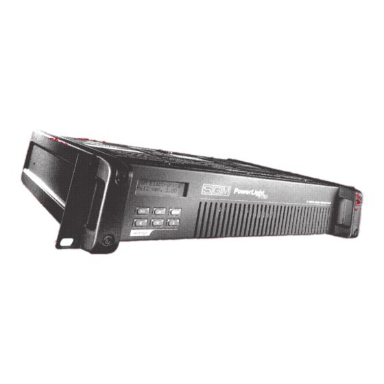
Introduction Power Light P612 is a new digital dimmer entirely designed and developed by SGM's Research & Development Department. Careful study of its functions, selection of innovative material and on- going technical updates have resulted in the manufacture of a truly unique product, able to satisfy the requirements of applications in the live sector and well as fixed installations. -
Page 6: Main Features
1. Main features • Power supply: three phase 380V 3 PHASES + NEUTRAL, or single phase 110 - 220 V. Mains frequency 50/60 Hz. The power supply for the electronics' logic part is taken from the T phase + NEUTRAL. •... -
Page 7: Installation
1.2 Installation 1.2.1 Packaging KEEP THE PACKAGING MATERIAL. Packaging material (plastic bags, polystyrene foam, nails, etc.) must not be left within children's reach, as it can be dangerous. Use the original packaging if the unit has to be returned to the manufacturer for repair or maintenance, as it has been specifically design to protect the unit during transport. -
Page 8: Rear Panels
1.3 Connection the P612 1.3.1 Connecting the power supply • It must be connected to a circuit with a thermal-magnetic cut-off switch.(see appendix page 1, 2, 3) • Make certain that the cross-section of the socket's cables is sufficient for the power absorbed by the unit. -
Page 9: Dmx Signal Cable
1.3.3 DMX signal cable construction Power Light P612 has a DMX 512 input that uses standard XLR 5-pin connectors. When connecting, screened cable in compliance with EIA RS-485 specifications and with the following characteristics must be used: - 2 conductors plus screen - 120 Ohm impedance - low capacity - maximum transmission rate 250Kbaud. -
Page 10: Dmx Termination Construction
1.3.5 DMX termination construction The termination avoids the possibility of the DMX 512 signal being sent back along the cable once it reaches the end: under certain conditions and with certain lengths, this could cause it to over-ride the original signal and cancel it. The termination is made by soldering a 120 1/4 W resistor across pins 2 and 3 of the 5-pole male XLR connector (see diagram). -
Page 11: Switching On
1.3.7 Switching on As soon as it's switched on, the Power Light P612 display the SGM logo with the software version, after which it begins an autotest (self test) routine to check for any irregularities in the power supply and on the output. Press ENTER to proceed to the Main Menu. -
Page 12: Soft Patch
2 - Menu descriptions 2.1 Soft Patch In this Menu, it's possible to assign the POWER LIGHT's physical channels (CHN) to the digital channels available (ADDR). This creates a correspondence between the Dimmer output channel and the channel that has to be controlled. There are 512 channels available for use, i.e., those provided for by DMX standard, and they don't necessarily have to be in succession. -
Page 13: Set Chn Level
has to be assigned; 4. Now move the square brackets to the MOD field to assign one of the three operating modes available; [FIX] 5. Repeat from point 3 to set the other channels. 6. Press Esc to return to the main menu: 2.3 Set Chn Level (Channel Level) In this Menu it's possible to set the level of each individual channel configured in FIX mode in the previous menu. -
Page 14: Channel Test
For access to the Set Pre Heat function, proceed as follows: 1. Select the Set Pre Heat menu from the main menu; <Main Menu > [Set pre heat 2. Press Enter to confirm the choice; 3. Move the square brackets to the CHN field and select the channel whose pre-heat level has to be set;... -
Page 15: Brightness
2.6 Brightness In this Menu, it's possible to vary the brightness of the LCD display on the front panel. This brightness is expressed as a percentage and varies between 0 and 100%. The standard factory setting of the LCD brightness is 75% For access to the Brightness function , proceed as follows: 1. -
Page 16: Version
For access to this function, proceed as follows: 1. Select the VPHASE MONITOR menu from the main menu; <Main Menu > [Vphase monitor] 2. Press ENTER to confirm the choice; 3. The square brackets will be positioned on the PHASE field to allow the required phase to be selected 4. -
Page 17: Set Voltage
1. Select the Autotest Run menu from the main menu; <Main Menu > [Version 2. Press Enter to confirm the choice; 3. A this point, the results of the measurements made for all the abovementioned parameters will appear one after another on the display. AUTOTESTING [OVERLOAD 4. -
Page 18: Run Chase
2. Press ENTER to confirm the choice; 3. Now select the number of the Chase to be programmed, which can be between 1 and 8 <Edit chase > Chase 4. Press ENTER to confirm the choice; 5. At this point, the following appears on the display: ST CHN [10] Maximum number of steps... - Page 19 2.14 Curve Equaliz (Curve Equalization) In this menu, it's possible to assign each channel the most suitable setting for controlling the load on output according to the type of lamp used. The 6 curves available are shown in the diagram. For access to the Curve Equal function, proceed as follows: 1.
-
Page 20: Protections
3 - Protections Particular protections are provided to avoid any faulty operation seriously damaging the Power Light. These protections are: 3.1 - OVER-HEATING PROTECTION: the maximum temperature allowed is 90ºC and is measured on the cooling fin on the power section. If this temperature is exceeded, the output is disabled until temperature returns within the foreseen limits. - Page 21 M 001225 SGM Elettronica srl Via Pio La Torre, 1 • 61010 Tavullia (PS), Italy Tel. +39 0721 476477 • Fax +39 0721 476170 e-mail: info@sgm.it • http://www.sgm.it...
Need help?
Do you have a question about the Powerlight 612 and is the answer not in the manual?
Questions and answers