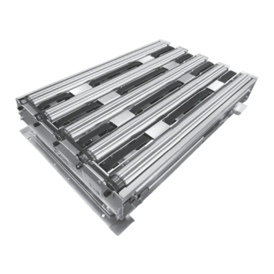
ITOH DENKI F-RAT-S300 User Manual
Flat right angle transfer unit
Hide thumbs
Also See for F-RAT-S300:
- User manual (16 pages) ,
- User manual (16 pages) ,
- Operating instructions manual (25 pages)
Table of Contents
Advertisement
Quick Links
F-RAT-S300
F-RAT-S300
Thank you for purchasing Flat Right Angle Transfer unit.
● Before using the product, carefully read this manual and retain it for future reference.
● Make sure whether the product you received complies to your purchased order, with its
designation, specification and operating voltage.
● Photo and drawing on this manual is Size B for explanations.
1.
2.
3.
4.
5.
6.
7.
8.
Appendix1.
Appendix2.
Flat-Right Angle Transfer
INDEX
Important safeguards
・・・・・・・・・・・
Product designation
・・・・・・・・・・・・
Structure
・・・・・・・・・・・・・・・・・・
Power supply
・・・・・・・・・・・・・・・
Dimensions
・・・・・・・・・・・・・・・・
Installation and Operation
Maintenance
・・・・・・・・・・・・・・・・
Product specification
・・・・・・・・・・・
CBR-305F□ Detail
Remaining Risks List/MAP
ITOH DENKI CO.,LTD.
User Manual
P1
P2
P2
P2
P3 ∼ P5
P5 ∼ P10
・・・・・・・・・
P11 ∼ P14
P15 ∼ P16
P17 ∼ P18
・・・・・・・
P19
・・・
No.474
Advertisement
Table of Contents

Related Manuals for ITOH DENKI F-RAT-S300


Summary of Contents for ITOH DENKI F-RAT-S300
- Page 1 ・・・・・・・・・・・・・・・ Dimensions P3 ∼ P5 ・・・・・・・・・・・・・・・・ Installation and Operation P5 ∼ P10 ・・・・・・・・・ Maintenance P11 ∼ P14 ・・・・・・・・・・・・・・・・ Product specification P15 ∼ P16 ・・・・・・・・・・・ CBR-305F□ Detail Appendix1. P17 ∼ P18 ・・・・・・・ Remaining Risks List/MAP Appendix2. ・・・ ITOH DENKI CO.,LTD. No.474...
- Page 2 . General Cautions …… For your safety, please comply with them. Be sure to comply with all of the caution items and instructions contained in this safety manual. ● To avoid functional deterioration, unexpected accident or product failure, check the operation according to this manual. ●...
-
Page 3: Product Designation
Accessories ⑥ Max load weight ■ ⑦ ⑧ ⑨ ⑩ SERIAL No. ⑦ ⑧ ⑨ Serial NO; YY/MM/DD ITOH DENKI CO.,LTD F-RAT mounting hardware ● ⑩ Lot No MADE IN JAPAN ・ 4 sets of M8-20 bolt / M8 nut Standard driver card : ●... - Page 4 5. Dimensions F-RAT ■ ● SIZE A … W379mm×L758mm (Mounting hole pitch) ● SIZE B … W497mm×L758mm (Mounting hole pitch) - 3 -...
- Page 5 ● SIZE C … W597mm×L758mm (Mounting hole pitch) ● SIZE D … W697mm×L758mm (Mounting hole pitch) - 4 -...
- Page 6 Accessory ■ ● CB-016□ ● CBR-305F□-B * □=N(NPN input / output) or P(PNP input / output) * □=N(NPN input / output) or P(PNP input / output) CB-016□ CBR-305F□-B 5.PLS 5.PLS SPEED SPEED M3 : 昇降用 4.ERR 4.ERR 3.V-IN 3.V-IN 2.DIR 2.DIR 1.RUN 1.RUN...
- Page 7 Checking the Wiring ● When the DC power supply is integrated, check if the equipment breaker and emergency stop switch correctly operate. ・ Test operation and any further procedure should be performed after finishing this checking. ① ON/OFF operation of the breaker reliably turns ON/OFF of the input (single phase 100V, 200V) to the DC power supply unit. ②...
- Page 8 Installation ■ ● F-RAT-S installation Mounting ・Use assistance and recheck the installation precaution before starting the installation. ・Firmly mount the product in consideration of product weight, load weight and vibration. ● Reference example for the mounting: In case of using a mounting stay (option), (Frame height is 160mm). Use mounting holes for F-RAT-S installation, Caution ●...
- Page 9 Wiring diagram ■ Output Input RUN signal In-coming MDR for signal belt CB-016□ Input/Output type for F-RAT-S : NPN Input/Output type for F-RAT-S : PNP transfer CB-016N, CBR-305FN-B wiring CB-016P, CBR-305FP-B wiring RUN signal Proximity sensor SN・S CBR-305F□ MDR for DIR signal belt transfer lifting...
- Page 10 F-RAT-S control ■ Rotation Direction Setting MDR for roller transfer (M2) S W 1 # 3 V-IN connected V-IN Connected ・MDR rotation (F-RAT transfer) direction can be changed by using the switch on the driver card or external switch. M1:Belt transfer direction (Or can be used in parallel) ・MDR rotation direction is defined as CW or clockwise direction *...
- Page 11 6 - 5.Precautions for Trial Run Checking the environment for permitting trial run ● Make sure other devices in the system do not run. ● In the case of a conveyor line integrated in a system, starting signal would cause a tray to flow down the conveyor and cause danger.
-
Page 12: Maintenance
7. Maintenance Precautions for Maintenance and Inspection Safety check before maintenance and inspection ● In order to avoid interference by power circuit and signals, turn off the power of all connected devices. ● Warning (a)After turning off the power switch, leave for more than 3 minutes for discharging the DC power supply. Indicate warning to prevent other people from turning the power. - Page 13 Transfer belt replacement ■ 《Replacement procedure》 Remove idlers for roller transfer adjoining the replaced transfer belt. (Refer to Transfer MDR replacement, P11.) ① Loosen the screws for the belt cover, and then remove the belt cover. ② Loosen the screws for idler wheel that is for belt tension adjustment. (Do not remove the screws). ③...
- Page 14 Checking Position of tension for transfer belt 《With push-pull gauge》 《With belt tension meter》 V-ribbed belt side V-ribbed belt side Size V-ribbed belt side V-ribbed belt side Size V-ribbed belt side V-ribbed belt side Size V-ribbed belt side V-ribbed belt side Size 108mm 117mm...
- Page 15 Belt transfer MDR replacement ■ 《Replacement procedure》 *Before replacing please turn off F-RAT-S and remove the motor cable of each MDR from the driver card. ① Remove the MDR and all idlers. (Refer to Transfer MDR replacement , P11.) MDR for belt transfer MDR for roller transfer and idlers for transfer ①...
-
Page 16: Product Specification
8. Product specification Product specification ■CB-016□/ CBR-305F□-B ■F-RAT-S * □ = N (NPN) or P (PNP) Roller Diameter Power voltage 24VDC±10% φ50mm Rated voltage 24VDC Width (W) Roller transfer direction 379mm, 497mm, 597mm, 697mm Size Static current 0.03A Length (L) Belt transfer direction 758mm Starting current Height... - Page 17 ■ Replacement parts for F-RAT-S Transfer belt ① ・Flat belt : TF10 L1630 W19 V-ribbed belt ② ・3PJ336 (For pitch 100mm) ・3PJ316 (For pitch 94mm) For size A * MDR for belt transfer ③ ・For size A・PM500FE- speed code-277-D-024-JG-C150 * ・For size B・PM500FE- speed code-392-D-024-JG-C150 *...
-
Page 18: Appendix 1 . Cbr-305F □ Detail
Appendix 1 . CBR-305F □ Detail CBR-305 is a dedicated driver for up/down motion. MDR is driven by RUN signal input, M3:Lifting driver card has been set by the factory. Caution but is automatically stopped after counting Do not change. Change may lead to a failure. predetermined motor pulses. - Page 19 ■ Rotation Direction Change ・MDR rotation can be changed by external switch. S W 1 # 3 V-IN CW/CCW ※MDR rotation in the right turn direction is defined as CW when connected viewed from the cable side, and left turn as CCW. ※0V must be common to the power supply.
-
Page 20: Appendix 2 . Remaining Risks List, Map
Warning No.3 No.8 http://www.itohdenki.co.jp Europe, Middle East, Africa: Itoh Denki Europe SAS Asia/Oceania: Itoh Denki Asia Limited Headquarters: Itoh Denki Co.,Ltd. Phone: +33 (0)4 50 03 09 99 Fax: +33 (0)4 50 03 07 60 Phone: +852 2427 2576 Fax: +852 2427 2203 Phone: +81 (0)790 47 0955 Fax: +81 (0)790 47 1325 www.itoh-denki.com...
Need help?
Do you have a question about the F-RAT-S300 and is the answer not in the manual?
Questions and answers