Table of Contents
Advertisement
Quick Links
Advertisement
Table of Contents

Summary of Contents for Neoway N10
- Page 1 N10 Demo Board User Guide Version 1.0...
- Page 2 Shenzhen Neoway provides customers complete technical support. If you have any question, please contact your account manager or email to the following email addresses: Sales@neoway.com...
- Page 3 N10 Demo Board User Guide Revision Record Issue Changes Date V1.0 Initial draft 2017-02 Copyright © Neoway Technology Co., Ltd...
-
Page 4: Table Of Contents
N10 Demo Board User Guide Content 1 Overview ..........................1 2 N10 Description of Interfaces ..................1 3 N10 Development board interfaces ................2 3.1 N10 Development board ........................2 3.2 Power and Serial port development board ..................3 3.2.1 5V/2A power adapter ........................ 3 3.2.2 M5X0-PWR serial port board .................... -
Page 5: Overview
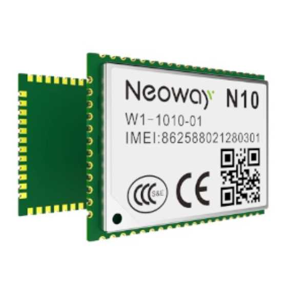
N10 Demo Board User Guide 1 Overview N10 Development board is used to debug hardware and software. It provides a series of peripheral interfaces including main power supply, UART interfaces, SIM card, antenna, ON/OFF control and USB interface. All relevant debugging can be carried out on condition that power supply and UART interface are connected. -
Page 6: N10 Development Board Interfaces
N10 Demo Board User Guide 3 N10 Development board interfaces 3.1 N10 Development board Front side Back side Copyright © Neoway Technology Co., Ltd... -
Page 7: Power And Serial Port Development Board
10、SIM card interface. 3.2 Power and Serial port development board N10 development board supports two ways of power supply: Way 1 Use the M5X0-PWR serial port board, through the serial port 1 it can supply 3.9V voltage to the module;... -
Page 8: M5X0-Pwr Serial Port Board
N10 Demo Board User Guide 3.2.2 M5X0-PWR serial port board The above picture is the M5X0-PWR serial port board, the main function is supply power to the module via computer USB interface with the voltage of 3.8V / 0.6A, and through the USB to serial chip output 3.3V COMS logic level, TXD / RXD achieve computer and module to communicate. -
Page 9: Product Debugging
N10 Demo Board User Guide 3.3 Product debugging Product debugging through the serial port do debugging, details operation as following: 3.3.1 Serial port debugging through serial port power supply For serial port debugging, you need to install the serial port driver (PL2303). After driver is Installed, after inserting the M5X0-PWR board, the device manager port (COM and LPT) shows”... -
Page 10: Serial Port Debugging, With Dc Power Supply
N10 Demo Board User Guide 3.3.2 Serial port debugging, with DC power supply Through DC power supply connection method is as shown below picture, while move power switch away from the 5V DC power supply side, and disconnect jumper connection, then, it can supply power to the module. -
Page 11: Availabel List Of Accessories
N10 Demo Board User Guide Serial port print information: 4 Availabel list of accessories N10 Demo board (Including Moudle) M5X0-PWR serial port board Others (5V / 2A power adaptor, GPRS antenna, etc.)) Copyright © Neoway Technology Co., Ltd...


Need help?
Do you have a question about the N10 and is the answer not in the manual?
Questions and answers