Table of Contents
Advertisement
Available languages
Available languages
Quick Links
SERVICE MANUAL
EN
II2G
Temperature range:
Order number
Inlet
Female
HGBR - 609
DESCRIPTION
The fluid pressure relief valve can be used
in 2 functions:
• In « circulating » system as a back
pressure valve to maintain system
and maintain material fluid flow
when no material is being used.
• As by-pass valve to protect against
excessive line pressure, the result of
either material flow exceeding valve
capacity or the result of a restriction
in the line beyond the by pass valve.)
SB-6-HGBR-R1 (3/2018)
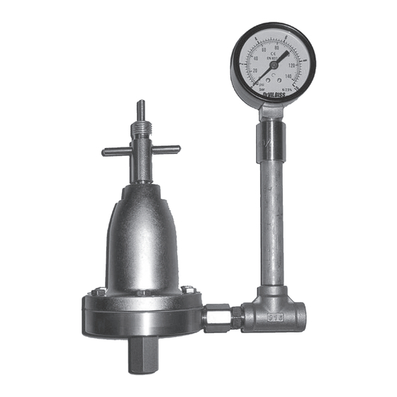
HGBR-609 FLUID REGULATOR
0° – 50°C (32° – 122°F)
Thread
Outlet
Female
1/4
1/4
SPECIFICATIONS
The fluid passages of this Fluid Pressure
Relief Valve are in stainless steel (303).
This HGBR regulator is equipped with a
manual spring adjusting pressure system.
The manometer is fitted on a riser tube and
tee connection in stainless steel material.
This HGBR regulator is suitable for use
with halogenated hydrocarbons and user
must ensure that all other equipment in
the system is also suitable for use with this
material.
A Manual Adjustment Key
B Spring
C Diaphragm Assembly
D Valve stem
Inlet pressure
Outlet pressure
min-max.bar
max.bar
2 / 12,5
0 / 9
1 / 6
E
Fluid outlet
F
Fluid Inlet
G Riser tube
H Manometer
Fluid flow
Manometer
maximum
L/min
18
IMPORTANT: This Fluid Pressure Relief
Valve may be used with most common
coating and finishing material. However,
they are not designed for use with highly
corrosive or highly abrasive materials.
If used with materials which have such
characteristics,
it
must
be
that frequent and thorough cleaning
will be required and/or the necessity for
replacement of parts will be increased.
If there is any doubt about the suitability
of the HGBR for a particular material,
inform your local DeVilbiss distributor
what material is to be used, or submit a
sample of such material for test.
www.carlisleft.com
bar
0 – 10
expected
Advertisement
Table of Contents

Subscribe to Our Youtube Channel
Related Manuals for Binks HGBR-609


Summary of Contents for Binks HGBR-609
- Page 1 SERVICE MANUAL II2G HGBR-609 FLUID REGULATOR A Manual Adjustment Key Fluid outlet B Spring Fluid Inlet C Diaphragm Assembly G Riser tube D Valve stem H Manometer Temperature range: 0° – 50°C (32° – 122°F) Thread Fluid flow Inlet pressure...
-
Page 2: Eu Declaration Of Conformity
Product Description/Object of Declaration: Fluid Regulators - HGB-509, HGB-510, HGB-609, HGBR- This Product is designed for use with: Solvent and Water based Materials Suitable for use in hazardous area: Zone 1 Protection Level: II 2 G Notified body details and role: Element Materials Technology. - Page 3 The removal of waste solvents and coating earth continuity to all equipment should be maintained. materials should be carried out by an authorized local The fluid back regulator HGBR-609 has stainless steel waste disposal service. body and fluid connectors. Check earth continuity with...
- Page 4 TYPICAL INSTALLATION IN CIRCULATING SYSTEM Description Oil and moisture separator Air hose Supply tank Pump Standpipe Filter Three way valve Material filter Fluid pressure gauge Fluid pressure regulator HGB to supply material at the spray gun Fluid pressure relief valve in the back fluid pressure regulation application Fluid pressure relief valve...
-
Page 5: Parts List
PARTS LIST Order Order Number Description Qty. Number Description Qty. HGB-404-1 Adjusting key HGBR-426 Kit of Fluid inlet F1/4" BSP HGB-28 Cover HGB-62 PTFE Gasket S-1309-H Screw M5 * 16mm for HGBR 609 Coupling Stainless Steel 1/4‘’ BSP HGB-82 male x 7/16‘’ male HGB-408-H Adjusting screw assembly Tee Stainless Steel 1/4‘’... -
Page 6: Replacement Of Parts
REPLACEMENT OF PARTS Before dismantling valve switch off the material pump and relieve pressure in the system. TO REPLACE DIAPHRAGM (Rep. 7) TO SERVICE VALVE ASSEMBLY (Rep. 12) 1. Unscrew the 6 hex. head cap screws. 1. Unscrew the fluid outlet valve from the regulator body. 2. -
Page 7: Especificaciones
MANUAL DE SERVICIO II2G REGULADOR DE FLUIDO HGBR-609 A Clave de regulación manual Salida del fluido B Muelle de membrana Entrada del fluido C Membrana fluido G Tubo per realce H Manómetro Rango de temperaturas: 0° – 50°C (32° – 122°F) Roscado Presión de... -
Page 8: Declaración De Conformidad Eu
Descripción del producto / Objeto de la Declaración : Este Producto está diseñado para su uso Materiales de base de agua y disolventes con: Adecuado para su uso en áreas peligrosas: Zona 1 Nivel de protección: II 2 G Notificado de carrocería y papel : Element Materials Technology. - Page 9 El regulador de fluido de cortar las entradas de producto y aire. retorno HGBR-609 tiene un cuerpo y de las conexiones de acero inoxidable. Controlar la continuidad de la conexión Se debe proceder al desecho de solventes o productos directa a masa con un ohmiómetro.
-
Page 10: Instalación
PLAN DE NORMA DE LA UTILIZACIÓN Descripción Depurador de aire Tubo de aire Deposito del fluido Bomba Sumidero de bomba Filtro Llave con 3 vías Filtro de fluido Manómetro de fluido Regulador de fluido HGB alimentación a la pistola Regulador de retorno sobre la línea de retorno del fluido hacia Regulador de retorno como... -
Page 11: Lista De Componentes
Tapadera del regulador de HGB-28 retorno HGB-62 Junta de PTFE S-1309-H Para HGBR-609, Tornillo M5 * 16 Manguito de acero inoxidable HGB-82 1/4’’BSP macho x 7/16‘’ macho HGB-408-H Tornillo de ajuste Te de acero inoxidable 1/4‘’ BSP... -
Page 12: Sustitución De Componentes
SUSTITUCIÓN DE COMPONENTES Para la bomba y bajar la presión antes del mantenimiento del regulador. SUSTITUCIÓN DE LA MEMBRANA (Nº 7) DESMONTAJE DEL KIT DE VÁLVULA (N°12) 1. Retirar los seis tornillos y quitar la tapadera. 1. Desenroscar la conexión de entrada del fluido y el soporte de junta. -
Page 13: Manuel De Service
MANUEL DE SERVICE II2G RÉGULATEUR DE RETOUR PRODUIT HGBR-609 A Clé de réglage manuel Sortie produit B Ressort Entrée produit C Ensemble membrane G Tube de rehausse D Clapet H Manomètre Échelle de températures: 0° – 50°C (32° – 122°F) -
Page 14: Déclaration De Conformité Eu
Description / objet de la Déclaration de produit: Ce produit a été conçu pour être utilisé Matériaux à base de solvant et d'eau avec : Approprié pour une utilisation dans des Zones 1 zones dangereuses : Niveau de protection : II 2 G Notifiée de carrosserie et le rôle : Element Materials Technology. -
Page 15: Consignes De Securite
CONSIGNES DE SECURITE Important : Lire soigneusement, suivre les instructions et les mesures de précautions avant de mettre en marche l’équipement. L’employeur est chargé de mettre ces informations à la disposition de l’opérateur. FEU ET EXPLOSION pulvérise. Le type d’équipement de protection doit être compatible avec le produit pulvérisé... - Page 16 TYPICAL INSTALLATION IN CIRCULATING SYSTEM Description Epurateur d’air Tuyau d’air Réservoir de produit Pompe Puisard de pompe Filtre Robinet 3 voies Filtre de produit Manomètre produit Régulateur de produit HGB alimentation au pistolet Régulateur de retour sur ligne produit retour au réservoir Régulateur de retour en K’...
- Page 17 Kit F1/4" Gaz pour sortie HGBR-426 régulateur HGB-28 Coiffe du régulateur de retour HGB-62 Joint PTFE S-1309-H Vis M5 * 16 mm pour HGBR-609 Mamelon acier inoxydable HGB-408-H Ensemble vis de réglage HGB-82 1/4‘’ BSP mâle x 7/16‘’ mâle HGB-7 Ecrou de réglage Té...
- Page 18 REMPLACEMENT DES PIÈCES DÉTACHÉES Arrêter la pompe et faire chuter la pression avant toute intervention d’entretien sur le régulateur. REMPLACEMENT DU DIAPHRAGME (Rep 7) DEMONTAGE DE L'ENSEMBLE VALVE (Rep 12) 1. Dévisser les six vis et ôter la coiffe. 1. Dévisser le raccord de sortie produit avec le support de joint. 2.
- Page 19 SERVICE-HANDBUCH II2G DURCHFLUSSREGLER HGBR-609 A Stellschlüssel Produktaustritt B Feder Produkteintritt C Membransatz G Aufsatzrohr D Ventil H Manometer Temperaturbereich: 0° – 50°C (32° – 122°F) Anschluss Max. Manometer- Eintritts-druck Austritts-druck Artikelnr Ausbringmenge skala min-max.bar max.bar Produkteintritt Produktaustritt L/min Innengewinde Innengewinde...
-
Page 20: Eu-Konformitätserklärung
Produktbeschreibung / Objekt der Erklärung : Dieses Produkt wurde entwickelt zur Wasser- und lösungsmittelhaltige Materialien Verwendung mit: Für den Einsatz in explosionsgefährdeten Zone 1 Bereichen geeignet Schutzniveau: II 2 G Benannte Stelle Details und Rolle : Element Materials Technology. WN8 9PN UK Unterkünfte für Technische Datei Diese Konformitätserklärung / Carlisle Fluid Technologies,... -
Page 21: Unsachgemäßer Gebrauch
SICHERHEITSHINWEISE Wichtig: Bitte lesen Sie vor der Inbetriebnahme der Anlage sorgfältig die nachstehenden Hinweise und befolgen Sie die Anweisun- gen und Vorsichtsmaßnahmen. Der Arbeitgeber ist verpflichtet, seinem Bedienungspersonal diese Hinweise zur Verfügung zu stellen. BRAND- UND EXPLOSIONSSCHUTZ Der Einsatz von Schutzausrüstungen für die Atemwege wird für jeden Sprühvorgang empfohlen. -
Page 22: Bedienung
BENUTZUNGSPLAN Artikelbezeichnung Luftreinigungsvorrichtung Luftrohr Produktbehälter Pumpe Pumpensickerschacht Filter Dreiweghahn Produktfilter Produkt-Manometer Produktregler HGB- Pistolenspeiseregler Rückregler für die Produktrückförderung zum Tank Rückregler als K’ Sicherheitsventil Absperrventil INSTALLATION Verschmutzungen oder Späne auf AUßENSEITE REGLERS dem Ventilsitz des Reglers ablagern. REGELMÄßIG EINEM Gebrauch des Rückreglers: Wird der Es wird die VERWENDUNG EINES LÖSUNGSMITTEL GETRÄNKTEN TUCH Regler als Rückregler benutzt, muss dieser... - Page 23 Satz F1/4 " Gas für Regleraustritt HGB-404-1 Stellschlüssel HGB-62 PTFEdichtung HGB-28 Reglerhaube 1/4’’ BSP x 7/16‘’ Muffe aus S-1309-H Schraube M5 * 16 Für HGBR-609 HGB-82 Edelstahl, Außengewinde/ HGB-408-H Stellschraube Außengewinde HGB-7 Stellmutter T-Stück aus Edelstahl 1/4’’ BSP – S-3006...
- Page 24 AUSTAUSCH VON ERSATZTEILEN Vor jeder Wartung die Pumpe und dadurch den Druck auf den Regler abschalten. AUSTAUSCH DES DIAPHRAGMAS (Rep 7) AUSBAU DES VENTILSATZES (Rep 12) 1. Die sechs Schrauben abschrauben und die Reglerkappe 1. Den Produktaustrittsstutzen Dichtungshalter entfernen. abschrauben. 2.
-
Page 25: Manuale Di Servizio
MANUALE DI SERVIZIO II2G REGOLATORI PRODOTTO HGBR-609 A Chiave per regolazione manuale Salida prodotto B Molla della membrana Entrata prodotto C Membrana prodotto G Tubo di rialzamento H Manometro Gamma temperatura: 0° – 50°C (32° – 122°F) Filettatura Pressione di... -
Page 26: Dichiarazione Di Conformità Eu
Descrizione del prodotto / Oggetto della dichiarazione : Il presente Prodotto è destinato all'uso Materiali a base solvente e acqua con: Adatto per l'uso in aree pericolose: Zona 1 Livello protezione: II 2 G Notificato dettagli del corpo e il ruolo : Element Materials Technology. - Page 27 Il regolatore di ritorno di prodotto HGBR-609 ha abilitato allo smaltimento di tali rifiuti. un corpo e dei raccordi prodotto in acciaio inox. Con un ohmmetro, verificare la continuità...
-
Page 28: Manutenzione Preventiva
SCHEMA DEI PRINCIPI PER L’USO Descrizione Depuratore d’aria Tubo d’aria Serbatoio per il prodotto Pompa Pozzo perdente della pompa Filtro Rubinetto 3 vie Filtro del prodotto Manometro del prodotto Regolatore del prodotto HGB per l’alimentazione alla pistola Regolatore di ritorno sulla linea del prodotto con ritorno al serbatoio Regolatore di ritorno... - Page 29 Kit di collegamento F1/4" Gas HGB-404-1 HGBR-426 per l’uscita del prodotto del regolatore HGB-28 Coperchio del regolatore S-1309-H Vite M5 * 16 mm per HGBR-609 HGB-62 Guarnizione PTFE HGB-408-H Vite di regolazione Manicotto in acciaio inox 1/4’’BSP HGB-82 HGB-7 Dado di regolazione Maschio x 7/16‘’...
- Page 30 CAMBIO DI PEZZI Fermare la pompa e fare cadere la pressione prima di tutta manutenzione sul regolatore. SOSTITUZIONE DELLA MEMBRANA (N° 7) SMONTAGGIO DEL KIT VALVOLA (N° 12) 1. Svitare le sei viti e togliere il coperchio. 1. Svitare il raccordo di entrata del prodotto con il supporto della guarnizione.
- Page 31 NOTES SB-6-HGBR-R1 (3/2018) 31 / 32 www.carlisleft.com...
-
Page 32: Warranty Policy
Carlisle Fluid Technologies is a global leader in innovative finishing technologies. Carlisle Fluid Technologies reserves the right to modify equipment specifications without prior notice. DeVilbiss , Ransburg , ms , BGK , and Binks ® ® ® ® ® are registered trademarks of Carlisle Fluid Technologies, Inc.
Need help?
Do you have a question about the HGBR-609 and is the answer not in the manual?
Questions and answers