Table of Contents

Related Manuals for Sunny SF-E2310


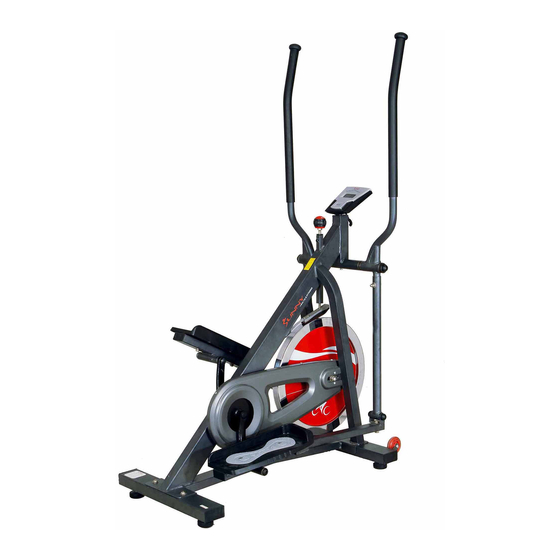
Summary of Contents for Sunny SF-E2310
-
Page 1: User Manual
FLYWHEEL ELLIPTICAL TRAINER SF-E2310 USER MANUAL IMPORTANT: Read all instructions carefully before using this product. Retain owner’s manual for future reference. For customer service, please contact: support@sunnyhealthfitness.com... -
Page 2: Important Safety Information
IMPORTANT SAFETY INFORMATION We thank you for choosing our product. To ensure your safety and health, please use this equipment correctly. It is important to read this entire manual before assembling and using the equipment. Safe and effective use can only be achieved if the equipment is assembled, maintained and used properly. -
Page 3: Exploded Drawing
EXPLODED DRAWING... -
Page 4: Parts List
PARTS LIST DESCRIPTION DESCRIPTION 1 Main frame 37 Left pedal 395*160*52 2 Front stabilizer 38 Right pedal 395*160*52 3 Rear stabilizer 39 Bolt M8*45*20*S14 grade A 4 Left handle bar 40 End cap J40*25*15 5 Right handle bar 41 End cap J60*30*15 42 Alloy wrap Φ28*4*φ24*12*Φ16.1 6L/R Left and Right Swing rod 7 Left pedal post... - Page 5 92 Screw M5*20*Φ8.5 73 Nut M12*1*H19.5*S19 74 Washer d12*φ24*2.0 93 Screw ST4.8*16*Φ10 75 Adjusting screw M8*83*Φ12*5 94 Screw M5*12*Φ8.5 95 Washer d5*Φ10*1 76 Screw M10*16*S6 96 Washer φ6.5*Φ25*6 77 Sensor stopper 78 Screw M5*10*Φ10 97 Computer 79 Big chain wheel 98 Trunk wire 80 Left crank 99 Sensor...
-
Page 6: Hardware Package
HARDWARE PACKAGE... -
Page 7: Assembly Instructions
ASSEMBLY INSTRUCTIONS STEP: 1 Unscrew Screws (No. 76) and Washers (No. 10) using Allen Wrench (S6) then, remove and discard the Front and Rear Shipping Tubes (No. 104 and No. 105). NOTE: You may save these parts; Screws (No. 76), Washers (No. 10), Front and Rear Shipping Tubes (No. - Page 8 STEP: 2 Attach the Front and Rear Stabilizers (No. 2 and No. 3) to the Main Frame (No. 1) using 4 Screws (No. 9) and 4 Washers (No. 10), secure with Allen Wrench (No. 106).
- Page 9 S13-14-15 S8-14-22 27 21 STEP: 3 Insert the Swing Rod Axle (No. 27) through the Main Frame (No. 1) then, insert 1 Wave Washer (No. 21) onto both sides of the Swing Rod Axel (No. 27). Attach and secure the Left and Right Handlebars (No. 4 and No. 5) onto the Swing Rod Axel (No.
- Page 10 S8-14-22 STEP: 4 Attach the Left and Right Swing Rods (No. 6/L and No. 6/R) to the Left and Right Handlebars (No. 4 and No. 5) using 2 Bolts (No. 23), 2 Arc Washers (No. 26), 2 Spring Washers (No. 20) and 2 Nuts (No. 28), secure with Spanner (No. 109). Attach the Right Pedal Post (No.
- Page 11 STEP: 5 Attach the Left and Right Pedals (No. 37 and No. 38) to the Left and Right Pedal Posts (No. 7 and No. 8) using 4 Bolts (No. 39), 4 Washers (No. 32) and 4 Nuts (No. 33), secure with Spanner (No. 109).
- Page 12 STEP: 6 Attach the Computer Holder (No. 102) to the Main Frame (No. 1) using 2 Screws (No. 100), secure with Spanner (No. 109). Attach the Computer (No. 97) to the Computer Holder (No. 102) using 2 Screws (No. 78), secure with Spanner (No. 109). Once secured, connect the wire from the computer with the Trunk Wire (No.
-
Page 13: Exercise Computer
EXERCISE COMPUTER SPECIFICATIONS: TIME…………………………………………………... 00:00-99:59 Min/Sec. SPEED………………………………………………... 0.0-99.9KM/H or ML/H DISTANCE…………………………………………..0.00-999.9KM or ML ODOMETER…………………………………………. 0-9999KM or ML CALORIES…………………………………………… 0-9999KCAL KEY FUNCTIONS: MODE: Press to select function. (Time, Speed, Distance, Odometer, Calories, Scan). -Press and hold the mode button for three seconds to reset time, distance and calories. OPERATION PROCEDURES: 1. -
Page 14: Maintenance
MAINTENANCE 22 33 NOTE: After a period of time, the grease in the joint will become dry and may cause noise as a result. Please follow the instructions below regarding the proper lubrication of the joint, this should be done periodically in order to maintain adequate lubrication. Begin by removing End Cap (No.
Need help?
Do you have a question about the SF-E2310 and is the answer not in the manual?
Questions and answers