
Related Manuals for Honeywell Apex


Summary of Contents for Honeywell Apex
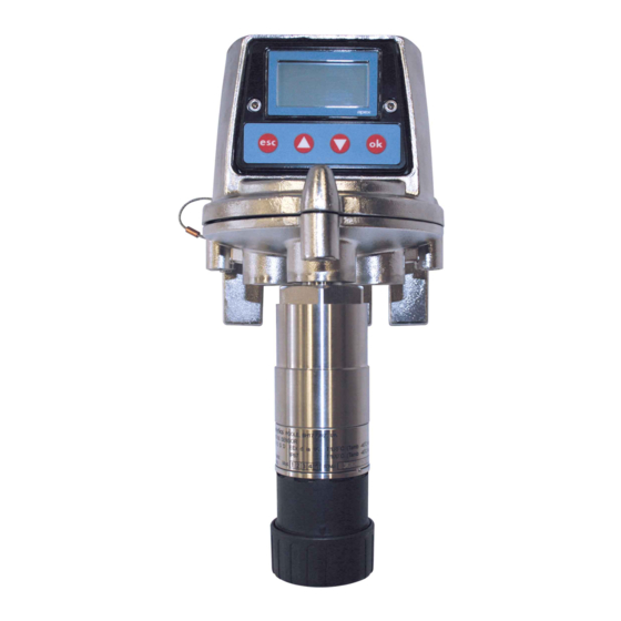
- Page 1 Technical Handbook MAN0604_Issue 09_02-2013 Apex 2110M8030 www.norrscope.com www.norrscope.com Apex...
-
Page 2: Safety
MAN0604_Issue 09_02-2013 Apex 2110M8030 SAFETY Ensure that you read and understand this handbook BEFORE installing/operating the equipment. Pay particular attention to the Safety Warnings. WARningS 1. This gas detection equipment is certified for and intended for use in potentially hazardous areas. Install and use the equipment in accordance with current local and national regulations. - Page 3 Transmitter Unit. 5. Calibration procedures should only be performed by qualified personnel. 6. Ensure that when forcing signals on the Transmitter Unit’s output that the effects on the network and controller are understood. 7. Ensure that the Apex Transmitter Unit or Junction Box flamepath is not damaged during dismantling procedures. The flamepath is formed by the mating surfaces of the unit’s top and base. 8. During installation/maintenance only use the supplied parts. Replacement with alternatives will invalidate certification.
-
Page 4: Table Of Contents
MAN0604_Issue 09_02-2013 Apex 2110M8030 cOnTEnTS SAFETY 1. inTROdUcTiOn 2. OvERviEW Transmitter Unit Certified Sensor Accessories 2.3.1 Certified Junction Box 2.3.2 Collecting Cone 2.3.3 Flow Housing 2.3.4 Weather Housing 2.3.5 Sunshade 2.3.6 Oxygen Transducer Adaptor 2.3.7 Filters 3. inSTAllATiOn General Installation Guidelines Transmitter Unit and Certified Sensor 3.1.1... - Page 5 MAN0604_Issue 09_02-2013 Apex 2110M8030 cOnTEnTS Start-up Passwords 4.3.1 Setting/changing passwords 4.3.2 Password reset Menus 4.4.1 Calibration Menu 4.4.2 Configuration Menu 4.4.3 Display Menu 4.4.4 History Log Menu 4.4.5 Change Passwords Menu 4.4.6 Reset Passwords User Tasks Fault Diagnosis 4.6.1 Displayed Error Messages 4.6.2...
- Page 6 MAN0604_Issue 09_02-2013 Apex 2110M8030 cOnTEnTS A.3 Accessories A.3.1 Certified Junction Box A.3.2 Sunshade A.3.3 Flow Housing A.3.4 Weather Protection A.3.5 Collecting Cone A.3.6 Oxygen Transducer Adaptor A.4 LonWorks Communications Board A.4.1 LonWorks Network Variables A.4.2 Node Object A.4.3 Sensor Object A.4.4 Virtual Function Block A.4.5...
- Page 7 MAN0604_Issue 09_02-2013 Apex 2110M8030...
-
Page 8: Introduction
MAN0604_Issue 09_02-2013 Apex 2110M8030 1. inTROdUcTiOn Apex is a gas detection system that consists of a Transmitter Unit, a certified gas sensor and a set of accessories. The Transmitter Unit, Certified Sensor and Certified Junction Box accessory are all certified for use in potentially hazardous areas and are protected against water and dust ingress to IP67. Typical working environments are oil and gas distribution, petroleum extraction and chemical manufacture. System installation is straightforward. Components should be installed in accordance with the procedures described in this handbook and to local or national installation codes of practice. - Page 9 MAN0604_Issue 09_02-2013 Apex 2110M8030 1. inTROdUcTiOn This handbook consists of the following parts: • Chapter 1 Introduction • Chapter 2 Overview • Chapter 3 Installation • Chapter 4 Operation • Chapter 5 Maintenance • Appendix A Specifications • Appendix B Certification • Appendix C Accessories & Spare Parts •...
-
Page 10: Overview
• Accessories For installation information see Chapter 3. Also see drawing 2110C8049 Outline Dimensions of Certified Transmitter, Sensor & Accessories (available on request from Honeywell Analytics). TRAnSmiTTER UniT The Transmitter Unit provides a mounting point for a Certified Sensor and contains all the electronics associated with the gas detection system. It features an LCD display screen that displays the controlling software menu system, and also a set of buttons that let an operator/user interact with the system by accessing the menus and responding to displayed messages. - Page 11 MAN0604_Issue 09_02-2013 Apex 2110M8030 2. OvERviEW Interconnect PCB Locating pins Captive bolt (3 off) External earth Certified Sensor mounting Cable / conduit entry (2 off) Unit base Cable/conduit entry sealing plug (1 off)
-
Page 12: Certified Sensor
MAN0604_Issue 09_02-2013 Apex 2110M8030 2. OvERviEW 2.2 cERTiFiEd SEnSOR The Certified Sensor consists of the sensor body and one of four types of replaceable gas cartridge and the electronics to output gas sensing data to the Apex Transmitter Unit. The Certified Sensor can be fitted with any one of a number of accessories, the majority of which fit in place of the sensor cap (see 2.3). The four types of cartridge are: • electrochemical cell • catalytic (SG16 type) • oxygen • thick film Caution: Only cartridges with the following part numbers can be fitted to the Certified Sensor: 2110B30x0, 31x0, 32x0, 33x0, 34x0, 35x0 series 2110B3700 - 2110B3999 range Certified Sensor approved to CSA C22.2 No. - Page 13 MAN0604_Issue 09_02-2013 Apex 2110M8030 2. OvERviEW Cap or accessory Seal or optional filter Sensor body Certification label Cartridge Sensor cable All the gas cartridges are the same size except for the Oxygen cartridge, which is larger than the rest. To allow for its extra length an Oxygen Transducer Adaptor, supplied with the cartridge, mounts on the sensor bayonet fixing. The Oxygen cartridge is then inserted and the cap or accessory fitted. 165mm (177mm with...
-
Page 14: Accessories
MAN0604_Issue 09_02-2013 Apex 2110M8030 2. OvERviEW 2.3 AccESSORiES The Apex accessories provide optional equipment that can, for example, protect the Certified Sensor in harsh external environments and assist gas monitoring. All of the sensor accessories are easily fitted. The following accessories are available: • Certified Junction Box (Part Numbers: ATEX Ex d 2110B2100, UL/CSA [Explosion proof] 2110B2103) - two types for remote mounting a Certified Sensor. - Page 15 MAN0604_Issue 09_02-2013 Apex 2110M8030 2. OvERviEW Interconnect External earth Captive bolt (3 off) Unit base Certified Cable / conduit Sensor mounting entry (2 off) 152mm...
-
Page 16: Collecting Cone
MAN0604_Issue 09_02-2013 Apex 2110M8030 2. OvERviEW 2.3.2 Collecting Cone Caution: This accessory should not be used for calibration purposes. Part Number: 2110B2151 160mm The Collecting Cone is only for use when monitoring lighter-than-air gases. Its shape is designed to: • increase the collection area for lighter than air gases • allow the gases to escape so that the time to clear an alarm is not excessively prolonged. -
Page 17: Flow Housing
MAN0604_Issue 09_02-2013 Apex 2110M8030 2. OvERviEW 2.3.3 Flow Housing Part Number: 2110B2140 43mm 53mm The Flow Housing accessory provides a means of applying gas to the sensor for calibration and test (for details see section 4.7). It can also be used in sampling systems where a sample of gas is drawn through a tube to the sensor. -
Page 18: Weather Housing
MAN0604_Issue 09_02-2013 Apex 2110M8030 2. OvERviEW 2.3.4 Weather Housing Caution: This accessory should not be used for calibration purposes. This accessory is not recommended for use in still air conditions. Part Number: 2110B2150 53mm The Weather Housing accessory protects the sensor from hosing down/ cleaning operations and from extreme weather conditions, (e.g. -
Page 19: Sunshade
MAN0604_Issue 09_02-2013 Apex 2110M8030 2. OvERviEW 2.3.5 Sunshade Part Number: 2110B2152 115mm The Sunshade prevents excessive heating of the sensor by direct sunlight. Conforms to cSA c22.2 No. 152 when fitted to the Certified Sensor with specific cartridges installed. See specifications for details. The sunshade is fitted to the sensor body by means of a clamp. 2.3.6 Oxygen Transducer Adaptor 53mm The Oxygen Transducer Adaptor is supplied with the Oxygen cartridge and is necessary because the depth of the Oxygen cartridge is more than that of the other gas cartridges. -
Page 20: Installation
MAN0604_Issue 09_02-2013 Apex 2110M8030 3. inSTAllATiOn The Apex system components can be used together in a variety of ways for different installation requirements in a hazardous environment. For installations of certified components also refer to the Control Drawings in Appendix B. The following types of system installation are typical examples of those that can be made: • Apex Transmitter unit with a Certified Sensor locally mounted at the Transmitter Unit and field wiring from the Transmitter Unit to the system controller. -
Page 21: General Installation Guidelines
• Read all the instructions before starting any of the installation procedures. • Identify a suitable location with a flat surface where the Apex Transmitter Unit/ Certified Junction Box can be mounted. • Identify external cable requirements and the necessary cable/conduit entry ports to be used on the Apex Transmitter Unit/Certified Junction Box. -
Page 22: Transmitter Unit And Certified Sensor
The 24V supply should be free from large transients and fluctuations. The type of cable used for field wiring between the Apex transmitter and control equipment, and between the Apex transmitter and Apex sensor if mounted remotely, should be selected to meet the environmental and hazardous area requirements. The cable internal construction should be a of the screened, multi-core, multi-stranded type. The terminals within the product will accept a maximum conductor size of 2.5mm... -
Page 23: Installing The Transmitter Unit
Isolate all associated power supplies and ensure that they remain OFF during the installation procedure. Ensure a gas free atmosphere. Attach the Apex Transmitter Unit to the supporting structure. Drill two mounting holes (68mm apart) and use the unit’s mounting slots in the base with... - Page 24 MAN0604_Issue 09_02-2013 Apex 2110M8030 3. inSTAllATiOn Cable - using any suitable flameproof cable entry device certified a Equipment to Directive 94/9/EC (ATEX). Note: All unused cable/conduit entries must be sealed with a suitable certified sealing plug (one plug is supplied). Typical wiring arrangements to the Transmitter Unit are (with all cables screened): Single cable/conduit entry Power 4-20mA Digital Comms Relays Cores used 6 10 Twin cable/conduit entries...
-
Page 25: Fitting The Certified Sensor
MAN0604_Issue 09_02-2013 Apex 2110M8030 3. inSTAllATiOn 3.1.2 Fitting the Certified Sensor (1) Fit the Certified Sensor to the Transmitter Unit. Transmitter Unit base Certified Sensor mounting point Certified Sensor Feed the sensor cable through the Certified Sensor mounting point at the front of the Transmitter Unit base. Screw the sensor firmly into the mounting point until it is fully home. Connect the sensor wiring. See the following wiring table and diagram. Terminal Function Colour Recommended Number... - Page 26 Follow the reverse of the removal procedure supporting the top. The top should be positioned using the locating pins on the Apex Transmitter Unit base and then lowered onto the base. Ensure that the lid retaining cable and wiring is not trapped and the O-ring in the top is correctly located.
-
Page 27: Installing The Gas Sensing Cartridge
MAN0604_Issue 09_02-2013 Apex 2110M8030 3. inSTAllATiOn 3.1.3 Installing the Gas Sensing Cartridge (1) Remove the cap from the Certified Sensor body. Rotate the cap or accessory 1/4 turn in an anticlockwise direction to release the bayonet fitting. Fit the gas sensing cartridge into the sensor body. Sensor body... - Page 28 MAN0604_Issue 09_02-2013 Apex 2110M8030 3. inSTAllATiOn Caution: Do not force the cartridge as this may cause damage to the pins of the connecting plugs. Twisting and pushing can bend the pins and make the cartridge inoperative. Plug Socket (2 off)
-
Page 29: Transmitter Unit Configuration
MAN0604_Issue 09_02-2013 Apex 2110M8030 3. inSTAllATiOn 3.1.4 Transmitter Unit Configuration Caution: Do not change either Relay or 4-20mA link setting while unit is powered up. Fault Alarm Alarm J1 J2 J3 The following information specifies the unit configuration options. Relays Links J1, J2 and J3 set the contact operation for the Fault, Alarm 1 and Alarm 2 relays respectively. - Page 30 MAN0604_Issue 09_02-2013 Apex 2110M8030 3. inSTAllATiOn 4-20mA loop The summary table and subsequent diagrams identify the link and terminal settings for 4-20mA loop options. link 4 - 20mA loop topology Terminal Isolated Source Sink 4 - 20mA - 4 - 20mA - not used 4 - 20mA + not used 4 - 20mA + Note: Total 4-20mA loop resistance should be less than 300 ohms. Total power supply loop resistance should be less than 30 ohms (ECC cartridge) or 16 ohms (catalytic cartridge).
- Page 31 MAN0604_Issue 09_02-2013 Apex 2110M8030 3. inSTAllATiOn Current Sink Mode (3-wire) 4 - 20mA + +24V dc Current Source Mode (3-wire) 4 - 20mA - +24V dc...
-
Page 32: Certified Junction Box And Certified Sensor
MAN0604_Issue 09_02-2013 Apex 2110M8030 3. inSTAllATiOn 3.2 CERTIFIED JUNCTION BOX And cERTiFiEd SEnSOR This installation consists of a Certified Junction Box accessory with the Certified Sensor locally mounted at the box together with field wiring. Apex Transmitter Unit with Certified Sensor mounted in Certified Junction Box (North America -style installation) Certified Junction Box Apex Transmitter Unit with Certified Sensor Apex Transmitter Unit... -
Page 33: Installing The Certified Junction Box
MAN0604_Issue 09_02-2013 Apex 2110M8030 3. inSTAllATiOn 3.2.1 Installing the Certified Junction Box Caution: Ensure that the Certified Junction Box flamepath is not damaged during this procedure. The flamepath is formed by the mating surfaces of the Certified Junction Box top and base (see diagrams). Isolate all associated power supplies and ensure that they remain OFF during the installation procedure. Ensure a gas free atmosphere. Certification label Lid retaining... -
Page 34: Fitting The Certified Sensor
MAN0604_Issue 09_02-2013 Apex 2110M8030 3. inSTAllATiOn (4) Fit and connect the field wiring. See the subsequent tables and diagram for wiring details. Use either: Conduit - using one or both of the ¾ NPT conduit entries. Ensure that a conduit sealing fitting is installed within 18" of the enclosure on all conduit runs. Cable - using any suitable flameproof cable entry device certified as Equipment to Directive 94/9/EC (ATEX). - Page 35 MAN0604_Issue 09_02-2013 Apex 2110M8030 3. inSTAllATiOn Terminal/Number Function Colour CAN_L White CAN_H Green or Blue Black Not used Screen * Screen * Earth Green/Yellow * Only connect cable screens to these terminals if they are isolated at the remote end.
-
Page 36: Installing The Gas Sensing Cartridge
MAN0604_Issue 09_02-2013 Apex 2110M8030 3. inSTAllATiOn Set the link on the Interconnect PCB for the required Controller Area network (CAN) setting. See 3.2.4. (4) Refit the top to the Certified Junction Box base. Cautions: Ensure that there is no moisture inside the Certified Junction Box before fitting the lid. Use only the captive bolts supplied, replacement with alternative bolts will invalidate certification. The top should be located using the locating pins on the Certified Junction Box base and then lowered onto the base. Ensure that the lid retaining cable and/or wiring are not trapped and the O-ring in the top is correctly located. - Page 37 MAN0604_Issue 09_02-2013 Apex 2110M8030 3. inSTAllATiOn Caution: Only cartridges with the following part numbers can be fitted to the Certified Sensor: 2110B30x0, 31x0, 32x0, 33x0, 34x0, 35x0 series 2110B3700 - 2110B3999 range Note: For remote CSA Certified Sensor installations combustible cartridges in the range of part numbers 2110B3700 to 2110B3799 MUST NOT BE FITTED. Carefully plug the cartridge into the Certified Sensor body ensuring that the cartridge tab lines up with the recess in the sensor body and push the cartridge, without twisting, until it is fully home.
-
Page 38: Certified Junction Box Configuration
MAN0604_Issue 09_02-2013 Apex 2110M8030 3. inSTAllATiOn Check for correct operation of the system by carrying out the procedures described in Chapter 4. 3.2.4 Certified Junction Box Configuration The following information specifies the Certified Junction Box configuration options. Controller Area Network (CAN )Termination Link - J1 Terminated Unterminated (default) Note: Leave the link in the Unterminated position. -
Page 39: Removing The Transmitter Unit Top
MAN0604_Issue 09_02-2013 Apex 2110M8030 3. inSTAllATiOn Note: The board is supplied with the mounting pillars fitted to it. This procedure describes how to: • remove the Transmitter Unit top • remove the Main PCB assembly from the top • fit the LonWorks Communication Board to the Main PCB • refit the Main PCB assembly into the top •... -
Page 40: Removing The Main Pcb Assembly From The Top
This provides access to the components inside the top. Main PCB Ribbon Potted assembly cable baffle baffle PCB baffle securing screw (2 off) (2) Remove the PCB Baffle from the Transmitter Unit top. Unscrew and remove the two PCB Baffle securing screws. (3) Disconnect the flying lead plug and socket connecting the Main PCB Potted assembly to the top. Slide the Main PCB Potted assembly out of the Apex Transmitter Unit top. -
Page 41: Fitting The Lonworks Communication Board To The Main Pcb
MAN0604_Issue 09_02-2013 Apex 2110M8030 3. inSTAllATiOn 3.3.3 Fitting the LonWorks Communication Board to the Main PCB Main PCB Flying lead Main PCB Potted assembly (1) Place the Main PCB Potted assembly on a flat surface with the flying lead and plug on top. Push the flying lead to one side so that there is clear access to the Main PCB. Remove the LonWorks Communication Board from its antistatic bag. Position the Communication Board over the Main PCB. -
Page 42: Refitting The Main Pcb Assembly Into The Top
Refer to the table and diagram for wiring details. Use either: Conduit - using one or both of the 3/4 NPT conduit entries. Ensure that a conduit sealing fitting is installed within 18" of the enclosure on all conduit runs. Cable - using any suitable flameproof cable entry device certified as Equipment to Directive 94/9/EC (ATEX). Note: All unused cable/conduit entries must be sealed with a suitable certified sealing plug (one plug is supplied with the Apex Transmitter Unit). - Page 43 MAN0604_Issue 09_02-2013 Apex 2110M8030 3. inSTAllATiOn Terminal number Function Min. length of cable from entry point NET1 60mm (Comms NET2 60mm & Power) Ground 60mm Note: Three terminal blocks are provided, any two can be used. 3.3.6 Refitting the Transmitter Unit Top Support the top.
- Page 44 Use only the captive bolts supplied, replacement with alternative bolts will invalidate certification. The top should be located using the locating pins on the Apex base and then lowered onto the base. Ensure no wires are trapped and the O-ring in the top is correctly located.
-
Page 45: Accessories
MAN0604_Issue 09_02-2013 Apex 2110M8030 3. inSTAllATiOn Select (highlight) the Configuration Menu option. Use the up/down keys. Press the ok button. Enter the current Level 2 password. The Configuration Menu is displayed. Configuration Menu Change Cartridge Configure 4-20mA Configure Relays Configure Alarms Configure Digital... - Page 46 MAN0604_Issue 09_02-2013 Apex 2110M8030 3. inSTAllATiOn Sensor body Sensor Rotate the cap in an anticlockwise direction by 1/4 turn to release the bayonet fitting and pull off. (2) Remove the rubber seal or filter from the sensor cap. Lug location Rubber seal Filter The rubber seal or filter is held in place in the cap by its three lugs. Carefully prise the rubber seal or filter free from the lug location points in the cap or accessory. (3) For the Collecting Cone only fit the cone onto the supplied housing. The Collecting Cone is supplied as a kit of two parts that clip together. (4) Fit the rubber seal/filter to the accessory. Ensure that the rubber seal or filter is correctly installed in the accessory the correct way round with the three lugs closest to the front face of the accessory and correctly engaged in the locators.
-
Page 47: Sunshade
MAN0604_Issue 09_02-2013 Apex 2110M8030 3. inSTAllATiOn Certified Sensor Flow Housing 3.4.2 Sunshade The sun shade can be used with other accessories in the range such as the Flow Housing, Weather Protection and Collecting Cone, but should be attached before any other accessories are fitted, or after their removal. To fit the Sunshade accessory carry out the following procedure. (1) Remove the Certified Sensor cap or accessory. Sensor body Sensor The cap or accessory is held by means of a bayonet fitting. Unscrew 1/4 turn anticlockwise... - Page 48 MAN0604_Issue 09_02-2013 Apex 2110M8030 3. inSTAllATiOn Clamp left-hand hole Clamp Self-tapping right-hand screw hole Drive the screw home into the clamp's right-hand hole until the Sunshade's clamp grips the Certified Sensor body tightly. (5) Refit the sensor cap or accessory. Reverse the removal procedure.
-
Page 49: Operation
MAN0604_Issue 09_02-2013 Apex 2110M8030 4. OPERATION The Apex gas measuring system is controlled from the Transmitter Unit via a menu system, displayed on an LCD screen, and a set of control buttons. This chapter provides operational information about the following: • Display and control buttons • Start-up •... -
Page 50: Lcd Screen
MAN0604_Issue 09_02-2013 Apex 2110M8030 4. OPERATION 4.1.1 LCD screen The screen provides a graphical user interface that, during normal operation, displays gas reading information. It also displays information about the system to the user, via a password protected hierarchical system of menus, together with system fault and information messages. -
Page 51: Start-Up
MAN0604_Issue 09_02-2013 Apex 2110M8030 4. OPERATION 4.2 START-UP Switch on the power supply to the Apex Transmitter Unit. With a correctly installed Certified Sensor the following information is shown sequentially on the LCD screen: HONEYWELL ANALYTICS INITIALISING CONNECTING 100 ppm The Transmitter Unit initially waits for the Certified Sensor to stabilise, during which period the 4-20mA output is inhibited (2mA). Wait for 15 minutes to ensure sensor stabilisation has occurred before continuing. If the sensor does not stabilise during the initialisation period (15 minutes), one of the fault (F) or warning (W) alarm messages shown in Section 4.6 is displayed. -
Page 52: Setting/Changing Passwords
MAN0604_Issue 09_02-2013 Apex 2110M8030 4. OPERATION For example the Level 1 Password provides a system operator with access to day-to-day system operations, e.g. resetting alarms, checking the number of hours to the next Certified Sensor calibration, etc. Level 2 Password could be assigned to a technician who needs to carry out more difficult operations such as calibrating the Certified Sensor. Level 3 Password is for the system administrator to initially set and subsequently change passwords. - Page 53 MAN0604_Issue 09_02-2013 Apex 2110M8030 4. OPERATION Navigate to the Change Passwords Menu option. Use the (up/down) keys. Press ok. Enter the current Level 3 password. Use the buttons on the front panel. If setting passwords for the first time after unit delivery or password reset, enter the default password by pressing the (ok, up, down and down) buttons in sequence. Passwords are shown using asterisks (*) on the LCD.
-
Page 54: Password Reset
MAN0604_Issue 09_02-2013 Apex 2110M8030 4. OPERATION Enter the new password . The following screen is displayed: Level 1 Password ReEnter New Password (10) Enter the new password again . The following screen is displayed: Level 1 Password Success! OK:Continue (11) Press ok. The display returns to the Change Passwords Menu. -
Page 55: Menus
MAN0604_Issue 09_02-2013 Apex 2110M8030 4. OPERATION The Main Menu is displayed. Main Menu Calibration Menu Configuration Menu Display Menu History Log Menu Change Passwords Menu Reset Passwords Navigate to the Reset Passwords option. Use the up/down keys. Press ok. At the prompt enter the following sequence of 8 keystrokes: (up, down, ok, esc, esc, ok, down, up) All the passwords are reset to their default value and the display returns to the Main Menu. - Page 56 MAN0604_Issue 09_02-2013 Apex 2110M8030 4. OPERATION Calibration Menu Gas Calibrate Gas Challenge 4-20 mA Set Zero Force 4-20mA Force Relays Force Digital Configuration Menu Change Cartridge Configure 4-20mA Configure Relays Configure Alarms Configure Digital Select Language Main Menu Display Menu...
-
Page 57: Calibration Menu
MAN0604_Issue 09_02-2013 Apex 2110M8030 4. OPERATION 4.4.1 Calibration Menu Caution: The calibration procedure should only be performed by qualified personnel. Caution: "If "Yes" is selected for the "Span Calibrate?" option, the span calibration must be completed successfully. Failure to do so will result in the unit signaling a "Calibration Needed" fault. - Page 58 MAN0604_Issue 09_02-2013 Apex 2110M8030 4. OPERATION Calibration Menu Gas Calibrate This option calibrates the Certified Sensor zero gas point and the span setting point (see 4.7 for details of how to carry out this procedure) Gas Calibrate Span Calibration screen Zero Calibration screen Set Span Use up/ Concentration down (ppm) buttons Zero Gas Apply Gas...
- Page 59 MAN0604_Issue 09_02-2013 Apex 2110M8030 4. OPERATION Gas Challenge Calibration Menu Cautions: Ensure that the area around the sensor is gas free before exiting the Gas Challenge mode. Upon leaving gas challenge mode, all outputs return to their active states (from inhibited).
- Page 60 MAN0604_Issue 09_02-2013 Apex 2110M8030 4. OPERATION 4-20mA Set Zero Calibration Menu This option allows the This option allows 4-20mA Set Zero the zero point within the 4-20mA signal range to be adjusted between 3.5 and 4.5mA. The default setting is 4.0mA. The offset applies to all 4-20mA output states including Inhibit, Warning, Overrange and Alarms. 4-20mA Set Zero screen...
- Page 61 MAN0604_Issue 09_02-2013 Apex 2110M8030 4. OPERATION Force Relays Calibration Menu Caution: Ensure that when forcing a relay response that the effects on the network and controller are understood, e.g. alarm activation, etc. Provides the means to test the operation of the Transmitter Unit's relays by forcing them in turn to be energised/de-energised.
- Page 62 MAN0604_Issue 09_02-2013 Apex 2110M8030 4. OPERATION Calibration Menu Force Digital Caution: Ensure that when forcing a signal on the digital output that the effects on the network and controller are understood, e.g. alarm activation, etc. This option allows the digital output (if a digital communications board is fitted to the Transmitter Unit, e.g. LonWorks) to be forced to output an alarm signal, from Alarm 1 or Alarm 2 or no alarm.
-
Page 63: Configuration Menu
MAN0604_Issue 09_02-2013 Apex 2110M8030 4. OPERATION 4.4.2 Configuration Menu Configuration Menu Change Cartridge Configure 4-20mA Configure Relays Configure Alarms Configure Digital Select Language Configure Backlight Note: The Configure Backlight option is not available on CSA Certified Transmitter Units. The Configuration Menu changes settings for the Transmitter Unit, e.g. alarm operation, and also configures Certified Sensor operations, e.g. when changing the Certified Sensor gas cartridge. This menu is protected by a Level 2 password. - Page 64 MAN0604_Issue 09_02-2013 Apex 2110M8030 4. OPERATION Change Cartridge Change Cartridge screen Follow cartridge change Change instructions cartridge See Section 5 Checking Success? Fault diagnosis Calibration Menu Configure 4-20mA Configuration Menu Provides the means to configure the values for the 4-20mA signal output settings. Three settings are available: Inhibit Value 1mA to 4mA, default is 1mA. Warning Value 1mA to 6mA, default is 3mA.
- Page 65 MAN0604_Issue 09_02-2013 Apex 2110M8030 4. OPERATION Configure 4-20mA Configure 4-20mA screen Use up/down buttons to choose setting from: Select setting Inhibit to change Warning Overrange Use up/down Select value buttons Select another setting? Calibration Menu...
- Page 66 MAN0604_Issue 09_02-2013 Apex 2110M8030 4. OPERATION Configure Relays Configuration Menu This option allows the three Transmitter Unit relays to be configured for the current installation. Latched relays are cleared by the Display Menu => Reset Alarms, Faults option or by switching the power off and on. Configure Relays Configure Relays screen Use up/down buttons to...
- Page 67 MAN0604_Issue 09_02-2013 Apex 2110M8030 4. OPERATION Fault relay configuration example Requirement: Normally De-energised, Non-Latching with the contact Normally Closed. Implementation: Use the Configure Relays menu option to set the Fault relay operation requirement. Place the jumper on the J1 link to set the contact operation as follows:...
- Page 68 MAN0604_Issue 09_02-2013 Apex 2110M8030 4. OPERATION Configure Alarms Configuration Menu Caution: Alarm 2 value can be set below Alarm 1 value. When installed to measure flammable gas it is essential that WARNINGS either the Transmitter unit or control network is configured to Change cartridges using the procedure described below.
- Page 69 MAN0604_Issue 09_02-2013 Apex 2110M8030 4. OPERATION Configure Digital Configuration Menu This menu item displays a screen that reports information about digital communications if a digital communications board is fitted to the Transmitter Unit, e.g. LonWorks. An example of a typical screen is as follows: Configure Digital Network Type: LonWorks Connection Type: FTT-10 Node Id: 00A176094800 Node Address: Baud Rate: 78.0kbit/s...
- Page 70 MAN0604_Issue 09_02-2013 Apex 2110M8030 4. OPERATION Select Language Configuration Menu Provides the means to change the language in which text on the LCD screen is displayed. Select Language Select language screen Choose Use up/down language from buttons list Configuration Menu...
-
Page 71: Display Menu
MAN0604_Issue 09_02-2013 Apex 2110M8030 4. OPERATION 4.4.3 Display Menu Display Menu Reset Alarms, Faults Calibration Info Current Config The Display Menu reports back the current settings for the Transmitter Unit and Certified Sensor, e.g. calibration and configuration setting information. This menu is protected by a Level 1 password. Display Menu Reset Alarms, Faults WARNING Alarms should not be reset until it is confirmed that gas is not present. - Page 72 MAN0604_Issue 09_02-2013 Apex 2110M8030 4. OPERATION Display Menu Calibration Info This option displays a screen that reports information about the calibration of the Transmitter Unit and Certified Sensor. An example of a typical screen is as follows: Calibration Info Last Calib: Next Calib: 4205 Gas: FSD: 1.200 ppm Calib Interval: 4368...
- Page 73 MAN0604_Issue 09_02-2013 Apex 2110M8030 4. OPERATION Second Screen The second screen is displayed after navigating past the last entry on the initial screen by using the down button. A typical example is as follows: Current Config Fault Relay: NE/L Alarm1 Relay: NE/NL Alarm2 Relay: NE/NL Tx Version: 1.02...
-
Page 74: History Log Menu
MAN0604_Issue 09_02-2013 Apex 2110M8030 4. OPERATION History Log Menu View History Log This sub-menu item displays screens that consist of one or more pages of information, each displaying a message, recording the history of the unit since the log was last reset. The most recent event is viewed first. -
Page 75: Change Passwords Menu
MAN0604_Issue 09_02-2013 Apex 2110M8030 4. OPERATION Reset History Log Reset History Log screen Are you sure? Use up/down buttons Messages cleared from log History Log Menu 4.4.5 Change Passwords Menu The Change Passwords Menu allows the system administrator Change Passwords Menu to change the passwords for each of the three levels of access. -
Page 76: Reset Passwords
MAN0604_Issue 09_02-2013 Apex 2110M8030 4. OPERATION Level 1 Password Change Passwords Menu This sub-menu item allows the Level 1 Password to be changed. Level 1 Password Level 1 Password screen Use esc/up/ Enter Old down/ok Password buttons Use esc/up/ down/ok... -
Page 77: User Tasks
MAN0604_Issue 09_02-2013 Apex 2110M8030 4. OPERATION (up, down, ok, esc, esc, ok, down, up) 4.5 USER TASKS The following table provides a quick reference list of typical tasks and how to carry them out via the menu system. Tasks related to:... -
Page 78: Fault Diagnosis
Apex 2110M8030 4. OPERATION 4.6 FAULT DIAGNOSIS Apex system faults can be those displayed on the Transmitter Unit screen or be of a general type. This section describes: • Error messages displayed on the Transmitter Unit LCD screen. These are either fault or warning types. They can normally be corrected at the Transmitter Unit or Certified Sensor. -
Page 79: General Faults
MAN0604_Issue 09_02-2013 Apex 2110M8030 4. OPERATION W: End of Cell Life The cartridge is reaching, or has reached, the end F: End of Cell Life of its useful service life. Warning - replace the cartridge within the next 3 months. -
Page 80: 4-20Ma Output Signal Ranges And Fault Conditions
MAN0604_Issue 09_02-2013 Apex 2110M8030 4. OPERATION 4.6.3 4-20mA output signal ranges and fault conditions Overrange Concentrations Pulsed warnings Warnings Inhibit Fault General Fault Output Signal Level Fault Conditions Type Faults 0 - 0.5mA Sensor Failed (default is 0.5mA) No Cartridge Wrong Cartridge Cartridge Failed... -
Page 81: Clearing Latched Alarms
MAN0604_Issue 09_02-2013 Apex 2110M8030 4. OPERATION 4.6.4 Clearing latched alarms WARNING Alarms should not be reset until it is confirmed that gas is not present. The fault and alarm relays may be set to be latched (see Configuration Menu). So when an alarm message is displayed on the LCD screen it may continue to be displayed even when the fault causing the problem is corrected. -
Page 82: System Calibration
MAN0604_Issue 09_02-2013 Apex 2110M8030 4. OPERATION The menu displays the state of the fault and alarm relays and the overrange. Select Reset Alarms from the list. Press ok. The display returns to the Display Menu. Note: Alarms are not reset until the esc button is pressed to leave the Display Menu and return to the Main Menu. - Page 83 MAN0604_Issue 09_02-2013 Apex 2110M8030 4. OPERATION (1) At the Certified Sensor remove the cap or accessory. Sensor body (3 off) Filter Filter lug location Sensor cap or accessory Rotate the cap/accessory in an anticlockwise direction by 1/4 turn to release the bayonet fitting and pull off. If calibrating a sensor with a non-flammable gas cartridge remove the filter, if fitted, from the sensor cap/accessory and fit it to the Flow Housing.
- Page 84 MAN0604_Issue 09_02-2013 Apex 2110M8030 4. OPERATION Fit the Flow Housing onto the Certified Sensor body. Reverse the cap removal procedure. The following diagram shows the Flow Housing accessory fitted to the Certified Sensor. Certified Sensor Flow Housing Press the esc button at the Transmitter Unit. The Main Menu is displayed. Main Menu Calibration Menu...
- Page 85 MAN0604_Issue 09_02-2013 Apex 2110M8030 4. OPERATION Enter the current Level 2 password. The Calibration Menu is displayed. Calibration Menu Gas Calibrate Gas Challenge 4-20 mA Set Zero Force 4-20mA Force Relays Force Digital Navigate to the Gas Calibrate option. Use the up/down keys.
- Page 86 MAN0604_Issue 09_02-2013 Apex 2110M8030 4. OPERATION (15) Press ok. The LCD screen displays the message: Apply Gas then <OK> (16) Connect the Flow Housing (using either gas pipe) to the regulated cylinder containing a known concentration of the target gas at approximately the sensor alarm point, e.g. 50% LEL Methane in air. It is recommended for most sticky gases the tubing should be PTFE with short pieces of rubber tube to make the final connection due to the inflexibility of PTFE. This minimises...
-
Page 87: Binding Communication Boards To Networks
MAN0604_Issue 09_02-2013 Apex 2110M8030 4. OPERATION 4.8 BINDING COMMUNICATION BOARDS TO NETWORKS This section describes how to carry out the configuration procedure necessary to bind a LonWorks Communications Board to the digital network. As the board forms part of the Transmitter Unit the component becomes a node on the network. The procedure is necessary after fitting a LonWorks Communications Board to an Apex Transmitter Unit and connecting the digital network wiring (also see Chapter 3). - Page 88 MAN0604_Issue 09_02-2013 Apex 2110M8030 4. OPERATION Select the Assert Service PIN option. Use the up/down keys. (10) Press the enter button. This binds the node to the network controller. The display automatically returns to the Configuration Menu. (11) Press the esc button twice...
-
Page 89: Maintenance
The Apex system requires some routine maintenance. This section provides information about the following: • Schedule for routine maintenance • Procedures for routine maintenance/parts replacement 5.1 ROUTINE MAINTENANCE SCHEDULE The following table lists the recommended Apex system maintenance tasks and their frequency. Sensor Type Frequency Maintenance Action Equipment Required All models... -
Page 90: Maintenance Procedures /Parts Replacement
MAN0604_Issue 09_02-2013 Apex 2110M8030 5. MAINTENANCE MAINTENANCE PROCEDURES /PARTS REPLACEMENT The following sections describe how to carry out the tasks listed in the maintenance schedule and how to replace parts suggested by Fault Diagnosis in Chapter 4. It tells how to change the following items: •... -
Page 91: Changing The Certified Sensor Cartridge
MAN0604_Issue 09_02-2013 Apex 2110M8030 5. MAINTENANCE (3) Insert a new filter. Ensure that the filter is correctly placed in the cap the correct way round with the three lugs closest to the front face of the cap or accessory and correctly engaged in the location points. (4) Refit the cap or accessory. Reverse the removal procedure. 5.2.2 Changing the Certified Sensor Cartridge WARNINGS Change cartridges using the procedure described below. - Page 92 MAN0604_Issue 09_02-2013 Apex 2110M8030 5. MAINTENANCE Configuration Menu Change Cartridge Configure 4-20mA Configure Relays Configure Alarms Configure Digital Select Language Configure Backlight Select Change Cartridge from the menu list. Press ok. The Change Cartridge screen is displayed. Change Cartridge Change Cartridge Now...
- Page 93 MAN0604_Issue 09_02-2013 Apex 2110M8030 5. MAINTENANCE Notes: If replacing an Oxygen cartridge with another Oxygen cartridge ensure that the Oxygen Transducer Adaptor is left in place on the Certified Sensor body. If replacing an Oxygen cartridge with a different type of cartridge ensure that the Oxygen Transducer Adaptor is removed from the sensor body.
- Page 94 MAN0604_Issue 09_02-2013 Apex 2110M8030 5. MAINTENANCE Socket (2 off) Plug (2 off) Locating Locating recess Sensor body Cartridge (10) Press ok. The Change Cartridge screen now displays the following message. Change Cartridge Working Please Wait This screen is displayed while the cartridge is checked by the Transmitter Unit.
-
Page 95: Changing The Certified Sensor
MAN0604_Issue 09_02-2013 Apex 2110M8030 5. MAINTENANCE (14) Refit the cap or accessory to the Certified Sensor. Reverse the removal procedure. (15) Check that the system is working correctly. Use the Calibration Menu => Gas Challenge menu option to check correct operation of the unit in the presence of the gas being sensed without triggering alarms, etc. (see Chapter 4). - Page 96 MAN0604_Issue 09_02-2013 Apex 2110M8030 5. MAINTENANCE Caution: For the Transmitter Unit only take care not to damage or strain the ribbon cable connecting the lid and the Interconnect PCB in the base of the unit. For the Transmitter Unit support the top and ensure that it is supported whilst the next two steps are carried out.
- Page 97 MAN0604_Issue 09_02-2013 Apex 2110M8030 5. MAINTENANCE The sensor unscrews in an anticlockwise direction. Feed the connecting cable out through the mounting point. (9) Feed the cable from the replacement Certified Sensor in through the sensor mounting point. (10) Fit the replacement Certified Sensor. Screw the threaded end of the replacement Certified Sensor firmly into the mounting point until it is fully home. (11) Cut the sensor cable to the required length.
-
Page 98: Changing The Transmitter Unit Front Panel Assembly
• All other versions 2110B2820 The assembly is attached to the top of the Transmitter Unit by two screws. Front Panel Apex top Assembly e s c Retaining screws To replace the assembly carry out the following procedure. Isolate all associated power supplies and ensure that they remain OFF during this procedure. -
Page 99: Appendix A - Specifications
MAN0604_Issue 09_02-2013 Apex 2110M8030 APPENDIX A - SPECIFICATIONS This section of the handbook provides specification information about the following components: • Transmitter Unit • Certified Sensor • Cartridges • Accessories • LonWorks Communication Board A.1 TRAnSmiTTER UniT And SEnSOR The Apex Transmitter Unit is designed to operate with the Certified Sensors specified in the tables later in this section. The Certified Sensors are designed so that they all have a common electrical interface to the Transmitters Unit. The cartridge data is digitised and processed into a gas reading by the Certified Sensor. The decision on whether gas alarms are present is also made within the... - Page 100 MAN0604_Issue 09_02-2013 Apex 2110M8030 APPENDIX A - SPECIFICATIONS Default settings Fault Default coil state de-energised de-energised energised Default latch state non-latching non-latching non-latching Default terminal normally open normally open normally open Digital I/O standards: Optional. LonWorks Display: LCD. Information displayed: gas reading, state (OK, fault, inhibit, warning, A1, A2, Overrange), fault/warning codes, Certified Sensor type and diagnostic data.
-
Page 101: Monitoring Functions
Span vs temp ± 1% FSD -25 to 55°C (-13 to 131°F) Speed of response: <0.5s between a step input and a corresponding change in the output. Digital electronics and software meet the requirements of EN50271:2002, Electrical apparatus for the detection and measurement of combustible gases, toxic gases or oxygen – Requirements and tests for apparatus using software and/or digital technologies. Note: For performance specification of complete Apex transmitter + Sensor + Cartridge refer to section A.2 or data sheet for cartridge A.1.5 Environmental Operating temperature: -40 to 65°C (-40 to 149°F) User Interface: -20 to 65°C (-4 to 149°F) -
Page 102: Enclosure
Two threaded holes in the base to accept two certified M25 cable glands (European) or two 3/4” NPT conduit fittings (North American versions). Provision is made to attach a tag carrying an ID number. The enclosure materials for Apex are electro-polished grade 316 stainless steel (to BS3146 ANC 4B FM/BS3146 ANC 4C FM) and Zinc Alloy. Size: 140mm wide x 150mm high x 152mm deep. - Page 103 MAN0604_Issue 09_02-2013 Apex 2110M8030 APPENDIX A - SPECIFICATIONS Certified Sensor: ATEX: II 2 G D Ex d ia IIC Ex tD A21 IP67 Operating temperature codes: T135°C (Tamb -40 to +80°C) T100°C (Tamb -40 to +55°C) Certification Number: Baseefa08ATEX0254X Approvals by UL Class I, Division 1, Groups B, C, D Operating temperature codes: T4 (Tamb -40 to +80°C) T5 (Tamb -40 to +55°C)
-
Page 104: Calibration Intervals
MAN0604_Issue 09_02-2013 Apex 2110M8030 APPENDIX A - SPECIFICATIONS A.1.11 Calibration intervals Cartridge dependent. There is no routine calibration of the Transmitter Unit or Certified Sensor electronics A.2 cARTRidgES The Certified Sensor can be fitted with any one of a number of interchangeable cartridges. Each replaceable cartridge contains a gas sensing transducer and its calibration/manufacturing information. It is possible to replace the cartridge without removing the power from the Certified Sensor, even in hazardous environments. -
Page 105: Cartridge Tables
MAN0604_Issue 09_02-2013 Apex 2110M8030 APPENDIX A - SPECIFICATIONS A.2.1 Cartridge tables This section provides a summary list of the cartridges that can be fitted to the Certified Sensor. Notes: Consult Honeywell Analytics for cartridge availability. For cartridge specifications see the data sheet supplied with each cartridge. Toxic - Electrochemical cell Range Part No: Ammonia 50ppm 2110B3320 Ammonia 100ppm 2110B3330 Ammonia 400ppm 2110B3340 Ammonia 1000ppm 2110B3350 Ammonia 50ppm (-20°C min temp) 2110B3570... - Page 106 2110B3702 Ethylene (see note) 10% LEL 2110B3787 Ethylene 100%LEL 2110B3708 Hydrogen 100%LEL 2110B3707 LPG 100%LEL 2110B3705 Methane 100%LEL 2110B3704 Propane 100%LEL 2110B3701 Propene 100%LEL 2110B3703 Note: Cartridge must be used with Apex revised Certified Sensor Part Nos: ATEX 2110B2070 2110B2073 2110B2074 Flammable - Catalytic SG16 - US/Rest of the world version...
- Page 107 2110B3932 (see note) 100%LEL 2110B3933 100%LEL 2110B3934 100%LEL 2110B3935 100%LEL 2110B3936 100%LEL 2110B3937 Butane 100%LEL 2110B3752 Ethylene 100%LEL 2110B3758 Hydrogen 100%LEL 2110B3757 Methane 100%LEL 2110B3754 Propane 100%LEL 2110B3751 Evaluated to CSA C22.2 No.152. Note: Cartridge must be used with Apex revised Certified Sensor Part Nos: ATEX 2110B2070 2110B2073 2110B2074...
-
Page 108: Accessories
MAN0604_Issue 09_02-2013 Apex 2110M8030 APPENDIX A - SPECIFICATIONS A.2.2 Catalytic SG16 cartridges, Methane and Propane Range: 2110B3701 - Propane, 0 to 100%LEL. 100%LEL eq. 1.7%V/V) 2110B3704 - Methane, 0 to 100%LEL. (100%LEL eq. 4.4%V/V) Operating Temperature Range: -40 to +65°C Temperature Effects: 2110B3704 – Methane, Better than +/-5% LEL 2110B3701 – Propane, +/-6%LEL Operating Humidity Range: 5%rH to 90%rH (99%rH Intermittent – non-condensing.) Humidity Effects: Better than +/-5% LEL. Operating Pressure Range: 80kPa to 110kPa Pressure Effects: Better than +/-5% LEL. Warm-up Time: 30s (typical). 900s (worst case). Response Time: 2110B3701 – Propane, T 8s, T 17s. -
Page 109: Certified Junction Box
MAN0604_Issue 09_02-2013 Apex 2110M8030 APPENDIX A - SPECIFICATIONS Calibration Gas Concentration: 25%LEL to 105%LEL Alarm Threshold Limits: 15%LEL to 100%LEL (Alarm 1 and Alarm 2) Poisoning: The cartridge may become inactive after extensive exposure to silicones, halogenated hydrocarbons, heavy metals or sulfur compounds. Oxygen Deficiency: Deletion of Oxygen as a consequence of displacement by flammable gas can result in the gas reading returning to zero. Storage Conditions: 0 to 25 °C 30% to 70% rH 80kPa to 110kPa This sub-section provides the specifications for each of the accessories available for Apex. A.3.1 Certified Junction Box The Certified Junction Box provides a remote mounting point for the sensor. It is designed to operate... - Page 110 MAN0604_Issue 09_02-2013 Apex 2110M8030 APPENDIX A - SPECIFICATIONS Size: 140mm wide x 95mm high x 152mm deep. Weight: 3000gm. Mountings: Provision for two M10 bolts, centres 68mm apart. Configuration The Certified Junction Box can be configured during installation and operation to accept any of the Certified Sensors it is compatible with (see the gas/cartridge tables in section A.2). Certification and Approvals Hazardous Area Certifications ATEX: Approvals by Baseefa II 2 G D Ex d IIC Ex tD A21 IP67 T100° (Tamb -40 to +55°C) T135° (Tamb -40 to +80°C)
-
Page 111: Sunshade
MAN0604_Issue 09_02-2013 Apex 2110M8030 APPENDIX A - SPECIFICATIONS A.3.2 Sunshade Material: Loaded stainless steel. Size: 145mm high x 115mm wide Weight: 110gm. Conforms to CSA 22.2 No.152 when fitted to the Certified Sensor with specific cartridges installed See specifications for detail. A.3.3 Flow Housing Material: Fortron : PPS (modified Polyphenylene sulphide) ® Size: 43mm high x 53mm diameter. Weight: 26gm. Conforms to CSA 22.2 No. 152 when fitted to the Certified Sensor with specific cartridges installed. See specifications for detail. A.3.4 Weather Protection... - Page 112 MAN0604_Issue 09_02-2013 Apex 2110M8030 APPENDIX A - SPECIFICATIONS A.3.3 Flow Housing Material: Fortron : PPS (modified Polyphenylene sulphide) ® Size: 43mm high x 53mm diameter. Weight: 26gm. Conforms to CSA 22.2 No. 152 when fitted to the Certified Sensor with specific cartridges installed. See specifications for detail. A.3.4 Weather Protection Material: Fortron : PPS (modified Polyphenylene sulphide) ® Size: 75mm high x 53mm diameter. Weight: 60gm. Conforms to CSA 22.2 No. 152 when fitted to the Certified Sensor with specific cartridges installed. See specifications for detail.
-
Page 113: Lonworks Communications Board
The LIFELINE II gas detector has fourteen Network variable outputs, two network variable inputs and four network configuration inputs as shown in the following LonMark Object Diagram. Some or all of these may be bound to a LonWorks network. Descriptions of each variable are given in the subsequent sub-sections. For more information consult Honeywell Analytics. LIFELINE II Gas Detector (SNVT_lev_disc) -
Page 114: Node Object
MAN0604_Issue 09_02-2013 Apex 2110M8030 APPENDIX A - SPECIFICATIONS A.4.2 Node Object The Node object has one network variable input and three network variable outputs. nviRequest input and nvoStatus output The Node object implements SNVTs for object request and status. These complex variables are... -
Page 115: Sensor Object
MAN0604_Issue 09_02-2013 Apex 2110M8030 APPENDIX A - SPECIFICATIONS Calibration Required Transmitter Alarm Setting Failure Sensor Comms Failed 102 Fatal Fault 202 101 Transmitter Failed 204 102 Transmitter Failed Transmitter Failed A.4.3 Sensor Object The sensor object has one network variable input and eleven network variable outputs. -
Page 116: Virtual Function Block
MAN0604_Issue 09_02-2013 Apex 2110M8030 APPENDIX A - SPECIFICATIONS nvoCellLife output This variable reports the total cell life remaining. This is cell type specific, but is typically set for new cartridges at 2 years of service. It is reported in hours of life. NvoNextCal output This variable reports when the next calibration is required. The default is 6 months of service between calibrations. -
Page 117: Implementation Of Nvirequest
MAN0604_Issue 09_02-2013 Apex 2110M8030 APPENDIX A - SPECIFICATIONS nciHighLim1 and nciHighLim2 inputs These network configuration inputs (NCIs) set the alarm thresholds for the sensor. LonMaker automatically loads these from a configuration parameter database when a replace or resynchronise operation is performed. However, updates to these NCIs will have no effect if they contain an illegal value. Additionally, the actual alarm thresholds (which are indicated by nvoAlmThresh1 and nvoAlmThresh2) may differ if changed using the front-panel user interface. -
Page 118: Interpretation Of Nvostatus
The object status contains a great deal of information about the status of a node. Several bits have meaning assigned which is specific to Honeywell Analytics. For example fault_alert (Honeywell nomenclature) has been mapped to mechanical_fault (LonMark nomenclature). The following table lists all of these assignments. Blank entries correspond to unimplemented status bits. -
Page 119: Appendix B - Certification
MAN0604_Issue 09_02-2013 Apex 2110M8030 APPENDIX B - CERTIFICATION This appendix defines the certifications for the Apex gas sensing system components. It includes the CSA and UL Control Drawings, see B.4. B.1 TRAnSmiTTER UniT The Transmitter Unit is designed and approved for use in hazardous areas. There are three certified versions of the Transmitter Unit: • ATEX Part No: 2110B2200 • Part No: 2110B2203 • Part No: 2110B2204 A certification label is located on top of the APEX Transmitter Unit. The label contains all the relevant information regarding the product’s identification and certification state. ATEx Manufacturer’s Trademark & Address... -
Page 120: Certified Sensor
MAN0604_Issue 09_02-2013 Apex 2110M8030 APPENDIX B - CERTIFICATION B.2 cERTiFiEd SEnSOR The Certified Sensor is designed and approved for use in hazardous areas. There are six certified sensor types: Sensor - ECC/Catalytic • ATEX Part No: 2110B2000 or 2110B2070 • Part No: 2110B2003 or 2110B2073 • Part No: 2110B2004 or 2110B2074 Sensor - Thick Film •... - Page 121 MAN0604_Issue 09_02-2013 Apex 2110M8030 APPENDIX B - CERTIFICATION ATEx ATEX Hazardous Manufacturer’s Product Name Area Approval Trademark & Address Certificate No. Test House Explosion Certificate Certified Issue Serial Identification CE Mark - Trademark Protection Code Ambient Status Number/ number of Conforms to all...
-
Page 122: Certified Junction Box
MAN0604_Issue 09_02-2013 Apex 2110M8030 APPENDIX B - CERTIFICATION APEX/MATRIX SENSOR: CLASS I, DIV 1, GROUPS B, C, D OP. TEMP CODE T4 (Tamb. -40 to +75 T5 (Tamb. -40 to +55 Certified Sensor approved to CSA 22.2 No. 152 only when fitted with specific cartridges. See B.5 Control Drawings, CSA (page 126) B.3 CERTIFIED JUNCTION BOX The Certified Junction Box is designed and approved for use in hazardous areas. There are two types of Certified Junction Box: • ATEX Ex d Part No: 2110B2100 •... -
Page 123: Accessories
MAN0604_Issue 09_02-2013 Apex 2110M8030 APPENDIX B - CERTIFICATION ATEx APEX/MATRIX JUNCTION BOX: CLASS I, DIV 1, GROUPS B, C, D OP. TEMP CODE T4 (Tamb. -40 to +80 T5 (Tamb. -40 to +55 CLASS I, DIV 1, GROUPS B, C, D OP. TEMP CODE T4 (Tamb. -40 to +75 T5 (Tamb. -40 to +55 B.4 ACCESSORIES The following accessories conform to CSA C22.2 No. 152 when fitted to the Certified Sensor with cartridge Part No: 2110B3754 installed: •... -
Page 124: Control Drawings
MAN0604_Issue 09_02-2013 Apex 2110M8030 APPENDIX B - CERTIFICATION B.5 CONTROL DRAWINGS... - Page 125 MAN0604_Issue 09_02-2013 Apex 2110M8030 APPENDIX B - CERTIFICATION...
-
Page 126: Appendix C - Accessories & Spare Parts
MAN0604_Issue 09_02-2013 Apex 2110M8030 APPENDIX C - ACCESSORIES & SPARE PARTS This appendix lists the accessories and spare parts available for the Apex system. c.1 AccESSORiES Description Part Number Certified Junction Box for remote Certified Sensor mounting: ATEX Ex d 2110B2100 UL/CSA 2110B2103 Collecting Cone 2110B2151 Flow Housing 2110B2140 Sunshade 2110B2152... -
Page 127: Appendix D - Glossary
MAN0604_Issue 09_02-2013 Apex 2110M8030 APPENDIX D - GLOSSARY Cartridge A replaceable assembly containing a gas transducer and associated calibration information Catalytic Bead Used for the detection of combustible gases. These are made of an electrically heated platinum wire coil, covered first with a ceramic base and then with a final outer coating of catalyst. cE mark Indicates compliance to all relevant European directives. - Page 128 MAN0604_Issue 09_02-2013 Apex 2110M8030 APPENDIX D - GLOSSARY Sensor A gas transducer within a protective enclosure: sensors may be safe or hazardous area mounted, and may also include some driving, interfacing, biasing or signal conditioning circuitry. Transmitter A field device that is locally connected to a gas sensing transducer that translates the raw sensor output into a user useful form, e.g. a display, 4-20mA or digital output. Upper Explosive Limit. Concentration of explosive gas, measured in percentage by volume. %V/V Another way of representing %VOL...