Behringer U-Control UCA202 Operating Manual
Ultra low-latency 2 in/2 out usb/audio interface with digital output
Hide thumbs
Also See for U-Control UCA202:
- User manual (100 pages) ,
- Operating manual (22 pages) ,
- User manual (7 pages)
Table of Contents
Advertisement
Advertisement
Table of Contents

Related Manuals for Behringer U-Control UCA202


Summary of Contents for Behringer U-Control UCA202
- Page 1 Operating Manual Version 1.1 March 2006...
-
Page 2: Important Safety Instructions
U-CONTROL UCA202 IMPORTANT SAFETY INSTRUCTIONS CAUTION: To reduce the risk of electric shock, do not remove the top cover (or the rear section). No user serviceable parts inside; refer servicing to qualified personnel. WARNING: To reduce the risk of fire or... - Page 3 U-CONTROL UCA202 DETAILED SAFETY INSTRUCTIONS: 1) Read these instructions. 2) Keep these instructions. 3) Heed all warnings. 4) Follow all instructions. 5) Do not use this apparatus near water. 6) Clean only with dry cloth. 7) Do not install near any heat sources such as radiators, heat registers, stoves, or other apparatus (including amplifiers) that produce heat.
- Page 4 Additional S/PDIF optical output for direct digital conversion Powered via USB bus–no external power supply needed High-quality components and exceptionally rugged construction ensure long life Conceived and designed by BEHRINGER Germany All Trademarks mentioned belong to their respective owners and are not affiliated with BEHRINGER ®...
- Page 5 U-CONTROL users, and thank you very much for expressing your confidence in us by purchasing the UCA202. It is one of my most pleasant tasks to write this letter to you, because it is the culmination...
- Page 6 U-CONTROL UCA202 I would like to thank all people whose help on U-CONTROL UCA202 has made it all possible. Everybody has made very personal contributions, starting from the designers of the unit via the many staff members in our company to you, the user of BEHRINGER products.
-
Page 7: Table Of Contents
2.1 Hardware connection ... 11 3. OPERATING ELEMENTS AND CONNECTIONS ... 12 3.1 Front panel ... 12 3.2 Rear panel ... 13 4. WORKING WITH THE UCA202 ... 14 4.1 Application example ... 14 5. AUDIO CONNECTIONS ... 16 5.1 Wiring ... 16 5.2 Headphones connection ... -
Page 8: Introduction
Power is supplied to the unit via the USB interface. The LED gives you a quick check that the UCA202 is properly connected to the computer. The UCA202 is the ideal extra for every computer musician. -
Page 9: Before You Started
Please dispose of all packaging materials in an environmentally friendly fashion. Please make sure the unit is provided with sufficient ventilation, and never place the UCA202 on top of an amplifier or in the vicinity of a heater to avoid the risk of overheating. -
Page 10: Online Registration
(alternatively www.behringer.de) and kindly read the terms and conditions of our warranty carefully. Should your BEHRINGER product malfunction, our goal is to have it repaired as quickly as possible. To arrange for warranty service, please contact the retailer from whom the equipment was purchased. -
Page 11: System Requirements
Windows XP, 2000 Use the USB connecting cable supplied with the UCA202 to connect the unit to your computer. The USB connection also supplies the UCA202 with current. You can connect a variety of devices and equipment to the inputs and outputs. -
Page 12: Operating Elements And Connections
UCA202 3. OPERATING ELEMENTS AND CONNECTIONS 3.1 Front panel Fig. 3.1: Front panel UCA202 The LED indicates the status of the USB power supply. DIGITAL OUTPUT: The Toslink jack carries an S/PDIF signal which can be connected via a fiber optic cable, for example, to the digital input of an effects device. -
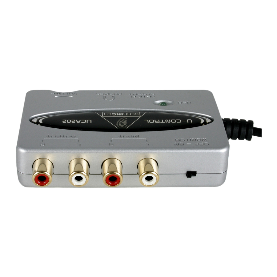
Page 13: Rear Panel
This helps you avoid the damage that is caused by high volume settings. 3.2 Rear panel Fig. 3.2: back of the UCA202 Use the LINE-OUT jacks for audio cables with RCA connectors. Use the LINE-IN jacks for audio cables with RCA connectors. -
Page 14: Working With The Uca202
U-CONTROL UCA202 4. WORKING WITH THE UCA202 4.1 Application example Fig. 4.1: Common version with the UCA202 4. WORKING WITH THE UCA202... - Page 15 (ALT 3-4 and MAIN MIX or ALT 3-4 and TAPE). If you lead the UCA202 back via a channel input (not TAPE INPUT), you can also use the aux path in the channel to set up a monitor mix for live musicians. To do this, use the Aux Send (e.g. Aux 1) in this channel input.
-
Page 16: Audio Connections
Although there are various ways to integrate the UCA202 into your studio or live set-up, the audio connections to be made will basically be the same in all cases: 5.1 Wiring Please use standard RCA cables to connect the UCA202 to other audio equipment. You can also use an adapter cable. Fig. 5.1: RCA cable... -
Page 17: Headphones Connection
U-CONTROL UCA202 Fig. 5.2: Adapter cable with 1/4" jack 5.2 Headphones connection The UCA202 is provided with a headphones jack. Here, you can connect any standard pair of stereo headphones with a 1/8" TRS connector. 5. AUDIO CONNECTIONS... -
Page 18: Specifications
U-CONTROL UCA202 LINE IN Connectors RCA, unbalanced Input impedance approx. 27 kΩ Max. input level 2 dBV LINE OUT Connectors RCA, unbalanced approx. 400 Ω Output impedance Max. output level 2 dBV DIGITAL OUTPUT Socket Toslink, optical cable Output format... - Page 19 Weight approx. 0.12 kg BEHRINGER always takes great care to ensure the highest standard of quality. Any modifications which may be necessary will be made without prior notification. Technical data and appearance of the equipment can therefore differ from the details or illustrations shown.
-
Page 20: Warranty
If the product shows any defects within the specified warranty period that are not excluded from this warranty as described under § 5, BEHRINGER shall, at its discretion, either replace or repair the product using suitable new or reconditioned parts. In the case that other parts are used which constitute an improvement, BEHRINGER may, at its discretion, charge the customer for the additional cost of these parts. - Page 21 5. Any repair or opening of the unit carried out by unauthorized personnel (user included) will void the warranty. 6. If an inspection of the product by BEHRINGER shows that the defect in question is not covered by the warranty, the inspection costs are payable by the customer.
- Page 22 7. Products which do not meet the terms of this warranty will be repaired exclusively at the buyer’s expense. BEHRINGER will inform the buyer of any such circumstance. If the buyer fails to submit a written repair order within 6 weeks after notification, BEHRINGER will return the unit C.O.D. with a separate invoice for freight and packing. Such costs will also be invoiced separately when the buyer has sent in a written repair order.