
Related Manuals for Dräger Cato


Summary of Contents for Dräger Cato
- Page 1 ® Cato edition Anaesthetic Workstation Instructions for Use Software versions: Ventilator: ...... 7.n Monitor: ......2.n...
- Page 2 Working with these Instructions for Use Working with these Instructions for Use In the header line... Operation Manual / Spontaneous the subject of the main section Select Manual / Spontaneous mode Spontaneous breathing The sub-section title is given underneath the main title to help you find your way rapidly through the manual.
-
Page 3: Table Of Contents
Contents Contents For your safety and that of your patients Intended use Quick start in an emergency Operating concept Preparing for use Operation Monitor functions Troubleshooting (messages - cause - remedy) Care Check operational readiness What's what Technical data Descriptions Index... -
Page 4: For Your Safety And That Of Your Patients
For Your Safety and that of Your Patients For Your Safety and that of Your Patients Strictly follow the Instructions for Use Any use of the apparatus requires full understanding and strict observation of these instructions. The apparatus is only to be used for purposes specified here. Maintenance The apparatus must be inspected and serviced regularly by trained service personnel at six monthly intervals... -
Page 5: Intended Use
Expiratory flow curve. Inspiratory and expiratory O concentration. ® Do not use Cato for nuclear spin tomography. Inspiratory and expiratory concentration of N O and The functioning of the apparatus may be impaired. anaesthetic halothane, enflurane, isoflurane, sevoflu- rane and desflurane. - Page 6 Intended use ® Anaesthetic Workstation Cato Accessories The following parameters are monitored: Airway pressure. Expiratory minute volume. Inspiratory O concentration. Inspiratory and expiratory CO concentration. Inspiratory anaesthetic concentration. Optional: Functional O saturation and pulse. Inspiratory breathing gas temperature with invariable upper alarm limit.
-
Page 7: Quick Start In An Emergency
Quick start in an emergency Quick start in an emergency Plug the gas connectors into the gas supply wall sockets. Cato edition 1 The O , AIR and N O pressure gauges must be in the green range. Plug the power plug into the mains. - Page 8 Gas failure If AIR (medical compressed air) fails – Cato automatically switches over to O If O fails – Cato automatically switches over to AIR. An audible warning is emitted (O shortage warning). N delivery is blocked: If O and air fail:...
-
Page 9: Operating Concept
Operating concept Contents Operating concept Contents Page Operating concept, general ..............10 Master switch for electricity supply ............10 Operating concept of the ventilator ............11 Keys with dedicated function ..............11 Display window without dialogue function ..........12 Display window with dialogue function ............ 12 Operating concept of the monitor ............ -
Page 10: Operating Concept, General
Operating concept Operating concept, general Master switch for electricity supply Operating concept, general Master switch for electricity supply Master switch 1 Press to switch on Dialogue: Monitor and ventilator feature a dialogue with the user mediated by: keys, rotary controls, displays and beeps. -
Page 11: Operating Concept Of The Ventilator
Operating concept Operating concept of the ventilator Keys with dedicated function Operating concept of the ventilator Keys with dedicated function – for setting the operating modes Left-hand side: Key for manual ventilation or spontaneous breathing. Key for IPPV mode. Right-hand side: Key for leakage test and compliance measurement. -
Page 12: Display Window Without Dialogue Function
Operating concept Operating concept of the ventilator Display window without and with dialogue function Display window without dialogue function Top left: Continuous indication of the relative piston movement (in % referred to the set stroke volume V The set operating parameters correspond with the keys below: –... -
Page 13: Operating Concept Of The Monitor
Operating concept Operating concept of the monitor Keys with dedicated function, Displays Measured values with grey numerals Operating concept of the monitor Keys with dedicated function (Hardkeys) The right-hand side is reserved for operating elements, the left-hand side for displays. This key switches the monitor from standby to measuring mode and vice versa. -
Page 14: Screen Structure
Operating concept Operating concept of the monitor Screen structure, Screen saver Rotary control Screen structure Status field Alarm field Status field top: contains information on the current alarm mode of the monitor. Measured Alarm field top: Graphic field value field indicates any alarms and their priority. - Page 15 Operating concept Operating concept of the monitor Rotary control Press rotary control = confirm selection. Standby / Configuration Alarms inactive! defaults anaesth. gas warning calibrating The selection is confirmed and appears in dark type on a light background. pulse tone 0 1 2 3 4 6 7 8 9 alarm tone...
-
Page 16: The Various Screen Displays
Operating concept Operating concept of the monitor The various screen displays The various screen displays 1 The three different screen displays are invoked by pressing 2 Press to return to the standard screen from any screen display. The standard screen IPPV alarm limits with the CO curve and another selectable curve. -
Page 17: Preparing For Use
Preparing for use Contents Preparing for use Contents Page Connecting the equipment ..............18 Electricity and gas supply ................ 18 Auxiliary electrical equipment ..............18 Anaesthetic gas scavenging system (AGS) ..........19 Anaesthetic agent vaporiser ..............19 Uninterruptible power supply ..............20 External equipment .................. -
Page 18: Connecting The Equipment
6 Sub-D socket for connecting the uninterruptible power supply (UPS), see page 20. On connection to the Sub-D socket, the UPS can be switched off using the main switch. The auxiliary power sockets and UPS are not installed in the Cato ceiling version. -
Page 19: Anaesthetic Gas Scavenging System (Ags)
Preparing for use Connecting the equipment Anaesthetic gas scavenging system (AGS) Anaesthetic agent vaporiser Anaesthetic gas scavenging system (AGS) Connect the transfer hose to the scavenging adapter – first time only, it then remains in place. 1 Insert the scavenging adapter in the breathing system from below until it engages. -
Page 20: Uninterruptible Power Supply
Cato will be de-energised. However, auxiliary equipment powered by the refrigerator connector on the side of the Cato will still be powered. 1 Plug the power plug of the Cato into the socket of the UPS. USV - Ein / On... -
Page 21: Checking Readiness For Operation With Checklist
Preparing for use Checking readiness for operation with checklist Checking readiness for operation with checklist It is assumed that the following conditions have been met: The equipment and its accessory parts have been cleaned and disinfected – refer to page.......... 83 onwards The unit is fully equipped for the application in question –... -
Page 22: Vapor
Preparing for use Checking readiness for operation with checklist Vapor Anaesthetic gas scavenging Vapor The illustration shows a Vapor 2000 1 The control dial is engaged at »0«. 2 Filling level OK – check filling level in viewglass. – Last inspection less than six months ago. Safety fill: 3 The sealing plug is inserted and secured with the lever. -
Page 23: Breathing System
– Soda lime container is securely tightened – up to the end stop (clockwise). Emergency ventilation bag (not shown) – Bag is complete with mask and hung from the side of the Cato. – Bag functions correctly. Check and tick off. -
Page 24: Water Traps
Preparing for use Checking readiness for operation with checklist Water traps, Reserve gas cylinders Pipelinie gas supply, Gas delivery Water traps 1 Water traps are recommended in both the inspiratory and the expiratory lines during prolonged anaesthesia, low-flow anaesthesia and when using humidified breathing gas. -
Page 25: Oxygen Ratio Control (Orc)
Preparing for use Checking readiness for operation with checklist Oxygen Ratio Control (ORC) Flush, Secretion aspirator Oxygen Ratio Control (ORC) 1 Slowly close O delivery valve – – check: the N O flow decreases to less than 0.8 L/min proportionally with the O flow for ORC low-flow, the N O flow decreases to »O«... -
Page 26: Power Supply
– Two alarm tones sound. – The internal program memories are tested. – The self-test is completed after approx. 1 minute. The following display appears on the monitor: Technology for life Cato SW-Version 2.05 02-05-00 self-test »Self-test« is displayed on the ventilator. -
Page 27: Fresh Gas - External Outlet (Optional)
Preparing for use Checking readiness for operation with checklist Self-test Fresh gas - External outlet If the self-test reveals a fault impairing the equipment's safety, the following message appears on the monitor: »Not ready«. The machine cannot switch to Standby and cannot be switched to measuring mode. -
Page 28: Selecting Anaesthetic Agent
Preparing for use Checking readiness for operation with checklist Selecting anaesthetic agent Selecting anaesthetic agent The machine automatically identifies the newer Vapor models with code for halothane, enflurane and isoflurane, sevoflurane and desflurane. Sevoflurane and desflurane are only identified by equipment built after July 1994 or which has been upgraded. -
Page 29: Automatic Calibration Of O 2 /Flow Sensors
Preparing for use Checking readiness for operation with checklist Automatic calibration of the O /flow sensors Manual calibration of the O sensor The following symbols are used: ? = Enquires whether an action has been performed or a setting made. = Waiting period. -
Page 30: Manual Calibration Of The Flow Sensor
Preparing for use Checking readiness for operation with checklist Manual calibration of the flow sensor Manual calibration of the flow sensor – The flow sensor can be calibrated by hand while O calibration is still in progress, either in the machine or after being removed from the machine. -
Page 31: Ventilator Start-Up Test
Preparing for use Checking readiness for operation with checklist Ventilator start-up test Ventilator start-up test The ventilator must not be connected to the patient during this test! Quantitative test to establish the integrity of the anaesthetic system. The test cannot be performed until O and flow calibration is complete and the relevant sensors have been installed in the anaesthetic system. - Page 32 Preparing for use Checking readiness for operation with checklist Ventilator start-up test The dialogue continues on the ventilator: 1 Test block No. 3 and display: Fresh gas occl? 3 Close all three delivery valves! Confirm: 2 Press rotary control on ventilator! 1 Display: APL = 30 mbar? 4 Set pressure limiting valve to »MAN«...
- Page 33 Preparing for use Checking readiness for operation with checklist Ventilator start-up test 1 Display: Leak IPPV = xxx mL If greater than 175 mL/min: Repair leak, particularly for low-flow, or continue if not problematical – Confirm: 2 Press rotary control on ventilator! 1 Display with test block No.
- Page 34 Checking readiness for operation with checklist Ventilator start-up test 1 Press rotary control on monitor – The machine changes to »standby« mode and the following display appears (example): Standby Cato SW-Version 2.05 02-05-00 erase trend config. Select ventilation mode at the ventilator...
-
Page 35: Operation
Operation Contents Operation Contents Page Manual / Spontaneous ................36 Select Manual / Spontaneous mode ............36 Spontaneous breathing ................36 Manual ventilation ..................37 Manual ventilation following a power failure ..........37 Emergency ventilation following a gas failure ........... 37 Fresh gas - External outlet (optional) ............ -
Page 36: Manual / Spontaneous
Operation Manual / Spontaneous Select Manual / Spontaneous mode Spontaneous breathing Manual / Spontaneous Before connecting a patient Check workstation with checklist (see page 21 onwards). – Check that breathing system is complete (see page 23) and – perform leakage test (see page 31 onwards). Select Manual / Spontaneous mode 1 Press »MAN SPONT«... -
Page 37: Manual Ventilation
Operation Manual / Spontaneous Manual ventilation Manual ventilation following a power failure Emergency ventilation following a gas failure Manual ventilation with breathing bag »PEEP« and pressure limitation »P « are inactive. The airway pressure is limited via the pressure limiting valve APL. -
Page 38: Fresh Gas - External Outlet (Optional)
Intake measurement is performed without connection to the breathing phase. There is no pressure monitoring. When switching on and in the event of a power failure lasting longer than 2 minutes, Cato switches automatically to the internal fresh gas outlet. -
Page 39: Ippv
Operation IPPV Selecting IPPV mode IPPV Selecting IPPV mode Secretion aspirator may only be used in »MAN/SPONT« mode or with disconnected Y-piece. After switching on, the ventilation parameters set prior to delivery or subsequently programmed by DrägerService are active in IPPV mode. 1 Set the values required for the patient. -
Page 40: Automatic Compliance Correction
Operation IPPV Automatic compliance correction Only set the effective tidal volume! The compliance of the breathing system and of the hoses used is established by the equipment during the self-test or if a leakage test is started manually. The reduction in tidal volume due to system compliance is then corrected automatically during ventilation so that the patient actually receives the set tidal volume. -
Page 41: Simv
Operation SIMV Selecting SIMV mode SIMV Selecting SIMV mode Secretion aspirator may only be used in »MAN/SPONT« mode or with disconnected Y-piece. In order to prevent the mechanical mandatory ventilation stroke from being applied during the expiratory sponta- neous breathing phase, a special trigger ensures that the mandatory ventilation stroke is controlled by the patient and consequently synchronized with spontaneous breathing (this is described in detail on page 133). -
Page 42: Paediatric Use
Operation Paediatric use Paediatric use Infant hose set Infant hoses must be used for ventilation volumes of less than 200 mL. If a breathing gas humidifier is used, water traps must be installed at the lowest points of the breathing hoses on both the inspiratory and the expiratory side. -
Page 43: Anaesthesia Ventilation With The Kuhn System
Operation Paediatric use Anaesthesia ventilation with the Kuhn system Then switch to »standby« (see page 48) and call up the leakage test so that the new compliance can be calculated. Invoking the leakage test 1 Press »TEST« on the ventilator for at least three seconds. -
Page 44: Monitoring With Reduced Alarm Limits
Operation Monitoring with reduced alarm limits Checking water traps Monitoring with reduced alarm limits The »IPPV alarm limits« are automatically activated on the monitor when a ventilation frequency equal to or greater than 6 breaths per minute is set in »IPPV« and »SIMV«... -
Page 45: Checking The Soda Lime
Operation Replace water separator Checking the soda lime in the breathing hoses – Water traps must be fitted at the lowest point in the hose and hang downwards. – They must be checked regularly and drained if necessary. Note hygiene regulations – risk of infection! The hose system remains sealed. -
Page 46: Secretion Aspirator (Optional)
Operation Anaesthetic vaporiser Secretion aspirator (optional) Anaesthetic vaporiser The illustration shows a Vapor 2000. – Control dial with scale in % anaesthetic agent by volume. – »0« button – engages in zero position »0«. – Locking lever – Vapor is locked onto the plug adapter. Metering anaesthetic agent: 1 Press »0«... - Page 47 Operation Changing patients Changing patients Changing parts Refer to page 83 onwards for a schematic overview and description of methods for cleaning and disinfection. Maintenance intervals: page 106. Machine in »standby« mode – Vapor: control dial set to »0« = Off. The T-piece and filter are not required when using a Y-piece with Luer lock.
-
Page 48: Set Machine To »Standby
On Vapor: set control dial to »0«. After use If operation is interrupted for several hours, we recommend that you do not leave the Cato in »Standby« mode but switch it off completely. Turn the master switch to »O« = Off –... -
Page 49: Monitor Functions
Monitor functions Contents Monitor functions Contents Page Screen saver ................... 50 Standby screen ..................50 Configuring monitor functions in »standby« .......... 51 Invoking the configuration menu .............. 51 Changing default values ................51 Pulse tone, alarm tone, mode ..............52 Parameters, record, interfaces .............. -
Page 50: Screen Saver
Screen saver Standby screen Screen saver If none of the operating elements on the Cato is operated in »standby« for approx. 2 minutes, the screen switches off and becomes dark. The yellow LED in the standby key and the word »Standby« on the ventilator light up. The monitor display is immediately restored as soon as any key is pressed. -
Page 51: Configuring Monitor Functions In »Standby
Configuring monitor functions in »standby« Invoking the configuration menu Standby The configuration menu is called up by pressing the softkey »config«. Cato Configurations which are set under »defaults« in SW-Version 2.05 »standby« mode remain active whenever the machine 02-05-00 is switched on again. -
Page 52: Pulse Tone, Alarm Tone, Mode
Monitor functions Configuring monitor functions in »standby« Changing default values Pulse tone, Alarm tone, Mode The vertical selection area is displayed. Standby / Configuration Alarms inactive! defaults anaesth. gas warning calibrating The menu for configuring the defaults appears with Halothane settings: default -sensor... -
Page 53: Parameters, Record, Interfaces
Monitor functions Configuring monitor functions in »standby« Parameters, Record, Interfaces Parameters The settings for the following parameters are defined via Standby / Configuration Alarms inactive! this menu: defaults anaesth. gas warning calibrating – SpO -measurement on • off – sidestream - measure. -
Page 54: Alarm Limits, Curves, Basic Configuration
Standby / Configuration Alarms inactive! These alarm limits are automatically active after anaesth. gas defaults warning calibrating – switching on the Cato, pulse tone 0 1 2 3 4 6 7 8 9 – selecting »default«. alarm tone 1 2 3... -
Page 55: Calibration
Monitor functions Configuring monitor functions in »standby« Calibration Calibration This menu is used for the following tests and calibrations: Standby / Configuration Alarms inactive! – Calibrate O -sensor with 21 Vol.% O calibrating Calibrate O sensor after – Calibrate flow sensor replacing sensor and after 24 hrs. -
Page 56: Alarms, Anaesthetic Agent
Anaesthetic agent The anaesthetic vaporizer is automatically recognized by Standby / Configuration Alarms inactive! the Cato on account of an optical code. However, sevo- anaesth. gas warning calibrating defaults flurane and desflurane vaporizers are only recognized... -
Page 57: Monitor Functions During Operation
Monitor functions Monitor functions during operation Changing to measuring mode from »standby« Select standard screen, Select data screen Monitor functions during operation Changing to measuring mode from »standby« The monitor automatically changes to measuring mode when »standby« mode is deactivated on the ventilator or a ventilation pattern is set (»IPPV«, »SIMV«) or »MAN/SPONT«. -
Page 58: Select Trend Screen With Zoom Function
Monitor functions Monitor functions during operation Select trend screen with zoom function Select trend screen with zoom function This screen presents the development of measured values over time since measurement commenced. Values can be saved for a maximum of eight hours. The following combinations can be displayed: –... -
Page 59: Other Trend Combinations
The trend memory and list are erased together! This is Standby only possible in »standby« mode! Press on the monitor in order to switch to »standby«. This is only possible if the ventilator is Cato already on »standby«! SW-Version 2.05 02-05-00 erase Press the softkey »erase trend«. -
Page 60: Softkeys
The set limit values only apply temporarily! They are overwritten by the standard alarm limits when – the Cato is switched off; – the setting »default« is selected and confirmed under »warning«. To change alarm limits:... -
Page 61: Activate And Deactivate Co 2 Alarms
Monitor functions Softkeys Activate and deactivate CO alarms Auto set/Ventilation alarm Activate and deactivate CO alarms In »MAN/SPONT« monitoring mode, the alarm limits for Man./spont. alarm limits inspiratory and expiratory CO are deactivated; only the -apnoea alarm is active. This alarm can also be alarm limits deactivated by pressing the »CO... -
Page 62: Alarm Information
Monitor functions Softkeys Alarm information Select list display Alarm information The measured value field is erased and all active IPPV alarm limits % HAL HIGH !!! alarms listed when this softkey is pressed. ET CO2 LOW !! alarm The display can only be viewed as long as the key is limits pressed. -
Page 63: Select Curves
Monitor functions Softkeys Curve selection Curve selection Only possible in the standard screen! IPPV alarm limits A second curve for the bottom half of the screen can be selected from the menu presented here to complement alarm limits the CO concentration curve (CO ) which is always auto set... -
Page 64: Configuration During Operation
Monitor functions Softkeys Configuration during operation Configuration during operation The menu displayed during operation shows the functions required for measuring mode. The functions are selected as described for other menus. The settings made here only apply for the present operation. Press the softkey »config.«... -
Page 65: Alarm Concept
Monitor functions Alarm concept Alarm priority Alarm concept Alarm priority The monitor alarms are combined with those of the ventilator, arranged in order of priority and assigned to certain tones or tone sequences. This information is presented in keeping with the situation, in separate fields for: Warning marked »... -
Page 66: Displaying All Alarms
Monitor functions Alarm concept Alarm priority alarm on/off Displaying all alarms IPPV alarm limits % HAL HIGH !!! Press the softkey »alarm info« and keep pressed. ET CO2 LOW !! alarm The alarm texts of all warning, caution and advisory limits messages are displayed in order of priority. -
Page 67: Adjusting To The Ventilation Mode
Monitor functions Alarm concept Adjusting to the ventilation mode Adjusting to the ventilation mode For »IPPV", »MAN/SPONT« and »SIMV« ventilation modes The alarm limits are switched over automatically with the change of ventilation mode. In »IPPV« and »SIMV« modes, the »IPPV alarm limits« alarm mode is automatically activated on the monitor if the ventilation rate is equal to or greater than 6 breaths per minute. -
Page 68: Heart/Lung Mode (Hlm)
Monitor functions Alarm concept Heart/lung mode (HLM) Heart/lung mode (HLM) A special alarm mode can be activated during operation Man./spont. alarm limits for the function »warning« in the »Configuration« menu for operation with a heart/lung machine (»HLM« mode). alarm limits All apnoea alarms are deactivated in this mode and the etCO gas values are displayed continuously without connection... -
Page 71: Troubleshooting (Messages - Cause - Remedy)
Messages, cause and remedy Inhalt Messages, cause and remedy Contents Page Where messages occur ................72 Location of valves and subsystems ............73 Messages on the monitor ................ 74 Messages on the ventilator ..............78... -
Page 72: Where Messages Occur
Messages, cause and remedy Where messages occur Where messages occur Warning, caution and advisory messages These are the three types of message output by the Alarm field system and displayed in the alarm field. They are classified in order of priority and listed alpha- betically in the following tables. -
Page 73: Location Of Valves And Subsystems
Messages, cause and remedy Location of valves and subsystems Location of the subsystems: Location of valves in the breathing system: Subsystem 3 Vapor Pneumatic interface Inspiration POP-OFF Exspiration Pressure limitation The valves are numbered as shown in the following schematic – V1, V2, ... Subsystem 1 Subsystem 2 Piston pumpe... -
Page 74: Messages On The Monitor
Messages, cause and remedy Messages on the monitor Messages on the monitor Alarm messages are assigned to three priority classes Alarm field (alarm priority) on the monitor of the Cato: ! ! ! – Warning – Caution – Advisory The patient's condition must be checked first,... - Page 75 Messages, cause and remedy Messages on the monitor Messages on the monitor Messages Cause Remedy APNOEA PRES Ventilation at a standstill. Patient must immediately be ventilated by hand! No change of pressure detected for 15 seconds; 30 seconds in the case of SIMV alarm limits. Check fresh gas setting on anaesthetic unit.
- Page 76 Messages, cause and remedy Messages on the monitor Messages on the monitor Messages Cause Remedy ET CO2 LOW End-expiratory CO concentration below lower Check ventilation. alarm limit for at least two breaths. EXP-VALVE ? Fault in expiration valve. Measured value for minute Check expiration valve.
- Page 77 Messages, cause and remedy Messages on the monitor Messages on the monitor Messages Cause Remedy PRESSURE LTD !!, (!) Ventilator operating with pressure limitation. Check tube/filter. Change in lung compliance? Tube kinked? Increase Pmax or decrease V Microbial filter in inspiratory line soiled? necessary.
-
Page 78: Messages On The Ventilator
Messages, cause and remedy Messages on the ventilator Messages on the ventilator Messages Cause Remedy ???? Internal electronic fault. Call DrägerService. compliance test The hose compliance is being tested during the leakage test in »standby« mode. Equipment fault Attempt to cancel self-test when Acknowledge to cancel alarm –... -
Page 79: Care
Care Contents Care Contents Page Stripping down machine ............... 80 Dismantling parts .................. 81 Disinfection – cleaning – sterilization ............ 83 Care methods ..................84 Care schematic ..................84 Care intervals ..................84 Disposing of consumable articles ............85 Wipe cleaning ..................85 Disinfectant cleaning in machines ............ -
Page 80: Stripping Down Machine
Care Stripping down machine Remove anaesthetic gas scavenging system Stripping down machine Swing up table top to remove piston pump: (only possible in »standby«) 1 Swing lever as far as possible to unlock. 2 Hold breathing system by handle and lift out. Do not damage flat seals –... -
Page 81: Dismantling Parts
Care Dismantling parts T-piece of measured gas hose Inspiratory O sensor Temperature sensor, Flow sensor Dismantling parts T-piece of measured gas hose (if used) 1 Remove filter. Inspiratory O sensor (if used) Must not be disinfected in liquid or autoclaved! Wipe any dirt off housing or lead with damp disposable cloth. - Page 82 Care Dismantling parts Breathing system Piston pump Breathing system Remove flow sensor. Unscrew pressure limitation valve APL. Dismantle breathing valves – valve discs must be handled with care. Replace measured gas return hose if contamination is possible. 1 Release the five quick-release screws by turning through a quarter-turn with a 6 mm hexagon key.
-
Page 83: Disinfection - Cleaning - Sterilization
Care Disinfection – cleaning – sterilization Agents and methods for disinfection, cleaning and sterilization Disinfection – cleaning – sterilization Agents and methods for disinfection, cleaning and sterilization Only products from the list of surface disinfectants may be used for disinfection. Products based on –... -
Page 84: Care Methods
Care Care methods Care schematic Care methods Care schematic Strip down machine Machine without parts in contact Dismantle parts in contact with patient gas with patient gas Manual preliminary In automatic disinfection cleaning unit ANDA / Purfactor In automatic dis- infection unit Aseptor Manual, scrubbing, wipe and instrument disinfection... -
Page 85: Disposing Of Consumable Articles
Alkaline or chlorinated cleaning and disinfectant agents must not be added due to the risk of corrosion! Disinfection with formaldehyde vapour Cato parts which can be treated in this way are listed in the table on page 87. Parts in contact with breathing gas (breathing hoses,... -
Page 86: Sterilization With Ethylene Oxide
This impairs the service life of the cell! Steam sterilization at 121 or 134 °C Cato parts which can be sterilized in this way are listed in the table on page 87. Steam sterilization must be preceded by sterilization with moist heat and/or wipe cleaning. -
Page 87: Tabular Summary
Care Care methods Tabular summary Tabular summary Method Disinfection by Cleaning with Formaldehyde Steam sterilization at 121 °C at 134 °C Machine components wiping or immersion automatic cleaners vapour Stripped down basic machine Wipe Parameter box (optional) Wipe Rubber parts: Tube / mask Y-piece Breathing hoses... -
Page 88: Disposal Of Used Batteries And O 2 Sensors
Dispose of used batteries in accordance with local waste disposal regulations. Used O sensors can be returned to Dräger. Disposal of apparatus – at the end of its useful life. Cato can be returned to Dräger for disposal in accordance with environmental regulations. -
Page 89: Reassembling System
Care Reassembling system Assemble piston pump and breathing system Reassembling system Reassemble cleaned, disinfected and sterilized parts Assemble the piston pump Check individual parts: Gaskets: pressure marks? cracks? Diaphragm: cracks? holes? deformation? Defective parts must be replaced! 1 Fit roller diaphragm – production mark visible at the outside (arrow). - Page 90 Care Reassembling system Fit piston pump and breathing system Replace O sensor for gas sampling system Fit valves Assemble and fit the inspiratory O sensor Fit the piston pump Swing up table top 1 Handle in starting position. Do not damage gaskets when fitting pump! Hold piston pump by its handle and insert in machine –...
- Page 91 Care Reassembling system Connect fresh gas hose Connect pressure measuring line with filter Fill soda lime container Connect fresh gas hose 1 to breathing system from below with plug connector. Connect pressure measuring line with filter 2 Plug pressure measuring line into coupling – until it engages.
- Page 92 Care Reassembling system Connecting anaesthetic gas scavenging system (AGS) Connect sample line Connecting anaesthetic gas scavenging system (AGS) 1 Insert the transfer hose, complete with scavenging adapter, into the breathing system from underneath until it engages, or connect the hose to the scavenging adapter of the semi open system.
- Page 93 5 Install hose between negative pressure outlet and secretion collecting vessels. 6 Connect the gas outlet on the Cato to the ejector. 7 Plug the aspiration hose with handpiece onto the inlet. Secure the aspiration hose in the clamp.
- Page 94 Care Reassembling system Connecting external equipment Connecting equipotential bonding Connecting to electricity supply Connecting external equipment Configuration of the interfaces is described on page 53. Connection via the protocol interface 1 with data cable for printers with serial interface, e.g. Desk-Jet (Hewlett-Packard) for e.g.
-
Page 95: Spo 2 Measurement (Optional)
Care Reassembling system measurement Safety and precautions Choice of sensor measurement (optional) Safety and precautions – The sensor must not be applied to limbs together with an arterial catheter, infusion or sphygmomanometer cuff. – Blood circulation must not be impeded during application of the sensor. -
Page 96: C-Lock-Ecg Synchronization (Optional)
Care Reassembling system measurement Choice of sensor C-Lock ECG synchronization 1 Choose the appropriate sensor. Plug the sensor connector into the rear of the monitor. Do not let the sensor lead hang over the monitor, as it may impair SpO measurement! C-Lock ECG synchronization (optional) If the patient is extremely mobile or has a very low arterial... -
Page 97: Tips To Avoid Artefacts
Care Reassembling system measurement Tips to avoid artefacts Tips to avoid artefacts Nellcor sensors must be used exclusively and positioned correctly in order to avoid the risk of measuring errors and tissue damage. Damaged sensors with exposed electric wires must not be used –... -
Page 98: Applying Sensors
Care Reassembling system measurement Applying the sensors Applying the sensors Durasensor DS-100 A Reusable sensor for short-term monitoring of relatively quiet patients weighing over 40 kg. The sensor is preferably positioned on the index finger, although other fingers can also be used. The fifth finger should be used if the patient is particularly large or obese. -
Page 99: Oxisensor I-20
Care Reassembling system measurement Applying the sensors Oxisensor I-20 Adhesive sensor for short and long-term monitoring of patients with limited mobility and weighing between 3 and 15 kg. Peel the protective film off the adhesive strip. Place the sensor underneath the big toe so that the dotted line corresponds to the inner edge of the toe and the marking is in the middle of the toe. -
Page 100: Oxisensor R-15
Care Reassembling system measurement Applying the sensors Oxisensor R-15 Disposable adhesive sensor for short and long-term monitoring of inactive patients weighing more than 50 kg. Preferably used for patients possibly suffering from severe vasoconstriction or poor circulation. Clean the bridge of the nose with the liquid in the enclosed ampoule –... -
Page 101: Check Operational Readiness
Check operational readiness Contents Check operational readiness Contents Page shortage signal ................102 Supply of anaesthetic agent ..............102 Temperature measurement (optional) ............. 102 measurement (optional) ............... 102 Power failure alarm ................104 Self-test ....................103 Calibrate flow sensor ................103 Calibrate inspiratory O sensor with 100% O ........ -
Page 102: O 2 Shortage Signal
Check operational readiness shortage signal, Supply of anaesthetic agent Temperature measurement, SpO measurement Power failure alarm Operational readiness of the machine must be restored and checked whenever it has been cleaned, disinfected, sterilized, repaired or serviced! Supplementary equipment must be checked in accordance with the respective Instructions for Use. -
Page 103: Self-Test
Check operational readiness Self-test Calibrate flow sensor Calibrate inspiratory O sensor Continuous tone – volume must remain constant for 30 seconds. If not, reconnect to mains and leave machine on for 24 hours so that battery can recharge. Repeat test! Switch off machine. -
Page 104: Power Failure Alarm
Cut the sampling hose through the middle. Unscrew the original sampling hose from the water trap and screw on the slit sampling hose. On Cato: Disconnect fresh gas hose from breathing system. Set an O flow of 1 L/min O... -
Page 105: Manual Ventilation Function
Check operational readiness Manual ventilation function Automatic ventilation function Then: Put inspiratory O sensor back and calibrate Put O sensor for sidestream O measurement back and calibrate. Put O sensor back, screw sampling hose back onto water trap. Manual ventilation function Machine in Manual/Spontaneous mode: 1 Press »MAN/SPONT«. -
Page 106: Maintenance Intervals
Check operational readiness Maintenance intervals Maintenance intervals The machine and machine parts must be cleaned and disinfected before starting any maintenance work and before returning to the manufacturer for repair. "WaterLock" water trap See separate Instructions for Use. sensor Replace if calibration is no longer possible or if the message FIO INOP! is displayed. -
Page 107: What's What
Was ist was Contents What's what Contents Page Overall view of the machine ..............108 Operating elements and displays on ventilator ........109 Operating elements and displays on monitor .......... 110 Operating elements and displays on the gas and anaesthetic agent measuring tube bank ..........111 Elements on breathing system ............... -
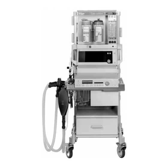
Page 108: Overall View Of The Machine
What's what Overall view of the machine Overall view of the machine Cato edition Gas and anaesthetic delivery Details on page 111 Monitor Details on page 110 Ventilator Details on page 109 Front Rear 1 Vapor connection 2 Master switch... -
Page 109: Operating Elements And Displays On Ventilator
What's what Operating elements and displays on ventilator Operating elements and displays on ventilator TEST SPONT SIMV IPPV IPPV PEEP 13 14 15 16 17 18 19 1 Pressure limiting valve (APL) with Manual/Spontaneous changeover 2 MAN/SPONT key for manual ventilation/spontaneous breathing 3 Bar graph of relative piston movement [%] 4 Indication of the set maximum pressure (P 5 Indication of the set tidal volume (V... -
Page 110: Operating Elements And Displays On Monitor
What's what Operating elements and displays on monitor Operating elements and displays on monitor Front panel of monitor: 1 Screen 2 Softkeys 3 Key for successively calling up the standard screen, data screen and trend screen 4 Key for calling up the standard screen 5 Red warning LED 6 Yellow caution/advisory LED 7 Keys for deactivating the alarm tone for two minutes and for reactivating it... -
Page 111: Operating Elements And Displays On The Gas And Anaesthetic Agent Measuring Tube Bank
Operating elements and displays on the gas and anaesthetic agent measuring tube bank Operating elements and displays on the gas and anaesthetic agent measuring tube bank Cato edition 1 Pressure gauge for O , AIR, N 2 Flow measuring tubes for O... -
Page 112: Elements On Breathing System
What's what Elements on breathing system Elements on breathing system 1 Plug-in connection for pressure measurement (P 2 Inspiration valve (with mount for O sensor, optional) 3 Inspiration port (ISO cone 22) 4 Quick-release coupling for measured gas return line 5 Expiration valve 6 Expiration port (ISO cone 22) with mount for flow sensor (screwed in) 7 Pressure limiting valve (APL) with pressure setting (turn), MAN/SPONT changeover (two-way switch) -
Page 113: Connections On The Rear Of The Monitor
8 Connection for sidestream CO / anaesthetic gas measurement (leads to water trap on the left-hand side of the Cato as seen from the front. The sampling line is connected to the water trap.) 9 Cooling air filter 10 Sensor for sidestream O... -
Page 114: Dimensions / Weight
A = 1480 mm A = 1415 mm 785 mm 785 mm 530 mm 530 mm 730 mm 730 mm 830 mm 760 mm 900 mm Weight Cato basic machine approx. 140 kg Cato with two Vapors and monitor approx. 180 kg... -
Page 115: Technical Data
Technical data Contents Technical data Contents Page General ....................116 Power supply ..................116 Ambient conditions ................116 Medical gas supply ................117 Breathing system .................. 117 Ventilator ....................117 Gas delivery ..................118 Monitor ....................118 Pressure measurement ..............118 Flow measurement ................ -
Page 116: General
The Article No. also specifies the equipment level of the machine. Weight ........: Cato basic machine approx. 140 kg Cato with two Vapors and monitor approx. 180 kg Dimensions.......: See dimensional drawings on page 114 Power supply Rated operating voltages ..: depending on... -
Page 117: Medical Gas Supply
Technical data Medical gas supply Breathing system Ventilator Medical gas supply Pneumatic connections....: Piped medical gas supply – O O, AIR Spare gas cylinders 11 L or 3 L for O and N O (optional) Anaesthetic gas scavenging Required pressures (piped supply): O : 2.7 to 5.5 bar O : 2.7 to 5.5 bar AIR : 2.7 to 5.5 bar... -
Page 118: Gas Delivery
Technical data Gas delivery Monitor Gas delivery Low-flow measuring tubes ..: (Calibrated for 20 °C, 1013 mbar) ± 10 % 0.02 to 0.5 L/min At minimum scale: + 20 %, – 10 % At minimum scale: ± 5 % ± 10 % 0.55 to 10.0 L/min At minimum scale: + 20 %, –... -
Page 119: O 2 , Co 2 And Anaesthetic Agent Measurement In Sidestream (Sampling)
Technical data Monitor , CO and anaesthetic agent measurement in sidestream (sampling) Sampling rate (selectable)..: 200 mL/min 60 mL/min measurement Range........: 5% to 100% by volume Resolution for FiO and FeO ...: 1% by volume Resolution for ∆O ....: 0.1% by volume ±3 % by vol. -
Page 120: Spo2 Measurement
Technical data Monitor Display range for sevoflurane ..: 0% to 11% by volume better than ± 0.2% by volume absolute Accuracy: 0 to 5% better than ± 0.4% by volume absolute 5 to 9% Resolution: 0.1 % by volume absolute Response time t ....: At 200 mL/min: 450 ms 10 ...90... -
Page 121: C-Lock™ Ecg Synchronization
Technical data Monitor Operating parameters C-Lock™ ECG synchronization (optional) Prerequisite for the ECG synchronization signal ..: Pos. pulse with > 4.5 V and > 10 ms duration to drive 2 mA. Max. permitted signal delay in relation to the current QRS complex ......: 40 ms Signal isolation from remaining electronics ....: Dielectric strength >... -
Page 123: Descriptions
Safety features of gas supply ..............136 Notes for reducing condensation ............136 Operation of the ceiling version ............137 Cato with ceiling suspension unit DVE 808X ......... 137 General requirements ................137 Connecting the Cato ceiling version ............138 Disconnecting the Cato ceiling version .......... -
Page 124: Flow Chart Of Self-Test
Descriptions Flow chart of self-test Flow chart of self-test Flow chart of self-test in ventilator Subsystem 3 Vapor Pneumatic interface Legend: Display in dialogue window of ventilator Indicated faults must be remedied, instructions and advisories observed. Information in dialogue window of ventilator Press rotary control Correspondingly numbered test blocks in VT window Test sequence *... - Page 125 Descriptions Flow chart of self-test Flow chart of self-test in ventilator (cont.) Test blocks: Control pressure test pneum.Interface? Service Nr. 118 Service Nr. 119 Service Nr. 115 Valve and roller diaphragm Valvedisk defect test Diaphragm defect > 5 L/min Subsystem 1 / 2 (IPPV) Subsyst.1/2 leak Leak <...
-
Page 126: Ventilation With Automatic Adjustment Of
– 3 mbar. In closed anaesthesia systems, anaesthetic gas cannot This shortage of fresh gas is signalled by the Cato and escape from the breathing system and no more fresh gas the piston pump stops in order to avoid a negative is delivered than is actually required by the patient. -
Page 127: Automatic Leakage Tests Ippv / Man
This leakage test identifies any leaks of relevance for in the compressible hose volume. This compressible automatic ventilation in subsystems 1 and 2 of the Cato volume must be known for ventilation to be effective. ventilation system. It also encompasses the breathing... -
Page 128: Notes On Setting Fresh Gas Flow
Descriptions Notes on setting the fresh gas flow Relationship between fresh gas flow and gas concentration Relationship between fresh gas flow and time constants Notes on setting the fresh gas flow Example for estimating the minimum fresh gas flow required in The fresh gas delivered must the steady state: –... -
Page 129: Principles Of Measurement
Descriptions Relationship between fresh gas flow and time constants Principles of measurement Rule of thumb for estimating the system response The current flowing through the cell is proportional to the over time: partial oxygen pressure in the gas mixture to be measured. - Page 130 Descriptions Principles of measurement Cross-sensitivity of the anaesthetic gas measurement: It contains about 47 mmHg water vapour. Up to the Measurement of the anaesthetic agent can be falsified by water trap, the gas cools down to approximately ambient vapours of organic substances (such as those contained temperature.
-
Page 131: Spo 2 Measurement
Descriptions Principles of measurement measurement The light absorption properties of oxygenated arterial 660 nm 920 nm blood (oxyhaemoglobin HbO ) differ from those of Infrared unsaturated venous blood (reduced haemoglobin Hb). 20 000 10 000 saturation is a logarithmic function of the irradiated 5 000 light intensity (Lambert-Beer's law). -
Page 132: Temperature Measurement
Descriptions Principles of measurement Definitions for »low-flow« and »minimal flow« anaesthesia Definitions for »low-flow« and »minimal flow« anaesthesia saturation 100% O saturation at 660 nm red Low-flow anaesthesia is performed with a fresh gas flow considerably below the minute ventilation. When setting such low fresh gas volumes, the anaesthetic gases must be returned to the patient via a semi-closed or closed rebreathing system. -
Page 133: Simv, Synchronised Intermittent Mandatory Ventilation
Descriptions SIMV SIMV Synchronized Intermittent Mandatory Ventilation Mixture of mechanical ventilation and spontaneous breathing. In SIMV mode, the patient can breathe spontaneously at specified regular intervals. Between these intervals, mandatory (i.e. automatically delivered) ventilation strokes ensure a minimum degree of ventilation. The mandatory ventilation strokes are the same as those for IPPV ventilation. - Page 134 Descriptions SIMV Trigger and spontaneous breathing times forSIMV mode: Trigger [sec] Spont Spont Trigger Example ∆T [sec] Maximum pause time Example: = 5 per minute =10 per minute IPPV ∆T = ––– – ––– = –––––––– – ––––––––– = 6 s 5 per min.
-
Page 135: S-Orc, O 2 Ratio Control
Descriptions Oxygen ratio control - S-ORC Oxygen ratio control - S-ORC To ensure an O concentration greater than 21% by volume in the fresh gas, the anaesthetic workstation has Flow tubes an O ratio control system (S-ORC = Sensitive Oxygen in the bank of Ratio Controller). -
Page 136: Safety Features Of Gas Supply
The greater the proportion of rebreathed gas (low-flow technique), the more moisture is produced. Replace the soda lime every day. Cato has been optimized for this low-flow technique: If the breathing system and piston cylinder unit cannot be replaced every day: –... -
Page 137: Operation Of The Ceiling Version
Depending on the DVE used and on the prevailing conditions, the Cato can be raised The main arm of the DVE 808X with Cato may have a off the floor to a height of approx. 60 cm. maximum length of 100 cm plus 50 cm for the extension It must not be moved across or positioned arm. -
Page 138: Connecting The Cato Ceiling Version
PPPPPP @@@@@@ PPPPPP @@@@@@ PPPPPP @@@@@@ PPPPPP on the DVE. Plug the gas withdrawal connectors into the corresponding withdrawal sockets. 6 Move Cato right up to the mount on the DVE. @@@@@@ PPPPPP @@@@@@ PPPPPP @@@@@@ PPPPPP @@@@@@ PPPPPP @@@@@@... -
Page 139: Disconnecting The Cato Ceiling Version
Cato and DVE light up when correctly positioned. The DVE can now be controlled (via the keypad in the handles of the Cato)! When Cato has been raised approx. 5 cm, the keypad on the DVE also becomes active in parallel to those on Cato's handles. -
Page 140: What To Do If Problems Arise
Briefly lower it onto the ground and pick it up again with the DVE. The mount may suffer damage in extreme cases! Call DrägerService if damage is suspected. Depending on how serious the damage is, the Cato may crash to the ground when raised again! -
Page 141: Abbreviations Used
Descriptions Abbreviations used Abbreviations used Abbreviation Significance Abbreviation Significance Compressed air for medical use IPPV Automatic ventilation mode: intermittent positive pressure ventilation Minute ventilation Light-emitting diode Adjustable pressure limitation LED display 7-segment display with light-emitting AW-Temp Inspiratory breathing gas temperature diodes Connection for breathing bag Man/Spont... -
Page 142: Symbols Used
Descriptions Symbols used Symbols used Symbol Significance ª Pulse rate Defibrillator strength < Lower alarm limit > Upper alarm limit Alarm monitoring inactive Cursor frame in menus Close menu, return to preceding menu level Changeover switch for standby and measuring modes Cyclic activation of basic pages Display standard page Suppress alarm tone for 2 minutes... -
Page 143: Index
Index Index bbreviations acterial filter, pressure measuring hose Acids, disinfectants Bacterial filter, secretion aspiration Adult mode Basic configuration, monitor Advisory messages Batteries, disposal (Messages, Cause and Remedy) Baud rate Advisory, concept / display Breathing system, assembling After use Breathing system, checking AIR changeover Breathing system, dismantling Alarm concept... - Page 144 Index Checking, reserve gas cylinders lements of the breathing system Checking, secretion aspiration Emergency Checking, soda lime 23, 45 Emergency ventilation bag Checking, supply of anaesthetic agent Emergency ventilation, gas failure Checking, Vapor End of operation Checking, water separator 44, 106 Environmental factors, Technical Data Checking, water traps 24, 44...
- Page 145 Index IPPV mode Monitor functions IPPV mode, selecting Monitor, activating Monitor, configuring in standby 13, 14, 110 Monitor, keys 13, 60, 112 eys, on monitor Keys, on ventilator 11, 109 Monitor, operating elements Kuhn system, paediatric Monitor, operation Monitor, structure 14, 110 Monitor, Technical data anguage, selecting...
- Page 146 Index Piston pump, assembly Self-test, flow chart Piston pump, dismantling Self-test, interrupting Piston pump, fitting Sensor, selecting, SpO measurement Piston pump, removal Shortage alarm, O Plethysmogram/SpO SIMV mode Pneumatic interface SIMV mode, selecting Power failure SIMV ventilation, description Power failure, manual ventilation Soda lime container, filling and fitting Power input Soda lime, changing during operation...
- Page 147 Index ninterruptible power supply Uses alves, fitting Valves, location of Vapor units 5, 6, 19, 22 Vapor, checking Vapor, interlock Vapor, plug-in adapter Vapor, safety fill Ventilation parameters, adjusting Ventilation, manual Ventilation, mechanical 39, 41 Ventilator messages (Messages, Cause and Remedy) Ventilator, operating controls Ventilator, Technical Data Voltage, current supply...
- Page 148 These Instructions for Use apply only to Cato edition with Serial No.: If no Serial No. has been filled in by Dräger these Instructions for Use are provided for general information only and are not intended for use with any specific machine or device.