Advertisement
Quick Links
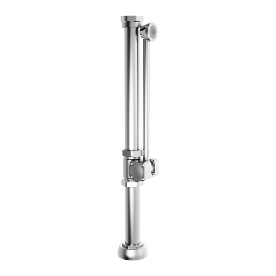
MANUAL FLUSH VALVE
with BEDPAN WASHER
For Use with 1-1/2" Top Spud Toilets
6047.860
Certified to comply with:
• ASSE 1037
• CSA B125.3
• ADA Compliant
© 2013 AS America, Inc.
M965403 REV. 1.1
NOTE TO INSTALLER: Please give this manual to the customer after installation.
To learn more about American Standard Faucets visit our website at: www.americanstandard.com
or U.S. customer's e-mail us at: faucetsupport@americanstandard.com
For Parts, Service, Warranty or other Assistance,
1-800-442-1902 (In Canada: 1-800-387-0369)
please call
6047.820
(In Toronto Area only: 1-905-3061093)
(In Toronto Area only: 1-905-3061093)
MODEL NUMBERS
6047.800
6047.815
6047.820
6047.860
6047.800
6047.815
Advertisement

Related Manuals for American Standard 6047.800


Summary of Contents for American Standard 6047.800
- Page 1 M965403 REV. 1.1 NOTE TO INSTALLER: Please give this manual to the customer after installation. To learn more about American Standard Faucets visit our website at: www.americanstandard.com or U.S. customer's e-mail us at: faucetsupport@americanstandard.com For Parts, Service, Warranty or other Assistance,...
- Page 2 M965403 REV. 1.1 NOTE TO INSTALLER: Please give this manual to the customer after installation. To learn more about American Standard Faucets visit our website at: www.americanstandard.com or U.S. customer's e-mail us at: faucetsupport@americanstandard.com For Parts, Service, Warranty or other Assistance,...
-
Page 3: Roughing-In Dimensions
Fig. 1 GENERAL DESCRIPTION: Roughing-in Dimensions FLUSH VALVE with BEDPAN WASHER For Use with Exposed Flushometer and 1-1/2" Top Spud Toilets 108mm-133mm FINISHED WALL FINISHED WALL (4-1/4" to 5-1/4") SUPPLY DN 25mm (1" I.P.S.) ADJUSTABLE 358mm 245mm (14-1/16") (9-5/8") 90˚ MAX. - Page 4 INSTALL TAILPIECE and DOWN Fig. 3 TUBE with VACUUM BREAKER; Fig. 3 1. Slide the COUPLING NUT (3) onto the TAIPIECE (4 or 4a). Place SEAL WASHER (2) with the tapered side facing down into the COUPLING NUT (3). 2. Thread and tighten COUPLING NUT (3) to DIVERTER ASSEMBLY (1).
- Page 5 INSTALL BEDPAN WASHER; Fig. 5 Fig. 5 1. Install BEDPAN WASHER ASSEMBLY (1) into SPUD ASSEMBLY (2) on fixture. Push the ASSEMBLY (1) down until the TAILPIECE (3) seats on the internal stop. Do not fully tighted SPUD COUPLING NUT (4). 2.
- Page 6 INSTALL FLUSH VALVE; Fig. 8 Fig. 8 & 8a 1. As shown in Fig. 8, insert the side INLET FLANGE (1) on the FLUSH VALVE (2) into the SUPPLY STOP (3). Lubricate the INLET FLANGE O-RING (4) with water if necessary.
- Page 7 FLUSH OUT SUPPLY LINES; Fig. 10 Fig. 10 1. Remove COVER (1) from SUPPLY STOP (2). Make sure supply stop is closed. 2. Remove FLUSH VALVE CAP (3). Pull out PISTON (4). Replace FLUSH VALVE CAP (3) and tighten. 3. With a flat blade screwdriver open SUPPLY STOP (2). to flush line of any debris or sediment.
- Page 8 TEST INSTALLAED BEDPAN Fig. 13 WASHER; Fig. 13 1. Check alignment of FLUSH VALVE (1) and DIVERTER VALVE ASSEMBLY (2) and fully tighten all connections. 2. Push the DIVERTER ARM and SPRAY (3) down, parallel to the toilet rim. Flush the toilet to activate the SPRAY (4).