Advertisement
Quick Links
Computer System Requirements
Supported Systems
Operating System: Windows 7/8/10
l
USB:USB 2.0 and later
l
Minimum Requirements
Processor: Core i5 at 2.7 GHz
l
RAM: 4 GB
l
Free Hard Disk Space on C: drive: 20 GB
l
1. Hardware Setup - Part 1
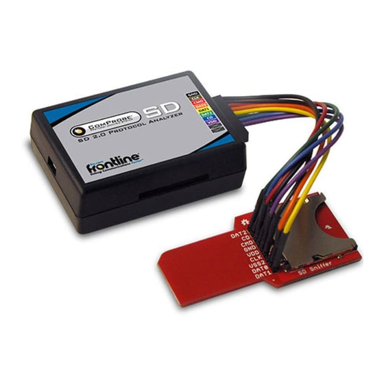
Once you have installed the software and the device drivers, the next step is to set up the hardware.
Provided with the Frontline SD hardware is one of two Secure Digital (SD) Input/Output (IO) adapters: 1) the standard SD card adapter,
and 2) the micro SD card adapter. Provided with each is a cable that must be connected to the adapter prior to the connecting the
adapter to the Frontline SD hardware. The following tables lists the Frontline SD Hardware pinout, with corresponding cable color-code
and the adapter pinout. In addition the table shows the pin designation for the SD 4-bit and 1-bit high-speed mode and the SPI mode.
Pin
1
CD/DAT3
2
CMD
3
VSS1
4
VDD
5
CLK
6
VSS2
7
DAT0
8
DAT1
9
DAT2
Frontline Technical Support: Phone +1-434-984-4500 or email tech_support@fte.com
Table 1 - SDIO Pinout
SD 4-bit Mode
Data Line 3
Command Line
Ground
Supply Voltage
Clock
Ground
Data Line 0
Data Line 1/Interrupt
Data Line 2/ Read Wait
Install Software
From Download: Download the latest ComProbe installer
l
from FTE.com. Once downloaded, double-click the
installer and follow the directions.
http://www.fte.com/sd-soft
SD 1-bit Mode
-
-
CMD
Command Line
VSS1
Ground
VDD
Supply Voltage
CLK
Clock
VSS2
Ground
DATA
Data Line
IRQ
Interrupt
RW
Read Wait
Quick Start
Guide
SPI Mode
CS
Card Select
DI
Data Input
VSS1 Ground
VDD
Supply Voltage
SCLK Clock
VSS2 Gound
DO
Data Output
IRQ
Interrupt
-
-
Advertisement

Subscribe to Our Youtube Channel
Related Manuals for Teledyne Lecroy Frontline SD


Summary of Contents for Teledyne Lecroy Frontline SD
-
Page 1: Quick Start
Once you have installed the software and the device drivers, the next step is to set up the hardware. Provided with the Frontline SD hardware is one of two Secure Digital (SD) Input/Output (IO) adapters: 1) the standard SD card adapter, and 2) the micro SD card adapter. - Page 2 Standard SD Adapter and Cable Micro SD Adapter and Cable Table 2 - Frontline SD Adapter Wiring List Frontline Adapter Cable Wire Standard Adapter Micro Adapter Hardware Color Pin/Label Pin/Label Black 4/GND 4/GND Brown 7/CLK 6/CLK 3/CMD 3/CMD DAT0 Orange...
- Page 3 Connect Cable to Adapter 1. Refer to the SDIO Pinout table and the Frontline SD Adapter Wiring list for the SD mode and adapter you will be using. 2. Identify the wire color associated with the pin on the adaper for the appropriate mode.
- Page 4 2. Selecting Data Capture Method Now that the test devices are on, the SD hardware properly connected to the PC, the next step is to open the Frontline software. Open "Frontline (version #)” from the Start menu or from the Desktop folder (2).
- Page 5 6. Hardware Setup - Part 2 You have already seen how to connect the SD card adapter to the Frontline SD hardware and the USB cable to the analysis PC. Now let's continue with the rest of the hardware setup.
- Page 6 Device Under Test Connection 1. Insert the Device under Test (DUT), such as a micro SD MMC memory card into the slot on the IC board (). Device Under Test Connection Setup 2. Insert the other end of the IC board into the SD slot on the test PC (). Plugging IC Board to the Analysis PC That is the complete hardware setup if you are using a memory card.
- Page 7 This quick start guide provides sufficient information to begin the data capture. Detailed hardware and software information is contained in the ComProbe SD User Manual. The manual is available on FTE.com. © 2017 Teledyne LeCroy, Inc. The Bluetooth SIG owns the Bluetooth word mark and logos, and use of such marks is under license.
Need help?
Do you have a question about the Frontline SD and is the answer not in the manual?
Questions and answers