
Related Manuals for turck BL20-E-4IOL


Summary of Contents for turck BL20-E-4IOL
- Page 1 Your Global Automation Partner BL…-4IOL IO-Link Master Modules for BL20 and BL67 Operating instructions...
- Page 2 Hans Turck GmbH & Co. KG | T +49 208 4952-0 | F +49 208 4952-264 | more@turck.com | www.turck.com...
- Page 3 4.5.1 BL67-wiring diagram 4.5.2 BL20-wiring diagram Function description Process image 5.1.1 Process input data 5.1.2 Process output data 5.1.3 Process Data Mapping Parameters 5.2.1 Parameters for BL20-E-4IOL and BL67-4IOL 5.2.2 Parameters for BL20-E-4IOL-10 5.2.3 Special DTM functions V01.00 | 2016/12...
- Page 4 8.2.1 Configuration of the IO-Link master 8.2.2 Configuration of the IO-Link ports Use the IO_LINK_DEVICE function block in TIA Portal 8.3.1 Example accesses with IO_LINK_DEVICE Hans Turck GmbH & Co. KG | T +49 208 4952-0 | F +49 208 4952-264 | more@turck.com | www.turck.com...
- Page 5 CODESYS 2.3 (for programmable gateways): IOL_CALL Example project 9.1.1 Used Hardware 9.1.2 Used Software Configuration in CODESYS 9.2.1 Prerequisites 9.2.2 Configuration of the IO-Link ports Usage of the function block in CODESYS 9.3.1 Example accesses with IOL_CALL Appendix 10.1 Start-up: IO-Link-Device with IO-Link V1.0 10.2 Start-up: IO-Link-Device with IO-Link V1.1 10.3...
- Page 6 Hans Turck GmbH & Co. KG | T +49 208 4952-0 | F +49 208 4952-264 | more@turck.com | www.turck.com...
-
Page 7: About These Instructions
About these instructions These operating instructions describe the structure, functions and the use of the product and will help you to operate the product as intended. Read these instructions carefully before using the product. This is to avoid possible damage to persons, property or the device. Retain the instructions for future use during the service life of the product. -
Page 8: Additional Documents
Hans Turck GmbH & Co. KG | T +49 208 4952-0 | F +49 208 4952-264 | more@turck.com | www.turck.com... -
Page 9: Notes On The Product
45472 Muelheim an der Ruhr Germany Turck supports you with your projects, from initial analysis to the commissioning of your applica- tion. The Turck product database contains software tools for programming, configuration or com- missioning, data sheets and CAD files in numerous export formats. You can access the product data- base at the following address:www.turck.de/produkte... - Page 10 Notes on the Product Hans Turck GmbH & Co. KG | T +49 208 4952-0 | F +49 208 4952-264 | more@turck.com | www.turck.com...
-
Page 11: For Your Safety
The product is designed according to state-of-the-art technology. However, residual risks still exist. Observe the following warnings and safety notices to prevent damage to persons and property. Turck accepts no liability for damage caused by failure to observe these warning and safety notices. Intended Use These devices are designed solely for use in industrial areas. - Page 12 For Your Safety Hans Turck GmbH & Co. KG | T +49 208 4952-0 | F +49 208 4952-264 | more@turck.com | www.turck.com...
-
Page 13: Product Description
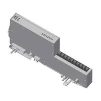
Product description The Turck IO-Link master modules BL20-E-4IOL(-10) or respectively BL67-4IOL are technology mod- ules of the modular I/O-systems BL20 and BL67. They can be connected to several fieldbus systems and Ethernet protocols via the respective gateways. The IO-Link module provides 4 IO-Link master channels and 4 universal digital channels (PNP). -
Page 14: Compatible Bl20 Gateways, Codessys Programmable
V1.27 PROFIBUS-DP BL67-GW-DPV1 6827232 V5.02 CANopen BL67-GW-CO 6827200 V7.18 DeviceNet™ BL67-GW-EN 6827183 V3.1.0.0 Multi protocol BL67-GW-EN 6827214 Hans Turck GmbH & Co. KG | T +49 208 4952-0 | F +49 208 4952-264 | more@turck.com | www.turck.com... -
Page 15: Technical Data
Technical data NOTE For all technical data that are specific for the product lines, please read the I/O-manuals of the respective product family (BL20: D300717 and BL67: D300529). BL20-E-4IOL/ BL67-4IOL BL20-E-4IOL-10 Power supply Module bus current I Max. < 40 mA Max. - Page 16 3- or 4-wire (depending on the 3- or 4-wire (depending on the application), unshielded application), unshielded Hans Turck GmbH & Co. KG | T +49 208 4952-0 | F +49 208 4952-264 | more@turck.com | www.turck.com...
-
Page 17: Connecting
Connecting ATTENTION! Wrong supply of IO-Link devices Damage to the electronics The IO-Link devices must only be supplied with the voltage provided at the supply ter- minals BL67: V (pin 1 and 3) sens BL20: U (terminal 9 and 10) 4.5.1 BL67-wiring diagram Base module... - Page 18 The IO-Link devices must be supplied with the same potential as U of the gateway or the BR/PF module (if used). Hans Turck GmbH & Co. KG | T +49 208 4952-0 | F +49 208 4952-264 | more@turck.com | www.turck.com...
-
Page 19: Function Description
2 byte control data) in total for all 4 for channels. The process image can be adapted application-specifically via the module's parameterization, see Process Data Mapping (Seite 19). Device Process input data Process output data BL20-E-4IOL 16 byte 16 byte BL67-4IOL 16 byte 16 byte BL20-E-4IOL-10... -
Page 20: Process Output Data
It depends on the parameterization of the channel which data are shown in which order (see parameter "pro- cess output data length" and "process output data mapping"). Hans Turck GmbH & Co. KG | T +49 208 4952-0 | F +49 208 4952-264 | more@turck.com | www.turck.com... -
Page 21: Process Data Mapping
5.1.3 Process Data Mapping The mapping of process data can be adapted application-specifically via the master's parameteriza- tion. Depending on the used fieldbus, it can be necessary to swap process data word-wise, double word- wise or completely in order to align them to the data structure in the PLC. The process data mapping is determined channel by channel through the parameters "process input data mapping"... -
Page 22: Parameters
The device remains in the safe state (Pre-Operate). Parameters and diagnostic information can be read and respectively written. Hans Turck GmbH & Co. KG | T +49 208 4952-0 | F +49 208 4952-264 | more@turck.com | www.turck.com... - Page 23 Name Meaning Value 0100 DI (with parameter Pin 4 (BL67) of the respective connector or the respective terminal access) 1/2/3 or 4 (BL20) is generally operated as simple digital input. However, an acyclic parameter access from the PLC or the DTM is possible.
- Page 24 If the process data are invalid, a respective diagnostic message is generated. No diagnostics Invalid process data do not cause a diagnostic message. generated Hans Turck GmbH & Co. KG | T +49 208 4952-0 | F +49 208 4952-264 | more@turck.com | www.turck.com...
- Page 25 Name Meaning Value Deactivate diagnostics Influences the sending of IO-Link-Events from the master to the fieldbus. Depending on the parameteriza- tion, the master transmits Events based on their priority to the fieldbus or not. The master transmits all IO-Link Events to the fieldbus. Notifications The master transmits all IO-Link Events to the fieldbus except for IO-Link notifications.
-
Page 26: Parameters For Bl20-E-4Iol-10
Assignment similar to port 1 Channel 3 22…32 Assignment similar to port 1 Channel 4 33…43 Assignment similar to port 1 Hans Turck GmbH & Co. KG | T +49 208 4952-0 | F +49 208 4952-264 | more@turck.com | www.turck.com... - Page 27 The default values are written in bold Name Meaning Value Operation mode IO-Link without The respective terminal 1/2/3 or 4 is operated in IO-Link mode. validation The master does not check if the connected device matches the configured one IO-Link with The respective terminal 1/2/3 or 4 is operated in IO-Link mode.
- Page 28 Settable in steps of 0.8 or 1.6 ms. 11001111 (see Values for the parameter "cycle time" [ms] (Seite 29)) (0×01 - 0×BF) Revision Hans Turck GmbH & Co. KG | T +49 208 4952-0 | F +49 208 4952-264 | more@turck.com | www.turck.com...
- Page 29 Name Meaning Value Automatic The Master defines the IO-Link-revision automatically. V1.0 IO-Link-Revision V 1.0 is used. Process input data invalid Diagnostics generated If the process data are invalid, a respective diagnostic message is generated. No diagnostics Invalid process data do not cause a diagnostic message. generated Deactivate diagnostics Influences the sending of IO-Link-Events from the master to the fieldbus.
- Page 30 Device ID of the connected IO-Link device for the port configura- tion check Value range: 0…FFFFFF (24 bit, Little Endian format) Hans Turck GmbH & Co. KG | T +49 208 4952-0 | F +49 208 4952-264 | more@turck.com | www.turck.com...
- Page 31 Values for the parameter "cycle time" [ms] Time Value Time Value Time Value Time Value Time Value Time Value auto 15.2 0×56 30.4 0×7C 59.2 0×91 89.6 0×A4 0×B7 0×08 0×58 31.2 0×7E 60.8 0×92 91.2 0×A5 121.6 0×B8 0×10 16.8 0×5A 0×80...
-
Page 32: Special Dtm Functions
The data of the connected device/ the connected devices are read-in by the master. Factory settings The master is set back to its factory settings. Hans Turck GmbH & Co. KG | T +49 208 4952-0 | F +49 208 4952-264 | more@turck.com | www.turck.com... -
Page 33: Diagnostic And Status Messages
Diagnostic and status messages 5.3.1 LED displays This module provides the following LEDs for status displays: DIA: Monitors the module status Channel LEDs – BL67: Status display for the IO-Link- or respectively DI-channels at Pin 4 of the M12 connectors 0 - 3: Status display for the XSG-channels at Pin 2 of the M12 connectors 4 - 7:... - Page 34 Status of channel x = „1“ (ON) resp. 5 - 8 blinking, Short circuit at output of the respec- (BL20) 0.5 Hz tive channel Hans Turck GmbH & Co. KG | T +49 208 4952-0 | F +49 208 4952-264 | more@turck.com | www.turck.com...
-
Page 35: Diagnostic Data
5.3.2 Diagnostic data There are different types of diagnostic messages, master and device diagnostics. The „PD " diagnostic (process data invalid) can be sent from both devices, IO-Link master or IO- invalid Link device. Master diagnostics The master sends reports problems within the IO-Link communication. Device diagnostics The device diagnostics map the IO-Link Event codes (according to the IO-Link specification) sent from the IO-Link devices... - Page 36 Hardware error General hardware error or device malfunction. EVTD2 Out-of-specification events An Out-of-Specification Event in accordance with the IO-Link specification occurred. Hans Turck GmbH & Co. KG | T +49 208 4952-0 | F +49 208 4952-264 | more@turck.com | www.turck.com...
- Page 37 Meaning Remedy EVTD1 Maintenance events A Maintenance Event in accordance with the IO-Link specification occurred, maintenance nec- essary. Param Parameterization error The connected device reports a parameterization error (loss of parameters, no parameter ini- tialization, etc.). OTemp Overtemperature Temperature diagnostic message at the connected device. UFLW Lower limit value underrun The process value lies under the parameterized measurement range or the chosen measure-...
-
Page 38: The Principle Of The Data Storage Mechanism
0 = no changes in the device's parameter set 1 = changes in the device's parameter set (e. g. via DTM, at the device, etc.) Hans Turck GmbH & Co. KG | T +49 208 4952-0 | F +49 208 4952-264 | more@turck.com | www.turck.com... -
Page 39: Parameters: Data Storage Mode = Activated
5.4.2 Parameters: Data storage mode = activated The synchronization of the parameter sets is bidirectional. The most actual data set (master or device) is valid: This means: – The data set in the device is actual, if DS_UPLOAD_FLAG = 1 –... -
Page 40: Parameters: Data Storage Mode = Read In
The status of the DS_UPLOAD_FLAG is ignored. IO-Link-Master IO-Link-Device Para. IOLD = parameter data of the IO-Link device Fig. 5: “Data storage mode" = read in Hans Turck GmbH & Co. KG | T +49 208 4952-0 | F +49 208 4952-264 | more@turck.com | www.turck.com... -
Page 41: Parameters: Data Storage Mode = Overwrite
5.4.4 Parameters: Data storage mode = overwrite The data set in the master is alwrtrtzjays the reference data set. The synchronization of the parameter sets is unidirectional towards to the device. The status of the DS_UPLOAD_FLAG is ignored. IO-Link-Master IO-Link-Device Para. -
Page 42: Subindex 64: Master Port Validation Configuration
2 byte Unsigned 16 DEVICE_ID 4 byte Unsigned 32 FUNCTION_ID 2 byte Unsigned 16 Value: 0 SERIAL_NUMBER 16 byte String Hans Turck GmbH & Co. KG | T +49 208 4952-0 | F +49 208 4952-264 | more@turck.com | www.turck.com... -
Page 43: Subindex 65: Io-Link Events
Content Size Format Comment IOL3 VENDOR_ID 2 byte Unsigned 16 DEVICE_ID 4 byte Unsigned 32 FUNCTION_ID 2 byte Unsigned 16 Value: 0 SERIAL_NUMBER 16 byte String IOL3 VENDOR_ID 2 byte Unsigned 16 DEVICE_ID 4 byte Unsigned 32 FUNCTION_ID 2 byte Unsigned 16 Value: 0 SERIAL_NUMBER... - Page 44 Event Code sent. Event Code low byte Qualifier see byte 1 - 4 Port Event Code high byte Event Code low byte Hans Turck GmbH & Co. KG | T +49 208 4952-0 | F +49 208 4952-264 | more@turck.com | www.turck.com...
-
Page 45: Subindex 66: Set Default Parameterization
Subindex 66: Set Default Parameterization Entity_ IO-Link Read Length Description Port subindex Write 4 byte Writing this object sets the IO-Link master back to factory settings. Any parameter set- ting and configuration is overwritten. The data storage buffer is deleted as well. Structure of the reset command: Byte 3 Byte 2... - Page 46 Cycle time UINT8 Cycle time of the connected device Port 2 Structure similar to port 1 Port 3 Port 4 Hans Turck GmbH & Co. KG | T +49 208 4952-0 | F +49 208 4952-264 | more@turck.com | www.turck.com...
-
Page 47: Subindex 69: Extended Port Diagnostics
Subindex 69: Extended Port Diagnostics Entity_ IO-Link Read Length Description Port subindex Write max. 8 byte This object serves for reading the Extended Port Diagnostics. Structure of the Extended Port Diagnostics: Bit 7 Bit 6 Bit 5 Bit 4 Bit 3 Bit 2 Bit 1 Bit 0... -
Page 48: Device Status
Adapt the master parameterization (see parameter Mode (Seite 20)) Device Status Value Meaning Device works correctly Maintenance Event Out-of-Specification Event Functional check Error 5-255 reserved Hans Turck GmbH & Co. KG | T +49 208 4952-0 | F +49 208 4952-264 | more@turck.com | www.turck.com... -
Page 49: The Io-Link Function Block: Iol_Call
The IO-Link function block: IOL_CALL General The IO-Link function block IOL_CALL is specified in the IO-Link specification "IO-Link Integration Part 1- Technical Specification for PROFIBUS and PROFINET“". NOTE Depending on the PLC manufacturer, the IO-Link CALL function block can differ from the specification (for example in the representation or the use of variables). -
Page 50: Turck Io-Link Function Blocks
BL20-E-GW-EN (with 4IOL master module) BL67-GW-EN (with 4IOL master module) TBEN-S2-4IOL TBEN-Lx-8IOL BLCEN-xxxx-4IOL FEN20-4IOL Hans Turck GmbH & Co. KG | T +49 208 4952-0 | F +49 208 4952-264 | more@turck.com | www.turck.com... -
Page 51: Input Variables
6.3.1 IO-Link CALL (Turck) Input variables Variable Data type Meaning xREQ BOOL A rising edge triggers the send command. Address assignement of The address assignment of the IO-Link master module depends on the fieldbus/ Address the IO-Link master mod- Ethernet protocol used and varies depending on the module used, see... -
Page 52: Output Variables
Interface and System"), which concern the communication between IO-Link master and connected devices. see IOL_STATUS (Seite 52) iLEN Length of the data which were read. Hans Turck GmbH & Co. KG | T +49 208 4952-0 | F +49 208 4952-264 | more@turck.com | www.turck.com... -
Page 53: Status - Communication Error Status
6.3.2 STATUS - communication error status The status of the acyclic communication contains 4 byte and is structured as follows: Byte 3 Byte 2 Byte 1 Byte 0 0×80 Manufacturer specific Vendor specific identi- Specifies the error as an identifier (not always Error code fier (not always applica- error of acyclic commu-... -
Page 54: Iol_Status
Application error in the device 0×8011 IDX_NOTAVAIL Index not available 0×8012 SUBIDX_NOTAVAIL Sub index not available 0×8020 SERV_NOTAVAIL Service temporarily not available Hans Turck GmbH & Co. KG | T +49 208 4952-0 | F +49 208 4952-264 | more@turck.com | www.turck.com... - Page 55 Error code Name Meaning acc. to spec. 0×8021 SERV_NOTAVAIL_LOCCTRL Service temporarily not available, device is busy (e. g. teaching or parameterization of the device at the device active) 0×8022 SERV_NOTAVAIL_DEVCTRL Service temporarily not available, device is busy (e. g. teaching or parameterization of the device via DTM/ PLC etc.
- Page 56 The IO-Link function block: IOL_CALL Hans Turck GmbH & Co. KG | T +49 208 4952-0 | F +49 208 4952-264 | more@turck.com | www.turck.com...
-
Page 57: Step 7 (Profibus-Dp/Profinet): Iol_Call (Fb102)
– IO-Link Master BL20-E-4IOL with IO-Link port 1: Turck temperature sensor,TS-500-LUUPN8X-H1141 IO-Link port 2: not used IO-Link port 3: not used IO-Link port 4: Turck I/O hub, TBIL-M1-16DIP 7.1.2 Used Software SIMATIC Manager, Step 7, version 5.5, SP2 2018/10... -
Page 58: Configuration
Step 7 (PROFIBUS-DP/PROFINET): IOL_CALL (FB102) Configuration 7.2.1 Configuration of the IO-Link master Fig. 9: Configuration of the IO-Link master Hans Turck GmbH & Co. KG | T +49 208 4952-0 | F +49 208 4952-264 | more@turck.com | www.turck.com... -
Page 59: Configuration Of The Io-Link Ports
7.2.2 Configuration of the IO-Link ports The 4 ports of the IO-Link master can be operated in IO-Link mode with different configuration as well as in DI mode (see also parameter Operation mode (Seite 25)). Fig. 10: Configuration of the IO-Link ports ... - Page 60 Parameters (Seite – Device: Turck I/O hub, TBIL-M1-16DIP, 2 byte process data Fig. 11: Configuration of the IO-Link ports (example project) Hans Turck GmbH & Co. KG | T +49 208 4952-0 | F +49 208 4952-264 | more@turck.com | www.turck.com...
-
Page 61: Usage Of The Function Block In Step 7
Usage of the function block in Step 7 Kapitel 6 contains a general description of the function block and its in and output variables. IO-Link function block: IOL_CALL. Fig. 12: Example of Siemens FB IO-Link-CALL (FB102) in OB1 2018/10... -
Page 62: Example Accesses With Iol_Call
The IO-Link device is connected to port 4. IOL_INDEX 0×12 Index for product name Fig. 13: Input variables for read access Hans Turck GmbH & Co. KG | T +49 208 4952-0 | F +49 208 4952-264 | more@turck.com | www.turck.com... - Page 63 Activate the read access via a rising edge at "REQ": Fig. 14: Activating the read access In this example, the result of this request can be seen in the process data table VAT "Sensor 1". Fig. 15: Process data of the sensor 2018/10...
- Page 64 HW Config CAP (INDEX_CAP) Function block instance PORT (ENTITY_PORT) The IO-Link device is connected to port 1. Hans Turck GmbH & Co. KG | T +49 208 4952-0 | F +49 208 4952-264 | more@turck.com | www.turck.com...
- Page 65 Variable Value Meaning IOL_INDEX 0×55 Index for "Measured value update time/rotating/ disabling a display", see above. LEN_READ 1 byte is written. Fig. 17: Input variables for write access The value to be written (0x05) is entered as control value in the variable table (VAT) and is then written.
- Page 66 Fig. 19: Activating the write access The sensor's display is now rotated for about 180°, the update time is set to 600 ms. Hans Turck GmbH & Co. KG | T +49 208 4952-0 | F +49 208 4952-264 | more@turck.com | www.turck.com...
-
Page 67: Used Hardware
BL67-GW-EN with IO-Link master module BL67-4IOL at slot 1 of the BL67 station IO-Link device at BL67-4IOL: Port 1 Turck temperature sensor, TS-530-LI2UPN8X-..., IO-Link V1.0 Port 2 Port 3 Port 4 Turck I/O hub: TBIL-M1-16DXP, IO-Link V1.1 8.1.2 Used Software ... -
Page 68: Hardware Configuration
It is reasonable to set the "process input data length" and "process output data length" to 0, in order not to block bytes with digital data in the process data mapping on the fieldbus. Hans Turck GmbH & Co. KG | T +49 208 4952-0 | F +49 208 4952-264 | more@turck.com | www.turck.com... -
Page 69: Configuration Of The Io-Link Ports
IO-Link without validation Every IO-Link device will be accepted as exchange device in case – of a device exchange, see also Parameters (Seite 20). – Device: Turck temperature sensor, TS-500-LUUPN8X-H1141, 2 byte process data Port 2 and port 3: – configured as DI Port 4: IO-Link without validation Every IO-Link device will be accepted as exchange device i case... -
Page 70: Use The Io_Link_Device Function Block In Tia Portal
In TIA-Portal V13, the old IOL_CALL function block can be used to access these functions. Siemens provides it as “Archive.zip” for TIA Portal users underhttps://support.indus- try.siemens.com. Hans Turck GmbH & Co. KG | T +49 208 4952-0 | F +49 208 4952-264 | more@turck.com | www.turck.com... -
Page 71: Example Accesses With Io_Link_Device
8.3.1 Example accesses with IO_LINK_DEVICE In this example, the watch table "Sensor1" serves to visualize the procedure of the read and write access via IO_LINK_DEVICE. The assignment of the SPDU-indices of IO-Link devices can be found in the respective device docu- mentation. - Page 72 The IO-Link device is connected to port 4. IOL_INDEX 0x12 Index for product name Fig. 24: Input variables for the read access Hans Turck GmbH & Co. KG | T +49 208 4952-0 | F +49 208 4952-264 | more@turck.com | www.turck.com...
- Page 73 Activate the read access via a rising edge at "REQ". Fig. 25: Activating the read access 2018/10...
- Page 74 In this example, the result of this request can be seen in the watch table (row 19 and following) in the "IO-Link Record". Fig. 26: Process data of the sensor Hans Turck GmbH & Co. KG | T +49 208 4952-0 | F +49 208 4952-264 | more@turck.com | www.turck.com...
- Page 75 Write access Changing the parameter "Measured value update time/rotating/disabling a display" (index 55) to the value 0x05 (600 ms measured value update time, display rotated by 180°) for the TURCK tem- perature sensor TS-500-LUUPN8X-H1141 at IO-Link port 1. Fig. 27: Extract from the documentation for Turck temperature sensors ...
- Page 76 Set the variable “RD_WR Sensor 1” to TRUE for activating the write access. Fig. 28: Input variables for write access Hans Turck GmbH & Co. KG | T +49 208 4952-0 | F +49 208 4952-264 | more@turck.com | www.turck.com...
- Page 77 Set the value to be written (0x05) via the first word of "IO-Link Record" in the watch table. Fig. 29: Control value for index 0×55 2018/10...
- Page 78 Fig. 30: Activating the write access The sensor's display is now rotated for about 180°, the update time is set to 600 ms. Hans Turck GmbH & Co. KG | T +49 208 4952-0 | F +49 208 4952-264 | more@turck.com | www.turck.com...
-
Page 79: Codesys 2.3 (For Programmable Gateways): Iol_Call
Used Hardware TURCK BL67-PG-EN-V3 (firmware version V1.1.5.0) – IO-Link Master BL67-4IOL with IO-Link port 1: Turck temperature sensor, TS-500-LUUPN8X-H1141 IO-Link port 2: not used IO-Link port 3: not used IO-Link port 4: Turck I/O hub, TBIL-M1-16DIP 9.1.2 Used Software ... -
Page 80: Configuration In Codesys
It is reasonable to set the "process input data length" and "process output data length" to 0, in order not to block bytes with digital data in the process data mapping on the fieldbus. Hans Turck GmbH & Co. KG | T +49 208 4952-0 | F +49 208 4952-264 | more@turck.com | www.turck.com... - Page 81 IO-Link with identical device Only an identical exchange device is accepted in case of a – device exchange (check of vendor-ID, device-ID, etc., see Parameters (Seite 20). – Device: Turck temperature sensor, TS-500-LUUPN8X-H1141, 2 byte process data Port 1 and Port 2: – configured as DI Port 3: IO-Link without validation ...
-
Page 82: Usage Of The Function Block In Codesys
IO-Link function block: IOL_CALL. The IOL-CALL-FB is part of the Turck library „IO-Link CALL LocalIO“. Fig. 33: Turck IO-Link call in CODESYS Hans Turck GmbH & Co. KG | T +49 208 4952-0 | F +49 208 4952-264 | more@turck.com | www.turck.com... -
Page 83: Example Accesses With Iol_Call
The assignment of the sub indices of IO-Link devices can be found in the respective device docu- mentation. read access Reading out the product name (product name, index 0x18) of the Turck IO-Link I/O-hub TBIL-M1- 16DIP at IO-Link port 1. Write the input variables of the function block as follows: Variable Value (dec.) - Page 84 In this example, the result of this request can be found in the data array „Record_IOL_Data“: TBIL-M1-16DIP Fig. 36: Process data of the sensor Hans Turck GmbH & Co. KG | T +49 208 4952-0 | F +49 208 4952-264 | more@turck.com | www.turck.com...
- Page 85 Write access Changing the parameter "Measured value update time/rotating/disabling a display" (index 55) to the value 0x05 (600 ms measured value update time, display rotated by 180°) for the Turck tempera- ture sensor TS-500-LUUPN8X-H1141 at IO-Link port 1. Fig. 37: Extract from the documentation for Turck temperature sensors ...
- Page 86 For the write access, define the exact length if the data to be written. Fig. 38: Input variables for write access Hans Turck GmbH & Co. KG | T +49 208 4952-0 | F +49 208 4952-264 | more@turck.com | www.turck.com...
- Page 87 The value to be written ("05", s. 83) is entered in the data array „Record_IOL_Data“ and is then written. Fig. 39: Input value for write access 2018/10...
- Page 88 Fig. 40: Activating the write access The sensor's display is now rotated for about 180°, the update time is set to 600 ms. Hans Turck GmbH & Co. KG | T +49 208 4952-0 | F +49 208 4952-264 | more@turck.com | www.turck.com...
-
Page 89: Appendix
10 Appendix 10.1 Start-up: IO-Link-Device with IO-Link V1.0 IO-Link devices in accordance with IO-Link specification V1.0 do not support data storage. This means, that the parameter "Data storage mode" has to be set to "deactivated/, clear" if an IO-Link V1.0 devices is used. Fig. -
Page 90: Start-Up Problems - Frequently Failure Causes
To do so, set parameter "Process input data invalid (Seite 22)" to "no diagnostic generated". Hans Turck GmbH & Co. KG | T +49 208 4952-0 | F +49 208 4952-264 | more@turck.com | www.turck.com... - Page 91 30 subsidiaries and over 60 representations worldwide! D301333 | 2018/10 *D301333* www.turck.com...
Need help?
Do you have a question about the BL20-E-4IOL and is the answer not in the manual?
Questions and answers