Table of Contents
Advertisement
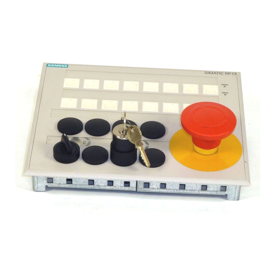
SIMATIC HMI
PP7, PP17-I, PP17-II
Push Button Panels
Equipment Manual
6AV3991–1CA00–0AB0
Release 06/98
www.gkbpx.com
Preface, Contents
Product Description
Starting Up the Push Button
Panel
Control Bit Assignment
Installation
Unit Description PP7
Unit Description PP17-I
Unit Description PP17-II
Attach Labeling Strips
Spare Parts
Technical Data
System Messages
Hardware Test
Siemens Worldwide
Index
该文档是极速PDF编辑器生成,
如果想去掉该提示,请访问并下载:
http://www.jisupdfeditor.com/
1
2
3
4
5
6
7
8
9
A
B
C
D
Advertisement
Table of Contents

Related Manuals for Siemens SIMATIC PP7


Summary of Contents for Siemens SIMATIC PP7
- Page 1 SIMATIC HMI Control Bit Assignment PP7, PP17-I, PP17-II Installation Push Button Panels Unit Description PP7 Equipment Manual Unit Description PP17-I Unit Description PP17-II Attach Labeling Strips Spare Parts Technical Data System Messages Hardware Test Siemens Worldwide Index 6AV3991–1CA00–0AB0 Release 06/98...
- Page 2 Trademarks SIMATIC is a registered trademark of Siemens AG. Some of the other designations used in these documents are also registered trademarks; the owner’s rights may be violated if they are used be third parties for their own purposes.
-
Page 3: Release
Technical data, system messages, hardware test Further support Please address technical questions to your local Siemens partners in the subsid- iaries and branch offices responsible for your area. Refer to Appendix D of this equipment manual for a list of addresses. -
Page 4: Release
Fax: +49 (911) 895-7002 Fax: +1 423 461-2231 Fax: +65 740-7001 E-mail: simatic.support@ E-mail: simatic.hotline@ E-mail: simatic@ nbgm.siemens.de sea.siemens.com singnet.com.sg SIMATIC Premium Hotline (chargeable, SIMATIC Card required) Times: Mon-Fri 0:00 to 24:00 Tel.: +49 (911) 895-7777 Fax: +49 (911) 895-7001... - Page 5 MATIC products through its Online Services as follows: Up-to-date general information is provided – on the internet at http://www.ad.siemens.de/simatic – from the fax polling service on 08765-93 02 77 95 00 Up-to-date product information and downloads for practical use can be found –...
- Page 6 www.gkbpx.com 该文档是极速PDF编辑器生成, 如果想去掉该提示,请访问并下载: http://www.jisupdfeditor.com/ PP7, PP17-I, PP17-II Equipment Manual Release 06/98...
-
Page 7: Table Of Contents
............Siemens Worldwide . - Page 8 www.gkbpx.com 该文档是极速PDF编辑器生成, 如果想去掉该提示,请访问并下载: http://www.jisupdfeditor.com/ PP7, PP17-I, PP17-II Equipment Manual Release 06/98...
-
Page 9: Product Description
www.gkbpx.com 该文档是极速PDF编辑器生成, 如果想去掉该提示,请访问并下载: http://www.jisupdfeditor.com/ Product Description Use of Push The Push Button Panels can be used to display the operating statuses of a Button Panels machine or system and to control processes. Until now, keys and lamps had to be individually mounted, wired and tested for this purpose. - Page 10 www.gkbpx.com 该文档是极速PDF编辑器生成, 如果想去掉该提示,请访问并下载: http://www.jisupdfeditor.com/ Connection types The Push Button Panels can be operated using the following connections: via MPI to a SIMATIC S7-200 via MPI to a SIMATIC S7-300 via MPI to a SIMATIC S7-400 via PROFIBUS-DP to a SIMATIC S5 via PROFIBUS-DP to a SIMATIC S7 via PROFIBUS-DP as standard slave to a DP master from a different manufacturer;...
-
Page 11: Push Button Panel Overview
www.gkbpx.com 该文档是极速PDF编辑器生成, 如果想去掉该提示,请访问并下载: http://www.jisupdfeditor.com/ Push Button Panel Overview PP17-I PP17-II Hardware PP17-I PP17-II Short-stroke Number of short-stroke keys, surface il- keys, surface il- keys keys lumination Inputs/Outputs Number of digital inputs Number of digital outputs Installable oper- Number of 22.5 mm ele- –... -
Page 12: Operating And Display Elements
www.gkbpx.com 该文档是极速PDF编辑器生成, 如果想去掉该提示,请访问并下载: http://www.jisupdfeditor.com/ Operating and Display Elements Standard operating The Push Button Panels are all equipped with a keyboard containing short- and display ele- stroke keys. The individual keys can be configured in respect of their function ments as either switches or keys. Function momentary–contact switch: The corresponding bit in the PLC is set as long as the key is pressed. - Page 13 www.gkbpx.com 该文档是极速PDF编辑器生成, 如果想去掉该提示,请访问并下载: http://www.jisupdfeditor.com/ Pulse diagrams The following pulse diagrams elucidate the relationship between the actions initiated on the Push Button Panel and changing bit status in the PLC: Function as momentary–contact switch Time pressed not pressed Bit in Contact closed Release input...
- Page 14 www.gkbpx.com 该文档是极速PDF编辑器生成, 如果想去掉该提示,请访问并下载: http://www.jisupdfeditor.com/ On activating the Lamp/Key test, the unit switches to the corresponding oper- ating mode. In this case the ERROR LED blinks, the LEDs integrated in the Push Button Panel keyboard are activated, all the Push Button Panel digital outputs are set to 1. After pressing any key when in operating mode Lamp/Key test, the LED/lamps go out for the period in which the key is pressed, all the Push Button Panel digital outputs are set to 1.
-
Page 15: Starting Up The Push Button Panel
www.gkbpx.com 该文档是极速PDF编辑器生成, 如果想去掉该提示,请访问并下载: http://www.jisupdfeditor.com/ Starting Up the Push Button Panel The following section provides help regarding the configuration possibilities of the Push Button Panel. Connection type MPI is pre-selected in the system set- tings. MPI connection The system settings for the MPI connection are: MPI address: Baud rate: 187.5 KBaud... - Page 16 www.gkbpx.com 该文档是极速PDF编辑器生成, 如果想去掉该提示,请访问并下载: http://www.jisupdfeditor.com/ DP connection The system settings for the DP connection are: DP slave address: Baud rate: 1500 KBaud The following table provides an overview of the possibilities for modifying the defined system settings: Intention Procedure Chap- ters Set connection type DP Set connection type DP on the Push Button Panel...
-
Page 17: Configure Interface To Plc On The Push Button Panel
www.gkbpx.com 该文档是极速PDF编辑器生成, 如果想去掉该提示,请访问并下载: http://www.jisupdfeditor.com/ Configure Interface to PLC on the Push Button Panel Calling in and The settings of the interface to the PLC are menu-controlled and can be de- operating fined via the rear side display of the Push Button Panel. The so-called configu- configuration ration mode is provided for this. - Page 18 www.gkbpx.com 该文档是极速PDF编辑器生成, 如果想去掉该提示,请访问并下载: http://www.jisupdfeditor.com/ The following menu structure is displayed in configuration mode (the numeric values and underlined alternatives indicate the predefined system settings): DEFAULT YES / NO CONNECTION DP / MPI SLAVE-ADR PP-MPI-ADR 187,5 KBaud 1500 KBaud BAUDRATE BAUDRATE DATA MB / DB PARAM.-DB...
- Page 19 www.gkbpx.com 该文档是极速PDF编辑器生成, 如果想去掉该提示,请访问并下载: http://www.jisupdfeditor.com/ Refer to the following table for the significance of the various menu items: Name Explanation DEFAULT Used to select whether all the parameters should be reset to the predefined system settings values. CONNECTION Used to select the system connection type. Either MPI or DP/MPI PROFIBUS-DP.
-
Page 20: Define Configuration In Plc
www.gkbpx.com 该文档是极速PDF编辑器生成, 如果想去掉该提示,请访问并下载: http://www.jisupdfeditor.com/ Define Configuration in PLC 2.2.1 MPI connection If connection type MPI is used for the Push Button Panel, no hardware config- uration is necessary. Only the MPI address needs to be set on the Push Button Panel. - Page 21 www.gkbpx.com 该文档是极速PDF编辑器生成, 如果想去掉该提示,请访问并下载: http://www.jisupdfeditor.com/ The special GSD files transfer information concerning the Push Button Panel to the configuration software COM-PROFIBUS (SIMATIC S5) and HW- CONFIG (SIMATIC S7). Older versions of the configuration software do not contain these GSD files. For this reason, a disk is enclosed with the manual which contains the current GSD files for the Push Button Panel.
- Page 22 www.gkbpx.com 该文档是极速PDF编辑器生成, 如果想去掉该提示,请访问并下载: http://www.jisupdfeditor.com/ Step Update the GSD files available in the system. COM-PROFIBUS Select the command Update DDB Files (SIMATIC S5) from the menu File. HW-CONFIG Select the command Update DDB Files (SIMATIC S7) from the menu Options. After the GSD files have been correctly integrated in the system, the Push Button Panel can be used in your configuration.
-
Page 23: Configuring Keys/Leds
www.gkbpx.com 该文档是极速PDF编辑器生成, 如果想去掉该提示,请访问并下载: http://www.jisupdfeditor.com/ Configuring Keys/LEDs The switches and keys need only be configured when a configuration deviating from the predefined system settings is required. The following parameters can be adjusted for the Push Button Panel: Parameter Description Pulse exten- The signal pulse regarding all operations initiated by pressing sion buttons on the PLC is extended in order to ensure reliable... - Page 24 www.gkbpx.com 该文档是极速PDF编辑器生成, 如果想去掉该提示,请访问并下载: http://www.jisupdfeditor.com/ Parameter Description Function of Analog to the functionality of the keys on the keyboard, the digital inputs functioning of the digital inputs is defined here. The digital inputs on the rear side of the Push Button Panel are counted from top to bottom.
-
Page 25: Configuring Keys/Leds When Using Mpi Connection
www.gkbpx.com 该文档是极速PDF编辑器生成, 如果想去掉该提示,请访问并下载: http://www.jisupdfeditor.com/ 2.3.1 Configuring Keys/LEDs When Using MPI Connection The structure of this configuring data block is depicted in the following table. In order to simplify the creation of such a data block, library elements for STEP 7 are available. These are contained in directory UDT on the disk en- closed with this manual. -
Page 26: Configuring Keys/Leds When Using Profibus-Dp Connection
www.gkbpx.com 该文档是极速PDF编辑器生成, 如果想去掉该提示,请 访问并下载: http://www.jisupdfeditor.com/ Entry for PP7 Entry for PP17-I Entry for PP17-II Byte 24 Mode: LED 17-20 Byte 25 Mode: LED 21-24 Byte 26 Mode: LED 25-28 Byte 27 Mode: LED 29-32 2.3.2 Configuring Keys/LEDs When Using PROFIBUS-DP Connection After having loaded the GSD files in the system, as described in Chapter 2.2, the configuration software COM-PROFIBUS (SIMATIC S5) or HW-CONFIG (SIMATIC S7) can be used to define all the settings for the Push Button Panel. -
Page 27: Coordinating The Push Button Panel And Plc
www.gkbpx.com 该文档是极速PDF编辑器生成, 如果想去掉该提示,请访问并下载: http://www.jisupdfeditor.com/ Coordinating the Push Button Panel and PLC Introduction In the case of connection type MPI, so-called control and acknowledgment bits are provided for the coordination between the Push Button Panel and PLC. They are used for the following functions: Detection of Push Button Panel startup by the S7 program Analysis of Push Button Panel life bit by the S7 program Polling error information in the S7 program... - Page 28 www.gkbpx.com 该文档是极速PDF编辑器生成, 如果想去掉该提示,请访问并下载: http://www.jisupdfeditor.com/ PP7, PP17-I, PP17-II Equipment Manual 2-14 Release 06/98...
-
Page 29: Control Bit Assignment
www.gkbpx.com 该文档是极速PDF编辑器生成, 如果想去掉该提示,请访问并下载: http://www.jisupdfeditor.com/ Control Bit Assignment This chapter explains the relationship between the control bits and the keys and LEDs assigned to them on the Push Button Panels. The following figures clarify the numeration of keys, LEDs and digital inputs on the Push Button Panel, and their links to bits in the PLC. - Page 30 www.gkbpx.com 该文档是极速PDF编辑器生成, 如果想去掉该提示,请访问并下载: http://www.jisupdfeditor.com/ Bit 7 Bit 0 LEDs Byte n Byte n+1 Green Byte n+2 Byte n+4 Green Figure 3-3 Numeration of the LEDs on the Push Button Panel Digital outputs Bit 7 Bit 0 Byte n Byte n+1 Byte n+2 DO16 Byte n+4...
- Page 31 www.gkbpx.com 该文档是极速PDF编辑器生成, 如果想去掉该提示,请访问并下载: http://www.jisupdfeditor.com/ The figures below illustrate the structure of the data areas in the PLC which are assigned to the Push Button Panel. It is important to note that two control bits are assigned to each LED and each output, and the bits are distributed on successive bytes.
- Page 32 www.gkbpx.com 该文档是极速PDF编辑器生成, 如果想去掉该提示,请访问并下载: http://www.jisupdfeditor.com/ Element assignment: Structure of the data in the PLC: Assignment: Byte Keys 1–8 Key 1 Keys 9–16 LED 1 Keys 17–24 Keys 25–32 Digital inputs 1–8 Digital inputs 9–16 Key 24 LEDs 1–8 LED 24 LEDs 9–16 Digital Digital inputs...
-
Page 33: Installation
www.gkbpx.com 该文档是极速PDF编辑器生成, 如果想去掉该提示,请访问并下载: http://www.jisupdfeditor.com/ Installation Degree of Protec- tion Caution The Push Button Panel must be brought to room temperature before it is commissioned. If condensation forms, do not switch the Push Button Panel on until it is absolutely dry. To prevent the Push Button Panel overheating during operation, ensure the air vents in the housing are not covered following installation. - Page 34 www.gkbpx.com 该文档是极速PDF编辑器生成, 如果想去掉该提示,请访问并下载: http://www.jisupdfeditor.com/ Mechanical instal- Step Action lation of the Push Insert the Push Button Panel from the front in the mounting cut- Button Panel out provided. Insert the retaining hooks of the five enclosed screw-type clamps in the corresponding openings in the Push Button Panel housing.
- Page 35 Screw or lock all plug connections. Do not install signal lines in the same cable ducts as power cables. Siemens AG refuses to accept liability for malfunctions and damage arising from use of self-made cables or cables from other manufacturers.
- Page 36 www.gkbpx.com 该文档是极速PDF编辑器生成, 如果想去掉该提示,请访问并下载: http://www.jisupdfeditor.com/ Cable All MPI and DP bus cables can be used. Voltage supply Caution When using a 24 V supply, ensure that the extra-low voltage is safely iso- lated. The supply voltage must be within the specified voltage range. Voltages outside this range may cause malfunctions.
-
Page 37: Unit Description Pp7
www.gkbpx.com 该文档是极速PDF编辑器生成, 如果想去掉该提示,请访问并下载: http://www.jisupdfeditor.com/ Unit Description PP7 Unit dimensions Mounting cut-out The PP7 requires a mounting cut-out of 130 mm x 190 mm (W x H). Note The installation depth of the Push Button Panel is dependent on the type of connection cable to the PLC. - Page 38 www.gkbpx.com 该文档是极速PDF编辑器生成, 如果想去掉该提示,请访问并下载: http://www.jisupdfeditor.com/ Rear view Figure 5-1 Element positions on the rear side of the PP7 PP7, PP17-I, PP17-II Equipment Manual Release 06/98...
-
Page 39: Unit Description Pp17-I
www.gkbpx.com 该文档是极速PDF编辑器生成, 如果想去掉该提示,请访问并下载: http://www.jisupdfeditor.com/ Unit Description PP17-I Unit dimensions Mounting cut-out The PP17-I requires a mounting cut-out of 226 mm x 190 mm (W x H). Note The installation depth of the Push Button Panel is dependent on the type of connection cable to the PLC. - Page 40 www.gkbpx.com 该文档是极速PDF编辑器生成, 如果想去掉该提示,请访问并下载: http://www.jisupdfeditor.com/ Rear view Figure 6-1 Element positions on the rear side of the PP17-I PP7, PP17-I, PP17-II Equipment Manual Release 06/98...
-
Page 41: Unit Description Pp17-Ii
www.gkbpx.com 该文档是极速PDF编辑器生成, 如果想去掉该提示,请访问并下载: http://www.jisupdfeditor.com/ Unit Description PP17-II Unit dimensions Mounting cut-out The PP17-II requires a mounting cut-out of 226 mm x 190 mm (W x H). Note The installation depth of the Push Button Panel is dependent on the type of connection cable to the PLC. - Page 42 www.gkbpx.com 该文档是极速PDF编辑器生成, 如果想去掉该提示,请访问并下载: http://www.jisupdfeditor.com/ Rear view Figure 7-1 Element positions on the rear side of the PP17-II PP7, PP17-I, PP17-II Equipment Manual Release 06/98...
-
Page 43: Attach Labeling Strips
www.gkbpx.com 该文档是极速PDF编辑器生成, 如果想去掉该提示,请访问并下载: http://www.jisupdfeditor.com/ Attach Labeling Strips The function of all the keys on the Push Button Panel can be clearly indicated by attaching labeling strips. Standard commercial transparent foil or even nor- mal paper, up to a thickness of 0.25 mm, can be used for this. The labeling strips must be inserted from the rear side of the unit in the openings provided behind the IP65 front panel. - Page 44 www.gkbpx.com 该文档是极速PDF编辑器生成, 如果想去掉该提示,请访问并下载: http://www.jisupdfeditor.com/ 45.0 76.0 107.0 133.25 Figure 8-2 Text positions for 22.5 mm elements PP7 67.0 90.4 113.8 137.2 160.6 184.0 207.4 230.8 253.0 Figure 8-3 Text positions for keyboards PP17-I and PP17-II 72.0 102.8 133.6 164.4 195.2 226.0 253.0 Figure 8-4...
-
Page 45: Spare Parts
www.gkbpx.com 该文档是极速PDF编辑器生成, 如果想去掉该提示,请访问并下载: http://www.jisupdfeditor.com/ Spare Parts The memory module is available as a spare part for all the Push Button Panel unit versions. All the parameters concerning the interface to the PLC are stored in the Push Button Panel memory module. In cases where the unit electronics or the entire unit are replaced, the interface need not be reconfigured. - Page 46 www.gkbpx.com 该文档是极速PDF编辑器生成, 如果想去掉该提示,请访问并下载: http://www.jisupdfeditor.com/ PP7, PP17-I, PP17-II Equipment Manual Release 06/98...
-
Page 47: Technical Data
www.gkbpx.com 该文档是极速PDF编辑器生成, 如果想去掉该提示,请访问并下载: http://www.jisupdfeditor.com/ Technical Data General technical data Housing PP17-I PP17-II External dimensions W x H x D (mm) 240 x 144 x 53 204 x 240 x 53 Mounting cut-out W x H (mm) 130 x 190 226 x 190 Mounting depth (mm) without bus connector with angled bus connector... -
Page 48: Digital Inputs And Outputs
www.gkbpx.com 该文档是极速PDF编辑器生成, 如果想去掉该提示,请访问并下载: http://www.jisupdfeditor.com/ Ambient conditions PP17-I PP17-II Shock loading Operation 15 g/11 msec 25 g/6 msec Shipping, storage Vibration 0.075 mm (10 Hz ... 58 Hz) Operation 1 g (58 Hz ... 500 Hz) Shipping, storage 3.5 mm (5 Hz ... 10 Hz) 1 g (10 Hz ... - Page 49 www.gkbpx.com 该文档是极速PDF编辑器生成, 如果想去掉该提示,请访问并下载: http://www.jisupdfeditor.com/ 24 V digital inputs PP17-I PP17-II Input voltage Rated value 24 V DC with signal “0” 0 ... 5 V 15 ... 30 V with signal “1” Input current with signal “1” Typ. 5 mA at 24 V Time delay of imputs 0.3 ms Connection of mechanical switches...
-
Page 50: Interface Assignment
www.gkbpx.com 该文档是极速PDF编辑器生成, 如果想去掉该提示,请访问并下载: http://www.jisupdfeditor.com/ 24 V Digital outputs PP17-I PP17-II Load current per group – 500mA aggregate current – Deactivation of all outputs on short circuit Maximum cable length with unshielded cables – – > 1 m with shielded cables Release input PP17-I PP17-II... -
Page 51: System Messages
www.gkbpx.com 该文档是极速PDF编辑器生成, 如果想去掉该提示,请访问并下载: http://www.jisupdfeditor.com/ System Messages Messages during The following message appears in the Push Button Panel display when the unit start-up unit is starting up: PPxx Vy.y START When the start-up routine has been completed and communication with the PLC has begun, the following message appears in the Push Button Panel dis- play: PPxx Vy.y... - Page 52 www.gkbpx.com 该文档是极速PDF编辑器生成, 如果想去掉该提示,请访问并下载: http://www.jisupdfeditor.com/ Display messages The following table should help to determine the cause of error messages which appear in the display: Message Cause Remedy Error message in A defect in the Push Button Panel Return the unit for repair. Hardware Test electronics has been detected.
-
Page 53: Hardware Test
www.gkbpx.com 该文档是极速PDF编辑器生成, 如果想去掉该提示,请访问并下载: http://www.jisupdfeditor.com/ Hardware Test Activating and op- The hardware components of the Push Button Panel can be tested via a menu. erating Hardware The so-called Hardware Test mode mode is provided for this. Test mode Description If this key combination is pressed while the unit is starting up (directly after switching on), the unit enters Hardware Test mode. - Page 54 www.gkbpx.com 该文档是极速PDF编辑器生成, 如果想去掉该提示,请访问并下载: http://www.jisupdfeditor.com/ Functions in Hard- The following functions are available for selection after activating Hardware ware Test mode Test mode: Function PP7 display PP17-I and Comment PP17-I dis- play Message concerning EPROM TEST CHECK SUM the valid checksum for xxxx the respective firmware version...
-
Page 55: Siemens Worldwide
All cities in the Federal Republic of Germany with Siemens Sales Offices All European and non-European Siemens Companies and Representatives Siemens Sales The following table lists all Siemens Sales Offices in the Federal Republic of Offices in the Germany. Federal Republic... - Page 56 该文档是极速PDF编辑器生成, 如果想去掉该提示,请访问并下载: http://www.jisupdfeditor.com/ European The following table lists all European Siemens Companies and Companies and Representatives. Representatives Austria Finland Siemens AG Österreich Siemens Oy Bregenz Espoo, Helsinki Graz France Innsbruck Siemens S.A. Linz Haguenau Salzburg Lille, Seclin Vienna Lyon, Caluire-et-Cuire...
- Page 57 该文档是极速PDF编辑器生成, 如果想去掉该提示,请访问并下载: http://www.jisupdfeditor.com/ Italy Romania Siemens S.p.A. Siemens birou de consultatii tehnice Bari Bukarest Bologna Russia Brescia Siemens AG Casoria Florence Mosmatic Genoa Moscow Milan Siemens AG Padua Ekaterinburg Rome Slovak Republic Turin Siemens AG Luxemburg Bratislava Siemens S.A.
- Page 58 Kiev Non-European The following table lists all non-European Siemens Companies and Companies and Representatives of Siemens AG. Representatives Africa The following table lists all Siemens Companies and Representatives of Siemens AG in Africa. Algeria Morocco Siemens Bureau d’Alger SETEL Alger Société...
- Page 59 Tunis Sudan Zaire National Electrical & Commercial Company (NECC) SOFAMATEL S.P.R.L. Khartoum Kinshasa America The following table lists all Siemens Companies and Representatives of Siemens AG in America. Argentina Canada Siemens S.A. Siemens Electric Ltd. Bahía Blanca Montreal, Québec Buenos Aires Toronto Còrdoba...
- Page 60 Venezuela México, D.F. Siemens S.A. Monterrey Caracas Puebla Valencia Nicaragua Siemens S.A. Managua Asia The following table lists all Siemens Companies and Representatives of Siemens AG in Asia. Bahrain India Transitec Gulf Siemens Limited Manama Ahmedabad Bangalore Bangladesh Bombay Siemens Bangladesh Ltd.
- Page 61 Sri Lanka Lebanon Dimo Limited Ets. F.A. Kettaneh S.A. Colombo Beirut Syria Malaysia Siemens AG, Branch (A.S.T.E.) Siemens Electrical Engineering Sdn. Bhd. Damascus Kuala Lumpur Taiwan Nepal Siemens Ltd., TELEUNION Engineering Ltd. Amatya Enterprises (Pvt.) Ltd. Kathmandu TAI Engineering Co., Ltd.
- Page 62 Abu Dhabi Tihama Tractors & Engineering Co., Ltd. Scientechnic Siemens Resident Engineers Siemens Resident Engineers Sanaa Dubai Australia The following table lists all Siemens Companies and Representatives of Siemens AG in Australia Australia New Zealand Siemens Ltd. Siemens Ltd. Adelaide Auckland...
- Page 63 www.gkbpx.com 该文档是极速PDF编辑器生成, 如果想去掉该提示,请访问并下载: http://www.jisupdfeditor.com/ Index Ambient conditions, A-1 Data, technical, A-1 Assignment, Control bit, 3-1 Data area, 2-1 Assignment, interface, A-4 Data block, 2-5, 2-6, 2-11 Attach labeling strips, 8-1 Data transmission, Baud rate, 1-3 Data word, 2-5 Degree of protection, 4-1, A-1 Delay, A-3 Digital inputs, A-2, C-2 Barometric pressure, A-2...
- Page 64 www.gkbpx.com 该文档是极速PDF编辑器生成, 如果想去掉该提示,请访问并下载: http://www.jisupdfeditor.com/ Messages, B-1, B-2 Mounting cut–out, 4-2, A-1 Hardware test, C-1 PP17–I, 6-1 Hardware test mode, B-1, B-2, C-1 PP17–II, 7-1 Highest station address, 2-1, 2-5 PP7, 5-1 Housing, A-1 Mounting depth, A-1 Humidity, A-1 MPI address, 2-1, 2-5, 2-6 HW–CONFIG, 2-6, 2-7, 2-12 MPI connection, 2-1, 2-5, 2-6, 2-11 MPI master, 2-1, 2-5...
- Page 65 Short–stroke keys, 1-3 Side view PP17–I, 6-1 Unit description PP17–II, 7-1 PP17–I, 6-1 PP7, 5-1 PP17–II, 7-1 Siemens representatives, D-1 PP7, 5-1 Signals, Error LED, B-1 Unit dimensions Slave address, 2-2, 2-5 PP17–I, 6-1 Slot, 2-5 PP17–II, 7-1 Snap–out opening, 4-3...
- Page 66 www.gkbpx.com 该文档是极速PDF编辑器生成, 如果想去掉该提示,请访问并下载: http://www.jisupdfeditor.com/ PP7, PP17-I, PP17-II Equipment Manual Index-4 Release 06/98...