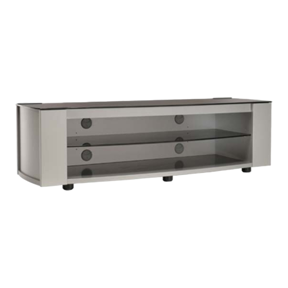
Summary of Contents for Sanus Systems PFV59S
-
Page 2: Part Description
Thin side Left side Long rail Left front Glass shelf Base Glide (gray / black) PART DESCRIPTION: Base Left side Right side Thin side Right front Left front Long rail Back Glass top Glass shelf Steel bracket Angle bracket Cable duct Gray glide Black glide Hardware pack... - Page 3 Bump-on P840022 x 18...
- Page 4 Front edge Glide (gray/black) Back edge Base (underside) Fasten 6 glides to the base as shown. Note that there are 3 gray and 3 black glides. Use gray glides at front of the base if the stand is going to be placed on a light colored floor.
- Page 5 Left side panel Right side panel Small wooden dowels x 12 Press fit small wooden dowels into left and right sides as shown above. Right side panel Left side panel x 12 Insert cams into large holes in left and right sides as shown. Make sure arrows on the cams point towards the corresponding cam holes along the edges of the panels.
- Page 6 Back Screw 4 connector rods into holes indicated in back panel. Base Screw 4 connector rods into holes in the base as indicated above. Insert 2 cams into large holes in the base as shown above.
- Page 7 Left side panel Right side panel Cable duct Press fit the sides to the back as shown above. Turn the cams clockwise to tighten. Press fit 4 cable ducts into large holes in the back as shown. Assistance may be needed for this step. Press fit the sides and back assembly onto the base as shown.
- Page 8 Fasten the back to the base as shown above. Long rail Assistance may be needed for this step. Hold the long rail in between the sides as illustrated. Insert the black barrel nuts into the holes in the long rail. Ensure the holes in the sides are aligned with the holes in the long rail.
- Page 9 Press fit the front panels to the sides and base as shown. Turn the cams clockwise to tighten. Adjusting screw x 4 Thin side Slide thin sides down slots in front panels and back, ensuring silver surfaces face out. Screw each adjusting screw into sides by half of it's visible threaded length, then once this is done, tighten all 4 Adjusting screws fully into sides.
- Page 10 Steel bracket Fit the long steel bracket into the rebate in the long rail and in the grooves in the sides as shown above. Ensure the bracket is equally distanced from the sides on both ends. Once the bracket is adjusted in the sides, fasten it to the long rail using the screws shown above. It is important that you hold the long rail against the steel bracket as you tighten the screws.
- Page 11 Bump-on(self adhesive) x 18 Attach 18 bump-ons to top surface of the back, sides, front rails, and steel bracket where shown above. Assistance may be needed for this step. When placing the glass top on the unit, pay attention to the following tips: * Ensure painted side is facing down.
- Page 12 Fasten the angle brackets to the back as shown above. Note - the angle brackets are essential for the strength of the stand. Assistance will be needed for this step. Insert 2 shelf pins into the bottom holes in the right side. Place a piece of polystyrene (from the pack) onto the base as shown above (Alternatively you could use a soft rag).


Need help?
Do you have a question about the PFV59S and is the answer not in the manual?
Questions and answers