Table of Contents
Advertisement
Quick Links
TABLE OF CONTENTS
WARNING NOTICES
10 METER OPERATION
UNPACKING
1 INSTALLATION
1.1
1.2
1.3
1.4
TRANSCEIVER INTERCONNECTIONS
1.5
1.6
1.7
1.8
1.9
2.1
2.2
2.2.1
2.2.2
2.2.3
2.2.4
2.2.5
2.2.6
2.2.7
2.2.8
2.2.9
2.2.10
2.2.11
TABLE OF CONTENTS
OPR-STBY
2.2.7.a
2.2.7.b
2.2.7.c
Ep
Is
FWD
i-ii
iii-iv
v-vi
vii
vii
viii
ix
1-1
1-1
1-1
1-2
1-2
1-2
1-2
1-3
1-3
2-1
2-1
2-1
2-1
2-1
2-1
2-1
2-1
2-1
2-1
2-1
2-2
2-2
2-2
2-2
2-2
2-2
2-2
i
Advertisement
Table of Contents

Subscribe to Our Youtube Channel
Related Manuals for Ten-Tec TITAN III 417


Summary of Contents for Ten-Tec TITAN III 417
-
Page 1: Table Of Contents
TABLE OF CONTENTS TABLE OF CONTENTS i-ii LIST OF ILLUSTRATIONS iii-iv v-vi SPECIFICATIONS WARNING NOTICES 10 METER OPERATION viii INTRODUCTION UNPACKING 1 INSTALLATION INTRODUCTION ELECTRICAL CONNECTIONS HIGH VOLTAGE TRANSFORMER INSTALLATION TRANSCEIVER INTERCONNECTIONS ANTENNA REQUIREMENTS GROUND CONNECTION HIGH POWER OPERATION COOLING SYSTEM 2 OPERATING INSTRUC TIONS INTRODUCTION FRONT PANEL CONTROLS... - Page 2 REAR PANEL CONNECTIONS AND CONTROLS 2.3.1 TRANSCEIVER 2.3.2 ANTENNA 2.3.3 KEY IN 2.3.4 KEY OUT 2.3.5 PTT/VOX 2.3.6 2.3.7 ALC CONTROL 2.3.8 AC LINE 2.3.9 LINE FUSES INITIAL TURN-ON TUNE – UP PROCEDURE 2.5.1 CHECKS TO MAKE BEFORE TUNING UP 2.5.2 IMPORTANT POINTS TO REMEMBER 2.5.3...
-
Page 3: List Of Illustrations
LIST OF ILLUSTRATIONS DESCRIPTION PAGE T/R CONNECTIONS FOR TEN-TEC TRANSCEIVERS WITH TX OUT AND TX EN T/R CONNECTIONS FOR OTHER TRANSCEIVERS MODEL 417 TUNING CHART MODEL 417 TUNING LOG MODEL 417 FRONT PANEL MODEL 417 REAR PANEL MODEL 417 TOP VIEW... -
Page 4: Circuit Trace Component Layout
ASSEMBLY A12 (81947) METER/SWITCH BOARD 5-13 COMPONENT LAYOUT 5-10 5-14 CIRCUIT TRACE 5-11 ASSEMBLY A13 (81952) DISPLAY BOARD 5-15 COMPONET LAYOUT & TOP CIRCUIT 5-10 5-16 BOTTOM CIRCUIT TRACE 5-12 ASSEMBLY A9 (81945) AC LINE / DELAY BOARD 5-17 COMPONENT LAYOUT 5-12 5-18 CIRCUIT TRACE... -
Page 5: Specifications
SPECIFICATIONS MODEL 417 BAND COVERAGE 160, 80, 40, 30, 20, 17, and 15 meters (12 and 10 meters for authorized users). POWER OUTPUT 1500 watts continuous in SSB, CW, AMTOR/PACTOR (50% duty cycle modes) on all bands. 1000 watts RTTY/SSTV (continuous duty cycle modes) for up to 10 minutes on 160, 80, 40, 20, 15, and 10 meter bands (750 watts on WARC bands 30, 17, and 12 meters). - Page 6 METERING Full time plate current meter. Second meter selectable for screen grid current, plate voltage, forward power, and reflected power (x10). Peak forward power indicated on full-time LED bargraph display. FRONT PANEL CONTROLS TUNE and LOAD control knobs with 6:1 reduction drive. Rotary band switch and meter switch for screen grid current, plate voltage, forward or reverse power.
- Page 7 WARNING!!!!!!! This amplifier contains lethal voltages when operating. DO NOT operate this amplifier with the covers removed. The power supply circuits in this amplifier can produce up to 3000 volts and cause serious injury or death! CAUTION!!! Never attempt to operate the TITAN III without first connecting a suitable antenna or 50 ohm dummy load of sufficient power rating or SERIOUS DAMAGE MAY RESULT!
-
Page 8: Introduction
Band coverage includes 160, 80, 40, 30, 20, 17 and 15 meters as shipped from the factory. With proof of authorization, 12 and 10 meters may be enabled with an optional matching network from TEN-TEC. Primary power of 240 VAC is required. Remember, tune-up at 1500 watts output and 240 VAC line voltage can require up to 20 amps line current. - Page 9 1 ea. operator’s manual 74367 2 ea spare 14” tube chimney clamp 38265 If any of the above are missing, contact the repair department at TEN-TEC for replacement. Repair dept. (865) 428-0364 Switchboard (865) 453-7172 (865) 428-4483 Before powering up your TITAN III, visually inspect the unit for possible physical damage, such as dents or parts jarred loose during shipment.
-
Page 10: Introduction
CHAPTER 1 INSTALLATION 1.1 INTRODUCTION: When setting up of the transformer coil toward the center the station, provide adequate ventilation for chassis shield. Being careful not to disturb the amplifier. Also, select a location that the printed circuit board behind the meters, allows comfortable access to the front align the slots in the transformer bottom controls and adequate clearance for rear... -
Page 11: 1.5 Antenna Requirements
1.4 TRANSCEIVER INTERCONNECTIONS: When using the CAUTION!!! TITAN III with TEN-TEC transceivers with TX EN and TX OUT connectors, follow the Never attempt to operate the TITAN III diagram in Figure 1-1. The QSK-PTT/VOX without first connecting a suitable switch on the TITAN III should be in the antenna or 50 ohm resistive load of QSK position for all modes of operation. -
Page 12: Alc
structures. For the first few hours of depending on input RF drive level. A operation, check the SWR negative output voltage will be present at the frequently. Any increase in ALC jack only when the TITAN III is in the reflected power is an indication that OPERATE mode and the input RF drive is something between the amplifier and... - Page 13 TITAN III TITAN III FIGURE 1-1 T/R CONNECTIONS FOR TEN-TEC TRANCEIVERS WITH TX OUT & TX EN TITAN III TRANSCEIVER TITAN III FIGURE 1-2 T/R CONNECTIONS FOR OTHER TRANCEIVERS WITHOUT TX OUT & TX EN...
-
Page 14: Operating Instructions
CHAPTER 2 OPERATING INSTRUCTIONS 2.1 INTRODUCTION: The following 2.2.5 OPERATE/STANDBY: This switch, instructions will enable the operator to quickly when in the OPERATE position, places the place the TITAN III in operation. Included are amplifier online. When in the STANDBY descriptions of the front panel controls and rear position, the amplifier is bypassed and only panel connections, followed by a detailed tune-... -
Page 15: Ref
VAC the meter will read a little higher LED goes out and the TITAN III can be (3125 VDC). placed in the operate mode. B. Screen current (Is) - When in this position, the meter is paralleled with a resistor in 2.2.11 PEAK POWER BARGRAPH: series with the screen supply. -
Page 16: Alc
When used with late model TEN-TEC 2.5 TUNE UP PROCEDURE: The transceivers, this jack is not used. When used following section describes important points with other transceivers, this jack is connected to to observe during tune up. A suggested... -
Page 17: Suggested Tune - Up Procedure
power output. Adjust the LOAD 2.5.3 SUGGESTED TUNE UP PROCEDURE: Following is the control for minimum screen grid recommended procedure for safe and proper current consistant with desired power tune up of the TITAN III. output. You will find that these values A. -
Page 18: Model 417 Tuning Chart
FREQUENCY BAND LOAD TUNE 160A 1.820 160B 1.980 3.500 80 / 75 3.980 7.040 10.120 14.050 14.250 18.110 21.050 24.900 28.100 FIGURE 2-1 MODEL 417 TUNING CHART FOR AN IDEAL 50 OHM LOAD... -
Page 19: Model 417 Tuning Log
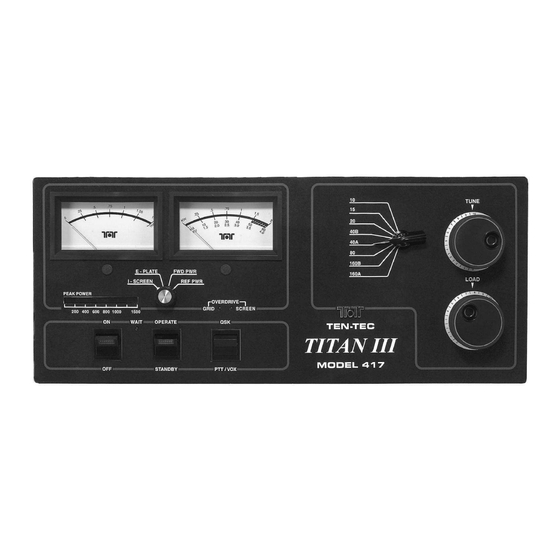
BAND FREQUENCY LOAD TUNE ANTENNA NOTES FIGURE 2-2 MODEL 417 TUNING LOG... - Page 20 FIGURE 2-3 TITAN III FRONT VIEW FIGURE 2-4 TITAN III REAR VIEW...
- Page 21 FIGURE 2-5 TITAN III TOP VIEW...
- Page 22 FIGURE 2-6 TITAN III BOTTOM VIEW...
-
Page 23: Operation And Safety
CHAPTER 3 OPERATION AND SAFETY 3.1 INTRODUCTION: The following paragraphs provide additional information for operation of and safety from your TITAN III amplifier. 3.1.1 HIGH POWER TETRODES: The 4CX800As are very rugged and normally operate with a large margin of safety in the TITAN III. They will deliver outstanding service for many years if not damaged by abuse...especially excessive grid current or blockage of cooling air flow. -
Page 24: Maintenance
CHAPTER 4 MAINTENANCE AND TROUBLESHOOTING 4.2 MAINTENANCE: The amplifier 4.1 INTRODUCTION: If you encounter a compartment, particularly areas around high problem, the troubleshooting hints listed in voltage components should be cleaned often TABLE 4-1 below will help isolate the (using a soft bristled brush and vacuum nature of the problem. - Page 25 TABLE 4-1 TROUBLESHOOTING HINTS (Continued) 5. Relays A9K1, A9K2, and A9K3 close at turn A] High voltage shorted at crowbar or on, but line fuses blow. elsewhere. B] Shorted tube. C] Leaky electrolytics in high voltage supply. 6. Amplifier won’t drive, zero grid and plate A] Defective cable from transceiver to current, high input SWR .
-
Page 26: Circuit Descriptions And Illustrations
FILTER BOARD A8 (81954) is available negative voltage proportional to input from TEN-TEC to qualified amateur radio operators, upon receipt of a copy of their power for control of some exciters. The amateur radio license. - Page 27 FIGURE 5-1 INPUT MATCHING BOARD (ASSEMBLY A6) CIRCUIT TRACE AS VIEWED THROUGH BOARD FIGURE 5-2 INPUT MATCHING BOARD (ASSEMBLY A6) COMPONENT LAYOUT TOP VIEW...
-
Page 28: Circuit Trace
H.V. POWER SUPPLY BOARD A2 (81944) This board contains the high voltage rectifier bridge (D1 – D20), H.V. filters (C1 – C8 and C14), and H.V. meter circuits. FIGURE 5-3 HIGH VOLTAGE RECTIFIER BOARD (ASSEMBLY A2) CIRCUIT TRACE AS VIEWED THROUGH BOARD FIGURE 5-4 HIGH VOLTAGE RECTIFIER BOARD (ASSEMBLY A2) COMPONENT LAYOUT TOP VIEW... - Page 29 5.4 SCREEN SUPPLY AND GRID BIAS BOARD A10 (81950) This board contains the screen supply, grid bias supply, and protective circuits for the 4CX800As. The screen voltage is rectified by diodes D4 – D7 and filtered by C1 – C3 and C15. This DC voltage is then regulated by pass element Q8.
- Page 30 TOP SIDE COPPER BOTTOM SIDE COPPER FIGURE 5-6 SCREEN SUPPLY (ASSEMBLY A10) CIRCUIT LAYOUT VIEWED THROUGH BOARD FROM TOP...
- Page 31 5.5 QSK BOARD A11 (81949) This board contains the low voltage supply, turn-on relay sequencing circuits, and T/R relay control. The low voltage is rectified by D1 – D4 and filtered by C6. U1 and Q2 provide regulation for all low voltage circuits except the negative 16 VDC supply. After a 3 minute warm-up period determined by RC time constant of R4 and C5,Q19 and Q11 will conduct, turning on the pass element Q7.
-
Page 32: Circuit Trace
FIGURE 5-8 QSK BOARD (ASSEMBLY A11) TOP AND BOTTOM CIRCUIT TRACES VIEWED THROUGH BOARD FROM TOP... - Page 33 5.6 SWR BOARD A4 (81951) This board contains the input relay K1, output relay A14, hot- shot speed-up circuit Q3-C19, and the SWR bridge T1 for output power sampling. FIGURE 5-9 SWR BOARD (ASSEMBLY A4) CIRCUIT TRACE VIEWED THROUGH BOARD FROM TOP TOP COPPER BOTTOM COPPER FIGURE 5-10 SWR BOARD (ASSEMBLY A4)
- Page 34 5.7 PLATE BOARD A3 (81948) This board contains the parasitic suppressors and coupling capacitors to connect the 4CX800A plates to the amplifier tank circuit. FIGURE 5-11 PLATE CONNECTOR BOARD (ASSEMBLY A3) CIRCUIT TRACE VIEWED THROUGH BOARD FIGURE 5-12 PLATE CONNECTOR BOARD (ASSEMBLY A3) COMPONENT LAYOUT TOP VIEW...
-
Page 35: A13 (81947 And 81952)
5.8 METER/SWITCH BOARD A12 (81947) and DISPLAY BOARD A13 (81952) This board contains the metering circuits for the front panel meters. A12S1 selects the parameter to be monitored. This selection is then sent to multimeter M1. The multimeter has three calibrated scales for measuring plate voltage, screen current and forward or reflected RF power. - Page 36 COMPONENT SIDE COPPER SOLDER SIDE COPPER FIGURE 5-14 METER/SWITCH BOARD (ASSEMBLY A12) CIRCUIT VIEWED THROUGH BOARD FROM FRONT PANEL 5-11...
- Page 37 FIGURE 5-16 DISPLAY BOARD (ASSEMBLY A13) BOTTOM CIRCUIT VIEWED THROUGH BOARD FROM TOP U1 GRN U2 GRN U3 GRN U4 GRN U5 GRN U6 GRN U7 RED AC LINE DELAY BOARD A9 (81945) This board contains the step start relays and associated circuitry to control inrush current while the H.V.
- Page 38 TOP COPPER BOTTOM COPPER FIGURE 5-18 AC LINE DELAY BOARD (ASSEMBLY A9) CIRCUIT TRACE TOP VIEW THROUGH BOARD 5-13...
-
Page 39: Component Layout
5.10 LOAD SHUNT BOARD A5 (81943) This board contains some of the extra load capacitance needed for the tank circuit on the 160M band. Capacitance is paralleled across the variable load capacitor on bandswitch positions 160A, and 160B, and 80. FIGURE 5-19 LOAD SHUNT CAP BOARD (ASSEMBLY A5) CIRCUIT VIEWED THROUGH BOARD FROM TOP BOTTOM COPPER... - Page 40 FIGURE 5-21 SCHEMATIC DIAGRAM MODEL 417 5-15...
-
Page 41: Master Parts List
CHAPTER 6 MASTER PARTS LIST MODEL 417 CHASSIS MOUNTED PARTS A1 ITEM DESCRIPTION TEN-TEC PART # HV TRANSFORMER 81859 FROM 21199 LV TRANSFORMER 21198 BLOWER CENT. BLOWER 38305 SHORTING BAR 93690 INTERLOCK SW 32063 ON-OFF SW 32128 STBY-OPR SW 32129 QSK –PTT SW... - Page 42 AC LINE BOARD A9 81945 ITEM DESCRIPTION TEN-TEC PART # .01uF 1KV 23013 .01uF 1KV 23013 1uF 50V 23264 .01uF 1KV 23013 RELAY SPST 32067 RELAY SPST 32067 RELAY SPST 32067 COVER, RELAY 32072 MPSA14 25253 30155 100K 30161 30154...
- Page 43 METER-SWITCH BOARD A12 81947 ITEM DESCRIPTION TEN-TEC PART # .01uF 23260 .01uF 23260 .01uF 23260 .01uF 23260 .01uF 23260 .1uF 23261 .01uF 23260 1uF 50V 23264 .01uF 23260 .01uF 23260 .1uF 23261 .1uF 23261 .01uF 23260 .01uF 23260 .01uF 23260 .01uF...
- Page 44 ITEM DESCRIPTION TEN-TEC PART # 4.7K 30146 2.2K 30142 30132 1.5K 30140 100K 30161 100K 30161 100K 30161 10K TRIMPOT 30038 100K PC ADJ 30620 100K PC ADJ 30620 10K TRIMPOT 30038 100K TRIMPOT 30198 METER SW 98449 FROM 32050...
- Page 45 ITEM DESCRIPTION TEN-TEC PART # 10uF 23266 10uF 23266 .01uF 23260 .01uF 23260 .01uF 23260 .01uF 23260 .01uF 23260 .01uF 23260 .01uF 23260 .01uF 23260 .01uF 23260 .01uF 23260 .56uF 23331 1uF 50V 23263 .01uF 23260 .01uF 23260 .1uF 23261...
- Page 46 ITEM DESCRIPTION TEN-TEC PART # MPSW01 25053 2N4124 25258 2N4124 25258 2N4124 25258 2N4124 25258 2N4124 25258 2N6027 UJT 25185 2N5087 25001 2N4124 25258 2N5087 25001 2N4124 25258 30138 30138 30150 3.9M 30180 30138 30138 1.5K 30140 30138 30138 30138...
- Page 47 ITEM DESCRIPTION TEN-TEC PART # 30150 30150 30150 30150 10K TRIMPOT 30619 30150 30150 2.2K 30142 4.7K 30146 30150 30150 30150 4.7K 30146 10K ALC POT 30267 LM7812 25232 SCREEN SUPPLY BOARD A10 81950 100uF 160V 23516 100uF 160V 23516...
- Page 48 ITEM DESCRIPTION TEN-TEC PART # 1A 1KV 28122 1N5368 47V ZENER 28136 1N5363 30V ZENER 28134 1N5363 30V ZENER 28134 1N5383 150V ZENER 28135 1N5383 150V ZENER 28135 1N4007 28043 1N751 5.1V ZENER 28041 1N4148 28001 1N964 13V ZENER 28010...
- Page 49 SWR BOARD A4 81951 ITEM DESCRIPTION TEN-TEC PART # 3-22pF 23169 .01uF 23260 .01uF 23260 1uF 50V 23264 1uF 50V 23264 330pF 23397 10pF 23371 10pF 23371 18pF 23373 18pF 23373 .01uF 23260 .01uF 23260 .01uF 23260 .01uF 23260 .01uF 23260 .01uF...
- Page 50 ITEM DESCRIPTION TEN-TEC PART # 2.2uH 21116 15uH 21126 1mH RFC 21135 2N6517 25393 2N4124 25258 MPSA14 25253 47 OHM 2W 30408 330K 30302 30136 330K 30302 30150 330K 30302 4.7K 30146 100K 30161 100K 30161 100K 30161 30150 100K...
Need help?
Do you have a question about the TITAN III 417 and is the answer not in the manual?
Questions and answers