
Subscribe to Our Youtube Channel
Related Manuals for Eurotherm Drives 635

Summary of Contents for Eurotherm Drives 635
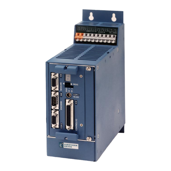
- Page 1 EUROTHERM DRIVES DIGITAL SERVO DRIVE B-07-01-05-06-001.jpg PRODUCT MANUAL Product-manual Model: 635/DER u. 635/K DER 07-01-05-06-E-V1002.doc...
-
Page 2: Ul: 07-01
UL: 07-05-03-02 Product - manual Businterface CAN for 635 637 637+ UL: 07-05-04-02 Product - manual Businterface DP for 635 637 637+ UL: 07-05-05-02 Product - manual Businterface Interbus S for 635 637 637+ Product-manual Model: 635/DER u. 635/K DER 07-01-05-06-E-V1002.doc... -
Page 3: Ul: 07-05
Further descriptions, that relate to this document. UL: 07-05-07-02 Product - manual IO Interface for 635 637 637+ UL: 07-09-04-02 Product - manual Supression aids EH UL: 10-06-03 Product - manual Serial transfer protocol 635 637 637+ EASY-seriell UL: 10-06-05... -
Page 4: Table Of Contents
635/K DER 01...10 ...............22 Connector pin assignments and contact functions............23 2.2.1 Power connections for plug-in module 635/DER standard ..........23 2.2.2 for plug-in module 635/DER ...-N (with integrated power supply) special .....24 2.2.3 Signal connections......................25 2.2.3 Resolver..........................28 2.2.4 Multifunktion X40......................29... - Page 5 Measuring sockets MP1 and MP2 ..................66 11.9 Thermal data ........................66 11.10 Mechanical data........................66 Disposal..........................67 Software...........................68 EASYRIDER < .......................68 13.1 13.2 BIAS- commands ......................69 13.3 BIAS- extended command overview................71 Certificates ........................72 Index ..........................76 Notes..........................77 Modification Record.......................78 Product-manual Model: 635/DER u. 635/K DER 07-01-05-06-E-V1002.doc...
-
Page 6: The Most Important Thing First
Depending on the kind of application, additional norms e.g. UL, DIN are to be observed. If our products are employed in connection with components from other manufacturers, their operating instructions are also to be strictly observed. Product-manual Model: 635/DER u. 635/K DER 07-01-05-06-E-V1002.doc... -
Page 7: Saferecaty Putions
Danger to your life ! Caution ! Opening the servo drive by the operator is prohibited due to reasons of safety and guarantee. The requirement for problem-free operation of the servo drive is the expert configuring ! Product-manual Model: 635/DER u. 635/K DER 07-01-05-06-E-V1002.doc... - Page 8 Before putting into operation, remove additional covers so that the unit does not overheat. With measurements at the servo drive it is absolutely necessary to observe the potential separation! Stop ! Eurotherm Drives Limited is not liable for damages whith occur by not following the instructions or the applicable regulations !! Product-manual...
-
Page 9: General
The AC-supply voltage is fed directly or via transformer to the associated power supply module. The devices are designed to be operated on networks which are grounded on centre point (TN networks) ! Product-manual Model: 635/DER u. 635/K DER 07-01-05-06-E-V1002.doc... - Page 10 (TN networks) ! c) Special design – variants For example operation: Ø DC motors with resolver Ø DC motors with incremental encoder Ø DC motors with tacho Information: only on request! Product-manual Model: 635/DER u. 635/K DER 07-01-05-06-E-V1002.doc...
-
Page 11: Digital Communication
The possibilities range from simple current and speed control to programmable position control processes (PLC) supported by the 1500 BIAS- command blocks. refer to: Chapter 3 Operating modes Chapter 13.2 BIAS commands Chapter 13.3 Extended BIAS-commands Product-manual Model: 635/DER u. 635/K DER 07-01-05-06-E-V1002.doc... -
Page 12: Compatibility To Eurotherm- 3 U Analog Regulator Esr Ac S
1.1.4 Compatibility to series APOLLO 2G Output power supply +5V DC / 150mA for encoder via decoupling diode at X40.9. Incremental signal with pulse interval. Compatibility restrictions: Furthermore, there are no compatibility restrictions. Product-manual Model: 635/DER u. 635/K DER 07-01-05-06-E-V1002.doc... -
Page 13: Key To The Models
Model: XXX/ -XXX Marking Description XXX/ = 635 ≅ Eurotherm-design (blue) = Compact 1 axis servo drive system = (is not used with model plug-in device) = Low-cost compact design, only for 2,5A rated current ! DER = Digital Europe Regulator... -
Page 14: Range Data
DIN IEC 68-2-6, test FC Condition for testing Frequency range 10...57Hz 57...150Hz Amplitude 0,075 mm Acceleration Test time per axis 10 Frequenzzyklen Frequency sweep speed 1 Oktave/min 1) Use only fan-cooled devices. For reduced operating conditions, no UL-Approbation are available. Product-manual Model: 635/DER u. 635/K DER 07-01-05-06-E-V1002.doc... -
Page 15: Compact Units 635/K Der
L 230 / 18TE * 25 Power-losses Fan, Electronic Powerstage per A [W/A] Weight [kg] 2,75 2,90 3,45 Further data see: chapter 11 General technical data suggested: transformer-based supply use only Eurotherm-released types Product-manual Model: 635/DER u. 635/K DER 07-01-05-06-E-V1002.doc... -
Page 16: Plug-In Modules 635/Der
Cont. Power Min. external Resistor [Ω] General Power-losses Fan, Electronic Powerstage per [W/A] Weight [kg] 0,75 0,90 1,20 Further data see: chapter 11 General technical data suggested: transformer-based supply use only Eurotherm-released types Product-manual Model: 635/DER u. 635/K DER 07-01-05-06-E-V1002.doc... -
Page 17: Single- And Three-Phase Supply
Ukl = 1,2 * (EMF * n / 1000) + I * (Rph + RL) [V] Ukl required motorvoltage [V RMS] EMF Back-EMF of motor [V RMS] / 1000 RPM Rph resistance of motor (between terminals) [Ω] line resistance of motor cable [Ω] motor-current [A RMS] Product-manual Model: 635/DER u. 635/K DER 07-01-05-06-E-V1002.doc... -
Page 18: Output Power
Output-Voltage [%] 1.3.7 Rated current / max. current – period Guaranteed minimum requirements value I2T- work load Series 631/5/7 120.00 Imax/Inenn=2 Imax/Inenn=1,75 Imax/Inenn=1,5 Imax/Inenn=1,25 100.00 Imax/Inenn=1 80.00 60.00 40.00 20.00 0.00 time [sec] Product-manual Model: 635/DER u. 635/K DER 07-01-05-06-E-V1002.doc... -
Page 19: Dimensions And Layout
2 x 3mm = 6mm Important: Make sure you leave an additional space of approx. 70 mm on the front side for the signal mating plugs ! Product-manual Model: 635/DER u. 635/K DER 07-01-05-06-E-V1002.doc... -
Page 20: Emc Bow (Optional)
Dimensions and layout 1.4.2 EMC bow (optional) side view front view EMC bow for Resolver cable Mains cable Motor cable meaning: 1,2,3 = cage clamp terminal Product-manual Model: 635/DER u. 635/K DER 07-01-05-06-E-V1002.doc... -
Page 21: Layout
The configuration modules can only be reached after removing the plugs. 1.4.3.2 Layout of power board Solder side H15- power plug JP201 JP100 JP102 JP200 JP101 Sold er jump er JP100, JP101, JP102 und JP 200,201 (Function see Chap ter 7.1 Jump er) Product-manual Model: 635/DER u. 635/K DER 07-01-05-06-E-V1002.doc... -
Page 22: General View Of Connections
General view of connections of the compact device 635/K DER 01...10 Power connection: 1 * 230V AC 635/ K DER01...07 3 * 230V AC ...01...10 LNF B L3 ' M6 for ground connection L2 ' L1 ' grounding bar switching cabinet... -
Page 23: Connector Pin Assignments And Contact Functions
Connector pin assignments and contact functions 2.2.1 Power connections for plug-in module 635/DER standard at the rear of the rack (H15-multiple pin strip according to DIN 41612) DC bus in the rack to further regulators H15 strip R Ballast grounding bar... -
Page 24: For Plug-In Module 635/Der
Connector pin assignments and contact functions 2.2.1.1 for plug-in module 635/DER ...-N (with integrated power supply) special at the rear of the rack (H15-multiple pin strip according to DIN 41612) external DC-BUS-capicator for max. currents >2,5A at least 60 µF/A, voltage endurance ³... -
Page 25: Signal Connections
Analog- 0..+-10V JP101 monitor MP2 can be normed 0..+-10V can be normed Nsetpoint +12V referene potential 0..+-10V Analog-monitor MP1 can be normed 0V PLC +12V 80mA -12V 80mA 0V PLC shield Product-manual Model: 635/DER u. 635/K DER 07-01-05-06-E-V1002.doc... - Page 26 1) Security- and supervising logic, to be programmed by user ! 2) IMPORTANT: The Power-Supply for the Motor-Brake has to be adapted to the type of Brake. Voltage-Drops caused by long cables also may effect malfunctions of the Brake Product-manual Model: 635/DER u. 635/K DER 07-01-05-06-E-V1002.doc...
- Page 27 OPTO input L = output stage inactive fixed: active configurable (chapter 3) Relais output configurable (chapter 3) OPTO input configurable (chapter 3) OPTO input Data of the digital inputs and outputs see chapter 11 Product-manual Model: 635/DER u. 635/K DER 07-01-05-06-E-V1002.doc...
-
Page 28: Resolver
Bear. 09.05.01 Blue resolver cable 10.05.01 Gep. for Eurotherm standard motors and servo drives Norm Zeichnungsnummer / drawing No Blatt sheet Z-RK.6300.xxxx Zust. Änderung Datum Name Ursprung Dateiname / File name: Z-RK.6300.xxxx_E.cdr Product-manual Model: 635/DER u. 635/K DER 07-01-05-06-E-V1002.doc... -
Page 29: Multifunktion X40
0,0 ... 5,0V nominal signal difference: 1,0V current consumption: 1...4 mA (depending on frequency) Notice: Master / Slave operation 1 Master maximum 8 Slaves Condition: Devices directly side by side ! Product-manual Model: 635/DER u. 635/K DER 07-01-05-06-E-V1002.doc... - Page 30 X40. n = max. speed (rpm) x = increments e.g. 1024 f = output frequency at X40.1,2,4,5 Formula: [Hz] Example: n = 4000 rpm (4000 1024) 81920 Incremental Outputs Product-manual Model: 635/DER u. 635/K DER 07-01-05-06-E-V1002.doc...
- Page 31 Supply voltage output max. 150 mA +5 VDC Note: The operation of incremental encoders via long cables may cause a voltage drop of the encoder power supply. We suggest the use of external supply if necessary. Incremental Inputs Product-manual Model: 635/DER u. 635/K DER 07-01-05-06-E-V1002.doc...
- Page 32 Shield connector Shield Pulse direction (-) inverted Pulse direction (-) Reference potential Pulse direction (+) inverted Pulse direction (+) Supply voltage output max. 150 mA +5 VDC pulse direction (+) pulse direction (-) Product-manual Model: 635/DER u. 635/K DER 07-01-05-06-E-V1002.doc...
-
Page 33: Digital Interfaces
Received data view: solder side Metal enclosure Shield Notice: The service interface RS232 is not galvanically separated and should not be planned for this reason as a operating interface ("firm wiring")! Product-manual Model: 635/DER u. 635/K DER 07-01-05-06-E-V1002.doc... - Page 34 The connections COM2 and X30 are implemented via SUB D09 socket. The costumer have to be guaranteed that an interchanging is not possible! 2.2.5.3 Interface – design design C design A design B coding Product-manual Model: 635/DER u. 635/K DER 07-01-05-06-E-V1002.doc...
- Page 35 RP 422 without galvanic seperation with configuration board RP 485 with galvanic seperation assignment as RS422/485 design A Data In Data In invertiert Data Out invertiert Data Out Daisy-chain wiring up to 16 devices Product-manual Model: 635/DER u. 635/K DER 07-01-05-06-E-V1002.doc...
- Page 36 Potential +5V Line A 2.2.5.8 Pin assignment for SUCOnet K with configuration board RP SUC, with galvanic seperation Description Designation design B Data line + TA/RA Signal ground SGND Data line - TB/RB Product-manual Model: 635/DER u. 635/K DER 07-01-05-06-E-V1002.doc...
- Page 37 Datenleitung IN Hinweg design B (Differenzspanung A) Datenleitung OUT Rückweg (Differenzspanng A) Bezugspotential GND I Datenleitung IN Hinweg /DO1 (Differenzspanung B) Datenleitung OUT Rückweg /DI1 (Differenzspanung B) Attention: specific front panel is required ! Product-manual Model: 635/DER u. 635/K DER 07-01-05-06-E-V1002.doc...
- Page 38 The input´s with the internal number 107 and 108 must be connected to the pin´s with number 3 and 4. The output´s with the internal number 109 and 110 must be connected to the pin´s with number 7 and 8. Product-manual Model: 635/DER u. 635/K DER 07-01-05-06-E-V1002.doc...
-
Page 39: Operating Modes
BIAS acc. to programming (up to 1500 command blocks) or via digital PLC - functions communication for further informations: EASYRIDER < (e.g. fieldbus) see chapter 13.1 BIAS-commands and 13.2 Product-manual Model: 635/DER u. 635/K DER 07-01-05-06-E-V1002.doc... -
Page 40: Operating Modes And Pin Functions
F0, F1, F3 F0, F1, F2, F3 X10.20 Output F0, F2 F0, F1 F0, F1, F3 F0, F1, F2, F3 X10.23 The assignment of the functions F0..F3 is listed in the following table Product-manual Model: 635/DER u. 635/K DER 07-01-05-06-E-V1002.doc... -
Page 41: Configurable Pin-Functions (Depending On The Operating Mode)
*) With every row (from the top to the bottom) in which the function F2 is assigned to an input, the binary value (2 n ) increases by 1. (see example) Operating mode 4: only permissible set number 0 - 9 ! y fast input for optimal timing Product-manual Model: 635/DER u. 635/K DER 07-01-05-06-E-V1002.doc... -
Page 42: Function Diagrams From Inputs And Outputs
A ctive tv ; reactio n time fo r b ra ke o u tpu t A KTIVE -O K(F0 ) X1 0 .2 3 (ho ld ing b rake ) Product-manual Model: 635/DER u. 635/K DER 07-01-05-06-E-V1002.doc... -
Page 43: Mechanical Installation
If the device becomes operated in a not ventilated device, the case volume of the specified control cabinet must be calculated in accordance with the following table ! Device Volume/control cabinet 635/K DER01...DER10 0,12 m³ For more exact information, please, address to the control-cabinet manufacture Product-manual Model: 635/DER u. 635/K DER 07-01-05-06-E-V1002.doc... -
Page 44: Electrical Installation
Due to the working-principle of servo drives there may discharge currents to PE exceeding DC 10mA resp. AC 3,5mA. Suitable for use on a circuit capable of delivery not more than 5000 RMS symmetrical amperes 505V maximum. (Note according to UL508C) Product-manual Model: 635/DER u. 635/K DER 07-01-05-06-E-V1002.doc... -
Page 45: Fuses, Contactors, Filters
Rule of the Thumb: 1,5 to 2 times of added rated currents Power-On-Peaks Depending on Power-Supply-Unit, Limiting equipment is requiered (Delay-Contactor) only for use in earth referenced supplies(TN). Current-Drain to PE ! Filter types Orientation: Table of Compact-Units. Further Types: see separate manual Product-manual Model: 635/DER u. 635/K DER 07-01-05-06-E-V1002.doc... -
Page 46: Brake Resistor
[kgm²] speed at Brake-Start [RPM] tb1 braking time [Sec] cykle time [Sec] brake-current [A] Rph resistance of motor (between terminals) RL line resistance of motor cable [ 8 ] Product-manual Model: 635/DER u. 635/K DER 07-01-05-06-E-V1002.doc... -
Page 47: Configuration Of The Brake Resistor
Possible ballast circuit configurations at digital devices a) Compact design The plug-in modules of servo-control series 635 / 637 are provided with an on board ballast electronics. It is intended for application as compact unit KDER resp. KD6R. These compact units contain the necessary ballast resistor incl. fuse for the ballast circuit. -
Page 48: Additional Informations
Pmax / Pd <= 59 Caution ! Placing of external brake resistors Brake-resistor are dissipating heat ! Make sure, that there will be no fire-danger in case of operating the resistor in nominal- or fail-conditions Product-manual Model: 635/DER u. 635/K DER 07-01-05-06-E-V1002.doc... -
Page 49: Wiring Instructions
That means, all ground-connecting parts have to use area. The measurements made are valid under the use of Eurotherm - cables, suppression aids and line filters and by application of the following wiring instructions: Product-manual Model: 635/DER u. 635/K DER 07-01-05-06-E-V1002.doc... -
Page 50: Hints For Mounting
Take care for good general grounding of the complete system. Interconnect several mounting-plates with copper-rails or copperband. Take care for ground connection between conrol-cubicle and machine ! Product-manual Model: 635/DER u. 635/K DER 07-01-05-06-E-V1002.doc... -
Page 51: Example For Mounting
Flat cable in case of and separate them from power-lines short distance, otherwise: shielded cable Input COM2 Eurotherm resolver cable model KIR Line feed-in Conductive area to screen Cable channel for control lines Control cubibcle grounding bar Product-manual Model: 635/DER u. 635/K DER 07-01-05-06-E-V1002.doc... -
Page 52: Achieveable Specifications And Conditions
≥ 15 dB cores attenuation Residential EN50081-1/ LNF S/E chapter EN55011 Klasse B chapter 5.6 LNF B Interference Industrial EN50082-2 immunity: (≅ radiation) transmitted by cable or by air Residential Product-manual Model: 635/DER u. 635/K DER 07-01-05-06-E-V1002.doc... -
Page 53: Setting And Programming
The whole range is divided in 32 steps and will be displayed as follows: smallest value largest value , ..If an error occurs, the programming operation is switched off. Product-manual Model: 635/DER u. 635/K DER 07-01-05-06-E-V1002.doc... -
Page 54: Bedienung Des Prog-Tasters
Nr./no.32 hold for 4sec. Store in EPROM? flashes norm. operation 1) hold for 4sec. yes hold for 4sec. => normal operation 1) 1) normal operation: Ucc and Us on, no failure Product-manual Model: 635/DER u. 635/K DER 07-01-05-06-E-V1002.doc... -
Page 55: Commissioning
The system must be in accordance with all valid safety specifications. The function of all safety equipment (limit-switches for example) have to be checked. To activate the power-stage of the drive, the "ACTIVE"-signal (X10.22 against X10.9) has to be exited. Product-manual Model: 635/DER u. 635/K DER 07-01-05-06-E-V1002.doc... -
Page 56: Commissioning In Steps
Tuning-parameters for current loop will be calcualated parameters and offered to the user. Normally, these values give dynamic servo motion. store data power-fail-save in the drive (F7) Menue: Tuning speed loop Product-manual Model: 635/DER u. 635/K DER 07-01-05-06-E-V1002.doc... - Page 57 Select the menu File "store parameters" and store the data save data in the regulator, protected against loss, with the F7-key. Product-manual Model: 635/DER u. 635/K DER 07-01-05-06-E-V1002.doc...
- Page 58 Rated values can be sourced either digital by the internal generator or analog by using +/-10V at X10.5/18. ATTENTION ! Tuning of current loop should be only done after consultation of Eurotherm experts. continue with 9 Product-manual Model: 635/DER u. 635/K DER 07-01-05-06-E-V1002.doc...
-
Page 59: Diagnosis And Trouble Shooting
I²t does the control loop oscillate? P-amplification too high mechanics stiff? requirements too high? is warning /8/ evaluated? Reaction to these errors see chapter 3.3 With configuration corresponding chapter 3.1 Product-manual Model: 635/DER u. 635/K DER 07-01-05-06-E-V1002.doc... - Page 60 With configuration corresponding chapter 3.1 * Only warning respect. status indicator The error signals are shown as long as there is control voltage (Us), also when the power (DC-Bus) is switched off for safety reasons. Product-manual Model: 635/DER u. 635/K DER 07-01-05-06-E-V1002.doc...
-
Page 61: Reset Of A Regulator Trouble
After remove of the tracking error deactivation “ “, the warning message “L“ (tracking error) is active up to the next move command. The error signal “ ≡ ≡ ≡ ≡ “(releasing before ready) can be reset by deactivation the drive Product-manual Model: 635/DER u. 635/K DER 07-01-05-06-E-V1002.doc... -
Page 62: Trouble Shooting
Resolver incorrectly adjusted? Motor reaches in idling cycle very different Resolver incorrectly adjusted speed when running to the right or to the left 1) Display /3./ or /4./ mostly short after activating; before warning /8./ Product-manual Model: 635/DER u. 635/K DER 07-01-05-06-E-V1002.doc... -
Page 63: Block Circuit Diagram
Block circuit diagram Product-manual Model: 635/DER u. 635/K DER 07-01-05-06-E-V1002.doc... -
Page 64: General Technical Data
> 2 ms X10.2, X10.4, X10.11, X10.14, X10.15, X10.24 reaction time of the intputs 0,2 ms X10.4, X10.25 (configured as latch input "see chapter 3") Effect of cycle-time ≤ 0,02 ms Product-manual Model: 635/DER u. 635/K DER 07-01-05-06-E-V1002.doc... -
Page 65: Digital Control
16384 Incr. 14 bit absolute position accuracy +/- 0,52 ° relative position accuracy +/- 0.08 ° Product-manual Model: 635/DER u. 635/K DER 07-01-05-06-E-V1002.doc... -
Page 66: Controllersystem
7 bit, independend of norming internal resistance 10 k 11.9 Thermal data Thermal data see chapter 1.3 11.10 Mechanical data dimensions see chapter 1.4 weight see chapter 1.3 Further data you will find in chapter 1.3.3 Product-manual Model: 635/DER u. 635/K DER 07-01-05-06-E-V1002.doc... -
Page 67: Disposal
The following table shows, which materials can be recycled and which have to be disposed of in a special way. material recycle disposal metal plastics material printed board assembly Dispose of the appropriate materials in accordance with the valid environmental control laws. Product-manual Model: 635/DER u. 635/K DER 07-01-05-06-E-V1002.doc... -
Page 68: Software
Edited data in EASYRIDER are transmitted to the RAM of the servodrive and active after use of the instruction SEND . Only the instruction SAVE in EEPROM writes data into a nonvolatile memory. Data are stored there power-fail save. Product-manual Model: 635/DER u. 635/K DER 07-01-05-06-E-V1002.doc... -
Page 69: Bias- Commands
The BIAS operation set is listed on the next page. You can read the exact function of the individual commands in the help function of the EASYRIDER software in the BIAS editor or in the BIAS command description (UL:10.6.5). Product-manual Model: 635/DER u. 635/K DER 07-01-05-06-E-V1002.doc... -
Page 71: Bias- Extended Command Overview
[D_Variable X] = COS [D_Variable Y] [D_Variable X] = SQRT [D_Variable Y] only defined Mathematics- defined in BIAS and PLC- Tabelle mathematics- program program [Variable X] = program from EASYRIDER and Firmware Version V5.10 ! Product-manual Model: 635/DER u. 635/K DER 07-01-05-06-E-V1002.doc... -
Page 72: Certificates
Certificates Product-manual Model: 635/DER u. 635/K DER 07-01-05-06-E-V1002.doc... - Page 73 Certificates Product-manual Model: 635/DER u. 635/K DER 07-01-05-06-E-V1002.doc...
- Page 74 Certificates Product-manual Model: 635/DER u. 635/K DER 07-01-05-06-E-V1002.doc...
- Page 75 Certificates Product-manual Model: 635/DER u. 635/K DER 07-01-05-06-E-V1002.doc...
-
Page 76: Index
System description ............9, 10 Hints for mounting...............50 System variants..............9 Installation of the rack ............49 The danger of electric shocks ..........44 Insulation concept..............14 Thermal data................ 66 Trouble shooting ..............62 Jumper .................53 Wiring instructions.............. 49 Product-manual Model: 635/DER u. 635/K DER 07-01-05-06-E-V1002.doc... -
Page 77: Notes
Notes Product-manual Model: 635/DER u. 635/K DER 07-01-05-06-E-V1002.doc... -
Page 78: Modification Record
2.2.3.2 text addition BIAS commands 13.2 updated new chapter 11.05.1999 K. Stadler V09.21STPL99 RESET function addition BIAS commands 13.2 updated 17.06.1999 SA/ST V1001 complete modification Eurotherm-Format seperation German / English 11.01.2002 N.Dreilich Product-manual Model: 635/DER u. 635/K DER 07-01-05-06-E-V1002.doc... - Page 79 Ontario L8E 3X7 DENMARK Enghavevej 9D Tel.: +45 (70) 201311 leif.tangaa@eurotherm.se DK-7100 Fax: +45 (70) 201312 Eurotherm Drives Danmark Vejle 15 Avenue de Norvège Tel.: +33 1 (69) 185151 FRANCE Villebon / Yvette Fax: +33 1 (69) 185159 Eurotherm Vitesse Variable...
Need help?
Do you have a question about the 635 and is the answer not in the manual?
Questions and answers