Table of Contents
Advertisement
Quick Links
Flat Head
Pan Head
VESA screw
Socket cap
Package contents
M5x10
#10-24x1/2''
Socket cap
VESA screw
Pan Head
Pan Head
Base
(a)
Connecting
cable
(a)
© UPLIFT Desk • 1-800-349-3839 • info@upliftdesk.com • www.upliftdesk.com
90.014.01.0500v.C
M6x10
M5x10
#10-24x1/2''
Pan Head
Flat Head
Pan Head
Pan Head
Worksurface
bracket
Lifting
Housing
Keyboard tray
column
bracket
(b)
Power cable
Keypad
(b)
(get from FRM200 instructions)
Socket cap
[x] POWER CABLE
VESA screw
[x] CONNECTING CABLE
[x] POWER CABLE
(get from FRM200 instructions)
M6x10
[x] CONNECTING CABLE
M6x10
M5x10
#10-24x1/2''
Socket cap
Flat Head
Flat Head
Pan Head
Pan Head
(get from FRM200 instructions)
M6x10
®
M5x10
#10-24x1/2''
Socket cap
VESA screw
Flat Head
Pan Head
Pan Head
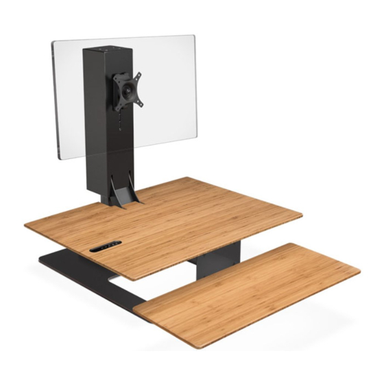
E7 Electric Standing Desk Converter Instructions
UDA115
Worksurface
Keyboard tray
Step 1
Place the base on your desk, with the front lined up with the front edge
of your desk. First (a) Attach the Lifting column to the Base using four (4)
M6x14 Flat head screws. Make sure the vertical column is facing towards
the front. Next, (b) Attach the Worksurface bracket to the front of the
Lifting column using four (4) M6x10 Pan head screws.
Step 2
Plug the Lifting column's cable into the Connecting cable, and plug the
Connecting cable into the Control box. Also, plug the Keypad and Power
cable into the Control box, and finally plug the Power cable into a 120
Vac wall outlet. Press the "up" arrow on the Keypad to raise the Work-
surface to a higher level for Steps 3 and 4.
Note: If surface does not rise perform the reset instructions
in the TROUBLESHOOTING section on page 4.
Step 3
Unplug the Keypad only! Feed the end of the Keypad's wire through
the top side of the Worksurface and fit the Keypad into the pocket as
shown. Press Keypad cable into the wire channel on the underside of
the Worksurface. Attach Worksurface onto the Worksurface bracket
using five (5) #10-24x5/8'' Pan head screws. Plug the Keypad back into
the Control box.
Step 4
Attach the Keyboard tray bracket to the Worksurface using four (4) #10-
24x5/8'' Pan head screws. Then attach the Keyboard tray to the Keyboard
tray bracket also using four (4) #10-24x5/8'' Pan head screws.
Caution: Make sure that Keyboard tray of the assembled unit is clear of the
desk edge. When the unit is at it's lowest position, the Keyboard tray will be
lower than the desk's surface.
Step 5
Take a moment to group your wires tightly together, to prevent them from
splaying too widely, getting caught in moving parts, or interfering in Step 6.
We recommend using the two (2) Cable clips with adhesive here:
(a) Above the Control box to keep the Power cord close to the Lifting
column. For additional securing, the cable can run behind the Control box.
(b) About 2'' below the Control box, on the top segment of the lifting column
(as shown). Leave slack to allow the lifting column to rise all the way up.
M5x10
#10-24x1/2''
Socket cap
VESA screw
Pan Head
Pan Head
VESA mount
VESA bracket
Slot cover
Keypad
[x] POWER CABLE
Power cable
[x] CONNECTING CABLE
(get from FRM200 instructions)
Connecting cable
M6x10
M5x10
#10-24x1/2''
Socket cap
Flat Head
Pan Head
Pan Head
Cable clips
(qty 2)
VESA screw
Pan head screws
(M6x14; qty 2)
Flat head screws
(M6x14; qty 8)
Pan head screws
(#10-24x5/8''; qty 13)
Pan head screws
(M6x10; qty 4)
Pan head screws
(M4x12; qty 4)
VESA screw
VESA screw
(qty 1)
UDA115/R01
Advertisement
Table of Contents

Subscribe to Our Youtube Channel
Related Manuals for Uplift Desk UDA115


Summary of Contents for Uplift Desk UDA115
- Page 1 (b) About 2’’ below the Control box, on the top segment of the lifting column (as shown). Leave slack to allow the lifting column to rise all the way up. © UPLIFT Desk • 1-800-349-3839 • info@upliftdesk.com • www.upliftdesk.com 90.014.01.0500v.C...
- Page 2 VESA screw which is provided with the VESA mount. (d) If you are not attaching a single or dual VESA mount to your UDA115 lifting column, you may attach the Slot cover with the two (2) M6x14 Pan head screws provided.
- Page 3 Note: While “RST” is still flashing, you can press the “2” button as many times as you’d like to toggle between the two settings. 4. Press the DOWN button until the unit lowers slightly, then rises slightly and the display changes back to the numeric height setting. UPLIFT Desk • 1-800-349-3839 • info@upliftdesk.com • www.upliftdesk.com...
-
Page 4: Troubleshooting
© are also available on the UPLIFT Desk website: upliftdesk.com. Excerpts or copies may not be forwarded to third parties or used in any other published form without the prior written consent of UPLIFT Desk. These instructions are subject to United States copyright law.
Need help?
Do you have a question about the UDA115 and is the answer not in the manual?
Questions and answers