Table of Contents
Advertisement
Quick Links
Advertisement
Table of Contents

Subscribe to Our Youtube Channel
Related Manuals for BLAUBERG Freshbox 100


Summary of Contents for BLAUBERG Freshbox 100
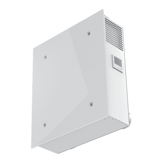
- Page 1 Air hAndling unit with heAt recovery Freshbox 100 uSer’S MAnuAl...
-
Page 2: Table Of Contents
Warranty card ....................................19 This user’s manual is a main operating document intended for technical, maintenance, and operating staff. The manual contains information about purpose, technical details, operating principle, design, and installation of the Freshbox 100 unit and all its modifications. - Page 3 Freshbox 100 www.blaubergventilatoren.de • Do not change the power cable length at your own discretion. Do not bend the power • Do not lay the power cable of the unit in cable. Avoid damaging the power cable. Do close proximity to heating equipment.
-
Page 4: Purpose
Freshbox 100 www.blaubergventilatoren.de PURPOSE Due to the ability to save heating energy by means of energy recovery, the unit is an important element of energy-efficient premises. The unit is a component part and is not designed for stand-alone operation. The unit is designed to ensure continuous mechanical air exchange in houses, offices, hotels, cafés, conference halls, and other utility and public spaces as well as to recover the heat energy contained in the air extracted from the premises to warm up the filtered stream of supply air. -
Page 5: Technical Data
IP44 for the unit motors The unit design is constantly being improved, thus some models may be slightly different from those described in this manual. TECHNICAL DATA Freshbox 100 Freshbox 100 ERV Maximum air capacity [m Unit voltage [V / Hz] 120/60... -
Page 6: Unit Design And Operating Principle
Freshbox 100 www.blaubergventilatoren.de UNIT DESIGN AND OPERATING PRINCIPLE Exhaust grille Exhaust spigot* Supply fan Supply air temperature sensor End switch Extract filter G4 F8 supply filter Lock Control panel Counter-flow heat exchanger Control unit Supply filter G4 Supply spigot Exhaust air duct... -
Page 7: Installation And Set-Up
Freshbox 100 www.blaubergventilatoren.de EXTRACT AIR EXTRACT AIR SUPPLY AIR SUPPLY AIR Extract spigot* INTAKE AIR INTAKE AIR EXHAUST AIR EXHAUST AIR INSTALLATION AND SET-UP READ THE USER'S MANUAL BEFORE INSTALLING THE UNIT. WHILE INSTALLING THE UNIT ENSURE CONVENIENT ACCESS FOR SUBSEQUENT MAINTENANCE AND REPAIR. - Page 8 Freshbox 100 www.blaubergventilatoren.de Mounting template ADDITIONAL HOLE! DRILL UPON CUSTOMER’S REQUEST ONLY! ADDITIONAL HOLE! DRILL UPON CUSTOMER’S REQUEST ONLY! Ø 130 mm (5 1/8") hole for Ø 100 mm (3 15/16") air ductFill the Ø 130 mm (5 / ") hole for Ø 100 mm (3 / ") air duct...
- Page 9 Freshbox 100 www.blaubergventilatoren.de 2. Remove the mounting template and drill two through holes Ø 105 mm (Ø 4 1/8”) for round air ducts. When mounting the unit with an additional extract spigot prepare a hole in the wall for a connecting bend and for laying of a rectangular air duct.
- Page 10 Freshbox 100 www.blaubergventilatoren.de 5. To install an additional extract spigot remove the plug on the rear part of the unit. Undo the screws, remove the plug and fix a spigot on its place using screws. 6. Insert the drain pipe and unit spigots into the corresponding wall-mounted air ducts.
-
Page 11: Connection To Power Mains
Freshbox 100 www.blaubergventilatoren.de CONNECTION TO POWER MAINS DISCONNECT THE UNIT FROM POWER MAINS PRIOR TO ANY OPERATIONS. THE UNIT MUST BE CONNECTED TO POWER MAINS BY A QUALIFIED ELECTRICIAN. THE RATED ELECTRICAL PARAMETERS OF THE UNIT ARE SHOWN ON THE RATING PLATE. -
Page 12: Unit Control
Freshbox 100 www.blaubergventilatoren.de UNIT CONTROL The unit is controlled by means of the control panel on the unit casing and of the remote control. Control panel Remote control Unit On/O Fan speed up Not available Not available : 88 Fan speed down... - Page 13 Freshbox 100 www.blaubergventilatoren.de 3. Timer. The timer is designed to switch the fans to maximum speed with subsequent automatic reset to a previous speed after a set time period, from 20 to 60 minutes. To turn the timer on/off: •...
- Page 14 Freshbox 100 www.blaubergventilatoren.de 6. Viewing the temperature sensor readings. To enter the Sensor Readings View mode turn the unit off. Then press on the control panel simultaneously and hold them down at least 3 seconds. The indicators light up in the Sensor Readings View mode.
- Page 15 Freshbox 100 www.blaubergventilatoren.de 10. Scheduled Operation mode setting. Each day of the week has four entries. Time of switching the unit to the set speed and turning the heater on or off can be set for each entry. • To enter the Scheduled Operation mode settings turn the unit off by pressing...
-
Page 16: Technical Maintenance
Freshbox 100 www.blaubergventilatoren.de 11. Alarms. In case of alarm the unit is turned off and the alarm indicators are displayed on the control panel. Temperature sensor Freeze protection malfunction sensor breakout ALARM INDICATION TROUBLESHOOTING Outdoor temperature Contact the Seller for sensor malfunction further information. -
Page 17: Troubleshooting
Freshbox 100 www.blaubergventilatoren.de 3. Fan maintenance (once a year). Even in case of regular maintenance of the filters, some dust may accumulate inside the fans and reduce the fan performance and supply air flow. Clean the fan with a cloth or a soft brush. Do not use water, aggressive solvents or sharp objects as they may damage the impeller. -
Page 18: Manufacturer's Warranty
Freshbox 100 www.blaubergventilatoren.de MANUFACTURER’S WARRANTY The product is in compliance with EU norms and standards on low voltage guidelines and electromagnetic compatibility. We hereby declare that the product complies with the provisions of Electromagnetic Council Directive 2014/30/EU, Low Voltage Directive 2014/35/ EU and CE-marking Directive 93/68/EEC. -
Page 19: Certificate Of Acceptance
This is to certify acceptance of the complete unit delivery with the user’s manual. The warranty terms are acknowledged and accepted. Customer’s Signature Seller’s Stamp INSTALLATION CERTIFICATE The Freshbox 100 unit has been connected to power mains pursuant to the requirements stated in the present user’s manual. Seller Address Phone Number Installation Technician’s Full Name... - Page 20 www.blaubergventilatoren.de BUSA73-5EN-04...
Need help?
Do you have a question about the Freshbox 100 and is the answer not in the manual?
Questions and answers