Table of Contents
Advertisement
DATASHEET
SIEMENS
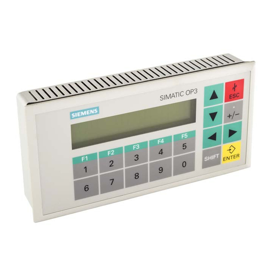
KEYPAD 6AV3503-1DB10
OTHER SYMBOLS:
KEYPAD6AV35031DB10, KEYPAD6AV3503 1DB10, KEYPAD6AV3503-1DB10, KEYPAD 6AV35031DB10, KEYPAD
6AV3503 1DB10, KEYPAD 6AV3503-1DB10
RGB ELEKTRONIKA AGACIAK CIACIEK
SPÓŁKA JAWNA
Jana Dlugosza 2-6 Street
51-162 Wrocław
Poland
biuro@rgbelektronika.pl
+48 71 325 15 05
www.rgbautomatyka.pl
www.rgbelektronika.pl
www.rgbelektronika.pl
www.rgbautomatyka.pl
Advertisement
Table of Contents

Related Manuals for Siemens SIMATIC HMI OP3


Summary of Contents for Siemens SIMATIC HMI OP3
- Page 1 DATASHEET SIEMENS KEYPAD 6AV3503-1DB10 OTHER SYMBOLS: KEYPAD6AV35031DB10, KEYPAD6AV3503 1DB10, KEYPAD6AV3503-1DB10, KEYPAD 6AV35031DB10, KEYPAD 6AV3503 1DB10, KEYPAD 6AV3503-1DB10 RGB ELEKTRONIKA AGACIAK CIACIEK SPÓŁKA JAWNA Jana Dlugosza 2-6 Street 51-162 Wrocław www.rgbelektronika.pl Poland biuro@rgbelektronika.pl +48 71 325 15 05 www.rgbautomatyka.pl www.rgbautomatyka.pl www.rgbelektronika.pl...
- Page 2 YOUR PARTNER IN MAINTENANCE Repair this product with RGB ELEKTRONIKA ORDER A DIAGNOSIS LINEAR ENCODERS SYSTEMS INDUSTRIAL COMPUTERS ENCODERS CONTROLS SERVO AMPLIFIERS MOTORS MACHINES OUR SERVICES POWER SUPPLIERS OPERATOR SERVO PANELS DRIVERS At our premises in Wrocław, we have a fully equipped servicing facility. Here we perform all the repair works and test each later sold unit.
- Page 3 Preface, Contents Part I Introduction SIMATIC HMI Part II Functions of the OP3 Operator Panel Equipment Manual Part III Installation and Commissioning Part IV Device Description, Test and Monitoring Functions Part V Appendices Glossary, Index 6AV3591–1AD00–1AB0 Release 11/99...
- Page 4 The approvals that apply to the device are detailed in the Chapter Technical Data. Trademarks The registered trademarks of Siemens AG are listed in the Preface. Some of the other designations used in these documents are also registered trademarks; the owner’s rights may be violated if they are used be third parties for their own purposes.
- Page 5 Preface Purpose This equipment manual provides operators, fitters, configurers and system support engineers with information about the functionality and technical design of the OP3. Organization of The equipment manual Operator Panel OP3 is organized into five parts: the manual Part Chapters Contents 1 - 2...
-
Page 6: Release
V 3.0 and later nual reviewed 11/99 Technical content of the equipment V 5.1 and later manual reviewed Trademarks The following names are registered trademarks of the Siemens AG: SIMATIC SIMATIC HMI ProTool ProTool/Lite ProTool/Pro SIMATIC Multi Panel SIMATIC Multifunctional Platform... - Page 7 Preface Other support In the case of technical queries, please contact your local Siemens in the sub- sidiaries and branches responsible for your area. SIMATIC Customer Available worldwide, at all times: Support Hotline Nuernberg Johnson City Singapur Simatic Basic Hotline...
- Page 8 Online Services concerning SIMATIC products through its Online services as follows: Up–to–date general information is provided – in Internet under http://www.ad.siemens.de/simatic – via Fax-Polling under 08765-93 02 77 95 00 Up–to–date product information and downloads for practical use can be found: –...
-
Page 9: Table Of Contents
Contents Part I INTRODUCTION Product Description ..........Configuration and Process Control Phases . - Page 10 Contents Displaying Messages ........Timers and Counters .
-
Page 11: Test And Monitoring Functions
Contents 15.3 Contrast Control ........15-4 Test and Monitoring Functions . - Page 12 Contents Operator Panel OP3 Edition 11/99...
-
Page 13: Part I Introduction
Part INTRODUCTION Product Description Functionality... - Page 14 Operator Panel OP3 Edition 11/99...
-
Page 15: Product Description
Product Description Using the OP3 The device SIMATIC HMI OP3 allows operating states and current process values of a connected SIMATIC S7 PLC to be visualized. In addition, inputs can be made on the OP3 and written to the PLC. Functions relating to machine diagnostics can also be executed on the OP3. - Page 16 Product Description Edit configuration data Configuration phase PC/PU Save configuration data Download configuration data Connection to SIMATIC S7 Process control SIMATIC S7 phase Figure 1-1 Configuration and Process Control Phases Static and If you wish to display text containing static and variable components, you variable sections must configure the variables and type in the static text as an explanation –...
-
Page 17: Configuration Of Op3
Product Description Configuration of OP3 Display, keyboard The keyboard and display are integrated in the top of the OP3. To the right, and connections you will find the connections for the of the OP3 24V power supply, MPI-connection, RS232-connection. Display System keyboard COROS OP3 MPI connection... - Page 18 Product Description Operator Panel OP3 Edition 11/99...
- Page 19 Functionality Functions and The table below shows the functions of the OP3 and their limit values. limit values Table 2-1 Functions of the OP3 OP3 Functions Display – Contrast control Using potentiometer Event messages – Maximum number – Maximum length (characters) –...
- Page 20 Functionality Table 2-1 Functions of the OP3 OP3 Functions Connection OP3 SIMATIC S7 – Number of PLCs that connect to a OP3 – Number of OP3s that connect to a S7-200 – Number of OP3s that connect to a S7-300 Operator Panel OP3 Edition 11/99...
-
Page 21: Part Ii Functions Of The Op3
Part FUNCTIONS OF THE OP3 General Operation Using the OP3 with Its Standard Functions Screens Password Protection Messages Timers and Counters STATUS VAR and FORCE VAR Functions with the OP3 System Settings on Standard Screens Process-Dependent Operator Guidance Communication... - Page 22 Operator Panel OP3 Edition 11/99...
-
Page 23: General Operation
General Operation System keyboard The OP3 is operated by means of the keyboard. The keyboard consists of the and keypad system keyboard and the keypad. Its configuration is shown in Figure 3-1. Keyboard The system keyboard and keypad functions are described below. Keys 1 – 5 Key functions on the key pad and the +/–... - Page 24 General Operation SHIFT key SHIFT Switch to the second function of the dual-assignment keys. To do this, the SHIFT key is pressed simultaneously with the other key concerned - for example: Decimal point : Press +/– SHIFT Soft-key function: Press SHIFT Sign key +/–...
-
Page 25: Shift For Digits And Soft Keys
General Operation In combination with SHIFT: : Scroll up in font. SHIFT : Scroll down in font. SHIFT SHIFT : Next position in an input field. : Previous position in an input field. SHIFT The numeric and arrow keys have a auto repeat function. If you keep a key pressed, your input is continually repeated after a short delay until you release the key. -
Page 26: Entering Values
General Operation Entering Values General procedure In input fields, values can be entered on the OP3 and transferred to the PLC. 1. Branch, as described in section 4.3, initially to the screen you require and then to the corresponding screen entry. 2. -
Page 27: Entering Numerical Values
General Operation 3.2.1 Entering Numerical Values Entering values In fields that allow the operator to enter a numerical value, you enter the with a decimal numerical value character by character on the keypad. point You enter a decimal point by pressing the SHIFT key and the sign key simultaneously. -
Page 28: Entering Alphanumeric Values
General Operation 3.2.2 Entering Alphanumeric Values Mixed input of In an input of alphanumeric values, digits and letters are mixed. digits and letters For the numerical components of the input, proceed as described in section 3.2.1. If, however, you wish to enter a letter at the current cursor position, you must enable the alphanumeric character set. -
Page 29: Using The Op3 With Its Standard Functions
Using the OP3 with Its Standard Functions Using the standard The configuration software ProTool, includes a configuration which contains screens standard screens. You can choose all the functions required for operating the OP3 by using these standard screens. The different functions are described in this manual with reference to the standard screens. - Page 30 Using the OP3 with Its Standard Functions Changing The change from screen level to message level, or back again, is either operating levels manual or automatic. Manual change You press the appropriate key and change the operating level from message level to screen level by pressing the ENTER key, from screen level to message level by pressing the ESCAPE key.
-
Page 31: Standard Screens
Using the OP3 with Its Standard Functions Standard Screens Basic operation The standard screens contain functions that are fundamental to the basic with standard operation of OP3, such as Display Screens, Modify Password and Set OP3 screens Operating Mode. Process-specific implementations, such as event messages or screens for the process, are not included. - Page 32 Using the OP3 with Its Standard Functions Main Screen Counter Screens Timer OPMode System Language Dat/Time StatVAR MPI Address ForceVAR Logout Password Edit Figure 4-2 Screen Hierarchy for the Standard Configurations Supplied Operator Panel OP3 Edition 11/99...
-
Page 33: Branching In Standard Screens
Using the OP3 with Its Standard Functions Branching in Standard Screens Branching to At screen level, you can operate and monitor the process or system by means screen level of the corresponding screens and standard screens and perform system set- tings. - Page 34 Using the OP3 with Its Standard Functions Operator Panel OP3 Edition 11/99...
-
Page 35: Screens
Screens Operator-process On the OP3, the process – for example, a bottling plant or a mixing unit – is monitoring and displayed on screens and controlled. These screens are configured by the control with configurer for specific users. screens On screens, logically associated process values are acquired and provide an overview of a process or system. -
Page 36: Screen Entries
Screens Screen Entries Displaying a Screens consist of one or more entries. On the OP3, precisely one entry is screen entry displayed per display page. Lines which have not been fully configured are displayed as blank lines. An example of a screen entry is Furnace1 temp. -
Page 37: Choosing Screens
Screens Choosing Screens Methods of You can choose a screen by means of soft keys and/or by using the screen choosing screens directory. Choosing with With soft keys, you can branch from one screen to another. soft key The branch is defined in the configuration. Choosing with Call the standard screen Screens. - Page 38 Screens Operator Panel OP3 Edition 11/99...
-
Page 39: Password Protection
Password Protection Preventing To prevent unauthorized operation of the OP3, there is the possibility of unauthorized controlling access by means of passwords and password levels for calling operation certain functions and inputs. Password Levels and Access Password When you are configuring on the OP3, you assign password levels from 0 to hierarchy 9 for soft keys and input fields. -
Page 40: Logging In And Out On The Op3
Password Protection Logging In and Out on the OP3 Login If a function is called on the OP3 for which the current password level is too low, you are automatically prompted on the display to enter the password. You terminate password input by pressing the ENTER key. Logout Choose the standard screen Password Logout to log out from the OP3. - Page 41 Password Protection Allocating You can allocate up to 20 passwords. The password must contain a minimum passwords and of three and a maximum of eight digits. Leading zeros and letters are not password levels allowed. To allocate a password and a password level, proceed as follows: 1.
- Page 42 Password Protection Operator Panel OP3 Edition 11/99...
-
Page 43: Messages
Messages Event messages Events and states in the control process are displayed on the OP3 in message and system form. A message consists of static text as a minimum. It may also contain messages variables. Different types of message are displayed on the OP3 event messages and system messages. - Page 44 Messages Message bit If there is a condition present in the current process that causes a message to procedure be issued – for example, a setpoint has been reached – a bit is set by the PLC application program in the data area for event messages. The OP3 reads the data area after a configured polling time.
-
Page 45: System Messages
Messages Stand-by message The stand-by message is event message No. 0. It appears on the display when the OP3 is working at message level and event messages or system messages are not waiting. The stand-by message is stored in the firmware and contains, by default, the release and the device type: Vx.xx 2x20 char. -
Page 46: Displaying Messages
Messages Displaying Messages Display Event messages are always output to the display at message level on the OP3 and are displayed according to display and message priorities. Messages are displayed one at a time on the OP3, even if they have been configured as single-line messages. - Page 47 Messages Scrolling through If a system message is not being displayed, you can scroll at message level Waiting Event through the messages that have not yet departed. Event messages are sorted Messages according to priority groups and are displayed in their order of arrival. Before you can scroll through waiting messages starting from the message being currently displayed, you must first go to scroll mode using the arrow keys:...
- Page 48 Messages Operator Panel OP3 Edition 11/99...
-
Page 49: Timers And Counters
Timers and Counters Standard screens With the OP3, you can access the SIMATIC S7’s timers and counters. Examples of this have been implemented on the OP3 standard screens. The following description of access to timers and counters refers to the Timer and Counter standard screens. -
Page 50: Timers
Timers and Counters Timers Display the actual For every timer that has been configured and enabled on the PLC, you can timer value have the OP3 display the present actual value. For this, call the Screens Timers standard screen. The following display appears, by way of an example: Timer actual value Timer selected... -
Page 51: Status Var And Force Var With The Op3
STATUS VAR and FORCE VAR with the OP3 Access to PLC With its PU functions STATUS VAR and FORCE VAR, the OP3 provides operand values means of displaying and modifying operand values supplied by a connected PLC by means of standard screens. In online mode, this means that PLC operands can be edited directly on the OP3 without having to connect a programming unit or a PC to the PLC. - Page 52 STATUS VAR and FORCE VAR with the OP3 Key functions After typing in the MPI address, you go to the operand field using the row key. Hold down SHIFT and select the data type you wish to have dis- arrow key. Pressing ENTER automatically sets the played using the corresponding data format in the format field.
-
Page 53: System Settings On Standard Screens
System Settings on Standard Screens In this chapter This chapter describes functions relating to system settings which can be executed by means of standard screens. 10.1 Selecting a Language Online selection of Messages and screens can be displayed in several languages. Up to three of three languages the languages listed below can be loaded simultaneously on the OP3 and presented to the operator for selection in online mode:... -
Page 54: Setting Date And Time
System Settings on Standard Screens 10.2 Setting Date and Time Changing the date You can adjust the current date and time on the OP3. The day of the week is and time calculated internally. Any change you make will affect all messages and screens from which a date or time variable is displayed. -
Page 55: Modifying The Address In Mpi Network Configuration
System Settings on Standard Screens Procedure To set the modes, proceed as follows: 1. Choose the standard screen System Mode. 2. Set the mode you require by means of a symbolic input. 3. After you confirm your input by pressing ENTER, a warm restart is performed. - Page 56 System Settings on Standard Screens Operator Panel OP3 10-4 Edition 11/99...
-
Page 57: Process-Dependent Operator Guidance
Process-Dependent Operator Guidance Soft keys and Different actions are normally required or allowed in different operating screen hierarchies situations. To support changing requirements during process control, you can configure the following measures, which provide the operator with help depending on the situation and aims: screen-dependent soft keys and user-defined screen hierarchies. -
Page 58: Self-Defined Screen Hierarchy
Process-Dependent Operator Guidance 11.2 Self-Defined Screen Hierarchy Defining the The screen hierarchy can be adapted to system-specific requirements and be screen hierarchy modified either in part or in whole. Screens can be removed or added. Screens can be linked together in random order. The configuration, sequence of the link, inclusion in the screen directory and the relevant cross-jump destinations are defined during configuration with ProTool/Lite. - Page 59 Process-Dependent Operator Guidance Example The OP3 is used to operate and monitor a system for producing and bottling different fruit juices. The system consists basically of a mixing unit and a bottling machine. Mixing unit The ingredients for the fruit juices are contained in three tanks. Depending on the juice that you wish to manufacture, ingredients are mixed in certain ratios.
-
Page 60: Evaluating Screen Numbers
Process-Dependent Operator Guidance 11.3 Evaluating Screen Numbers Application The screen number area is located on the PLC. The OP3 writes the number of the current screen to this area. If the PLC writes a screen number to the screen number area, the screen is opened on the OP3. You can configure operator guidance in this way. - Page 61 Process-Dependent Operator Guidance Special Screens If the most significant bit has been set in the data word (=1), the screen number refers to a special screen. If the most significant bit has not been set (=0), the screen is a user-defined screen. The screen numbers of the special screens are listed in the table below.
-
Page 62: System Keyboard Assignment
Process-Dependent Operator Guidance 11.4 System Keyboard Assignment Application Create a data area for your system keyboard on the PLC. When you press a key, the corresponding bit is set in the keyboard assignment. The bit is set for as long as the corresponding key is pressed. Releasing the key resets the bit. By an evaluation of this area, the operator’s attention can be drawn, for example, by means of an event message to incorrect operation of a key. -
Page 63: Communication
Communication Types of The OP3 can be connected to SIMATIC S7 automation systems (PLCs) via connection two different network configurations. The network configuration depends on the CPU being used. The following two types of connection are possible: SIMATIC S7-200 Point-to-Point Interface (PPI) SIMATIC S7-300 Multi-Point Interface (MPI) (without CPU318) -
Page 64: Connecting To An S7-200 Via The Ppi
Communication 12.1 Connecting to an S7-200 via the PPI Connection When you are connecting an OP3 to an S7-200, connect the OP3 to the S7-200’s PPI interface. In this particular instance, up to two S7-200s can be connected to the OP3. Similarly, you can connect several OP3s to a S7-200. -
Page 65: Connecting To An S7-300 Via The Mpi
Communication Interface If data user areas are used that are area located in the interface area, you must create an interface area. You must configure a separate interface area for each S7 connected. Settings With ProTool, all settings with the exception of the interface area must be in ProTool performed by choosing PLC. - Page 66 Communication Parameters The following parameters must be configured in the configuration software for a connection via the MPI: Address of the MPI address of the S7 module to which the OP3 communication is connected. The default address is 2. peer Expansion slot The number of the expansion slot containing the S7 module with which the OP3 exchanges data.
-
Page 67: Interface Area For The Simatic S7
Communication 12.3 Interface Area for the SIMATIC S7 Purpose The interface area is required only if it is intended that the following functions be used or evaluated by the SIMATIC S7: Sychronize the date and time of the S7 and the OP3 Evaluate the connection ID and Detect OP3 start-up in the S7 program. -
Page 68: Control And Response Bits
Communication 12.3.1 Control and Response Bits Purpose Three bytes are present in the interface area for the control and response bytes. Bytes n+0 and n+1 are used to synchronize the OP3 and the S7. Byte n+3 is not applicable to the OP3. Byte n+0: Byte n+0 is used by the OP3 to request the current time and the date from the Requesting... -
Page 69: Time And Date
Communication 12.3.3 Time and Date Purpose The current time and date are stored by the S7 program in bytes n+15 to n+17 and n+21 to n+24. This means that the OP3 can synchronize the time and date with the S7. Bytes Bytes n+15 to n+17 contain the current time of the S7 in BCD. - Page 70 Communication Reading the You then transfer the S7 CPU system time to OP3. The FC6 uses the OP3 S7 system time requirement in the interface area to set the OP clock. FC6 parameters: Parameter Address Type Description DBTDOP DB51 BLOCK_DB This is the interface area. Set_OPTime DB51.DBX0.2 BOOL The first word of DB51 contains the status and control bits which display...
- Page 71 Communication Network: 2 Enter PLC time in DAT_ZEIT CALL “READ_CLK” // with SFC 1 save SFC1 // PLC time –– Read System Clock RET_VAL :=#ret_val // in DAT_TIME :=#DAT_TIME Network: 3 Load time in OP3 #DBTDOP // Hours from DAT_TIME // in interface area byte 15 // Minutes from DAT_TIME // in interface area byte 16...
- Page 72 Communication FC 7 listing: Address Declaration Name Type Initial value Comment DBTDOP BLOCK_ Number of the interface area in_out NEW_ BOOL New date DATE bit from interface area. in_out NEW_ BOOL New time TIME bit from interface area. temp DAT_TIME DATE_ PLC time AND_...
- Page 73 Communication Network: 2 New date DAT OPN #DBTDOP CALL “READ_CLK” // read current time // SFC1 –– Read System Clock RET_VAL :=#ERROR_SFC :=#DAT_TIME DBB 21 // Load weekday from DBTDOP // in DAT_TIME DBB 22 // Load day from DBTDOP // in DAT_TIME DBB 23 // Load month from DBTDOP...
- Page 74 Communication Operator Panel OP3 12-12 Edition 11/99...
-
Page 75: Part Iii Installation And Commissioning
Part INSTALLATION AND COMMISSIONING Installation Commissioning... - Page 76 Operator Panel OP3 12-2 Edition 11/99...
-
Page 77: Installation
Installation Mounting location The OP3 is suitable for control cabinets and consoles. For this, the front and requirements panel must be provided with a mounting cutout (refer to section 15.1). The front panel must not be thicker than 4 mm. No other drilled holes are required for mounting. -
Page 78: Mechanical Installation
Installation 13.1 Mechanical Installation Installing the OP3 Insert the OP3 from the front into the prepared cutout. To do this, proceed as follows: 1. Remove three screws on the rear of the housing (Figure 13-1). 2. Pull the two sections of the housing carefully apart. 3. -
Page 79: Electrical Installation
Installation 13.2 Electrical Installation Electrical The OP3 requires electrical connections to the connections power supply, configuration computer (PC or programming unit), PLC. The electrical connection for the power supply is necessary only if the OP3 is not connected through the MPI interface to a SIMATIC S7 PLC. The electrical connection to the configuration computer is required only for transferring the configuration to the OP3. -
Page 80: Connecting The Configuration Computer
Installation 13.3 Connecting the Configuration Computer Connection Figure 13-2 shows you how to connect the OP3 to the configuration compu- configuration ter. The cabling of the connections shown in the figure are supplied with the diagram OP3. To download the configuration, you must first energize the OP3 by means of a plug-in power supply unit (refer to Section 15.2) or by using the 24V power supply cable supplied with it. -
Page 81: Connection To The Plc
Installation 13.4 Connection to the PLC Connection Figure 13-3 shows you how to connect the OP3 to the SIMATIC S7. configuration The cabling of the connections shown in the figure are supplied with the diagram OP3. When the OP3 is connected via an S7 bus connector (not supplied with the OP3), the OP3 must be energized by means of a plug-in power supply unit (refer to Section 15.2) or by using the 24V power supply cable supplied with No terminal resistor is required for the OP3. - Page 82 Installation Operator Panel OP3 13-6 Edition 11/99...
-
Page 83: Commissioning
Commissioning Diagrammatic Figure 14-1 shows the most important commissioning steps for initial startup, representation restarting and normal operation of the OP3. This is followed by an explanation of the different steps for taking the OP3 into service. Initial startup and restart Normal operation The OP3 should operate with a The OP3 is operated with an... - Page 84 Commissioning Initial During initial commissioning, the configuration required for operation is Commissioning downloaded from the configuration computer to the OP3. This can be done either by using the RS232 interface or the MPI. For the MPI, the configura- tion computer – that is, a PC or PU – must be equipped with an MPI card. When initially commissioning the OP3, proceed as follows: RS232 Connect the RS232 interface of...
- Page 85 Commissioning Recommissioning In recommissioning, the configuration loaded on the OP3 is replaced with another. This can be done either by using the RS232 interface or the MPI. For the MPI, the configuration computer – that is, a PC or PU – must be equipped with an MPI card.
- Page 86 Commissioning Operator Panel OP3 14-4 Edition 11/99...
-
Page 87: Part Iv Device Description, Test And Monitoring Functions
Part IV DEVICE DESCRIPTION, TEST AND MONITORING FUNCTIONS Device Description Test and Monitoring Functions... - Page 88 Operator Panel OP3 14-2 Edition 11/99...
- Page 89 Device Description In this chapter This chapter provides information about the dimensions of the OP3, the positions of the connection elements and manual adjustment of the display contrast. 15.1 Dimension Drawings Device and Figure 15-1 shows the dimension drawings of the OP3. mounting dimensions Front view...
-
Page 90: Connection Elements
Device Description 15.2 Connection Elements Positions of the The connections for the connection power supply, elements RS232 interface and MPI interface are located on the right side of the housing. The connection elements and their positions are illustrated in 15-2. MPI interface, 8-pin Power supply (SV) DC 24V RS232... - Page 91 Device Description Note If you require the hardware test (refer to Section 16) to test the RS232 inter- face, connect pins 3 and 4 to the 9-pin subminiature D connector of the serial transfer cable. The OP3 is connected to the RS232 interface of the PC by means of the cable supplied.
- Page 92 Device Description 2,5 m cable SIMATIC S7 Code M24V M24V RS485 line B RS485 line B RTSAS RTSAS P24V P24V RS485 line A RS485 line A Shield Figure 15-4 Configuration of the Interconnecting Cable 15.3 Contrast Control Adjusting the At the rear of the OP3, next to the symbol there is a countersunk display contrast potentiometer screw which is turned left or right to adjust the display...
- Page 93 Test and Monitoring Functions Hardware test Apart from a brief initial start test (”eprom test”, ”ram test”, ”flash test”), which is performed on every cold start of the OP3, a hardware test with test functions for all the important components of the device can be initiated by operator input.
-
Page 94: Edition
Test and Monitoring Functions CPU TEST The internal registers, timers and the interrupt controller of the processor are tested. RAM TEST The entire static RAM is ”read” tested and then ”write” tested, its previous contents being overwritten as a result. EPROM TEST The checksums of the memories are determined. -
Page 95: Part V Appendices
Part APPENDICES Brief Description of Standard Screens System Messages Technical Data ESD Guidelines SIMATIC HMI Documentation... - Page 96 Operator Panel OP3 Edition 11/99...
- Page 97 Brief Description of Standard Screens Overview The table below presents an overview of all the standard screens for the OP3. Apart from a brief comment on functions, mention is made of the requisite password level. The ”Level 1” column lists the screens that you can choose from the basic screen.
-
Page 98: A Brief Description Of Standard Screens
Brief Description of Standard Screens Operator Panel OP3 Edition 11/99... -
Page 99: System Messages
System Messages Message number System messages on the OP3 can be categorized in different ways. Information on the category to which a system message belongs is contained in the message number: Message number Message text Driver error Start-up message Warning Note Operating error Other message... - Page 100 System Messages Status messages The table below lists the status messages. Message Cause Action Please wait Mode in process of being changed Ready for Waiting for data from PU transfer or PC Data transfer Data being transferred bet- ween PU or PC and OP3 Firmware not Firmware cannot be used compatible...
- Page 101 System Messages Message Cause Action $ 005 Internal Error $ 006 Error in data transmission during MPI Check connection and re-send transfer (message with 1 variable) Internal error The connection to ProTool/Lite was disrupted Flash error (upon write) Flash is full (configuration too large) Flash error (upon delete) Wrong object number...
- Page 102 System Messages Message Cause Action $ 040 No response from PLC Check physical connection Cable defective or not plugged in $ 041 Temporary driver error Restart PC Re-send configuration $ 044 MPI transfer error $ 045 No connection to PLC No. x (message with variable ) $ 100 Invalid RAM contents...
- Page 103 System Messages Message Cause Action $ 404 Incorrect date input $ 409 Lower limit for input ignored Enter value greater than or equal to Var $ 410 Upper limit for input ignored Enter value smaller than or equal to Var $ 500 –...
- Page 104 System Messages Message Cause Action $ 620 Wrong parameter transferred in Download Repeat transfer of configuration mode $ 621 Wrong parameter transferred in Download Set required value by means of standard mode (message type) screen or the PLC $ 623 See Internal Errors $ 627 Incorrect configuration...
- Page 105 System Messages Message Cause Action $ 635 (Message with variable) Add to or modify configuration and repeat transfer Message or entry text not con- figured for current language Screen title not configured Invalid data format for symbo- lic field Invalid data format for setpoint Too many fields on process screen Variable does not exist for soft...
- Page 106 Put the OP3 during startup in Download mode, transfer the configuration again and restart the OP3 and the PLC. c) If the error continues to occur, please contact the nearest Siemens branch office. Report the number of the error that has occurred and any variable that may be included in the message.
-
Page 107: Technical Data
Technical Data Housing Front panel B D (mm) Mounting cutout B H (mm) 68 (DIN 43700) Useful depth approx. (mm) Protection type front IP65 rear IP20 Weight approx. (kg) 0,22 Processor Type 80C32 (Intel) Clock frequency 10.5 MHz Memory Flash memory for configuration data 128 KB SRAM working memory 128 KB... - Page 108 Technical Data Supply voltage Rated voltage +24 VDC Permissible range +15 ... +32 VDC Maximum permissible transients 35 V (500 ms) Time between two transients Min. of 50 sec. Current consumption 70 mA Average 110 mA at 24 V Max. continuous current 3 A, 10 µs (bei 30 V) Max.
-
Page 109: Esd Guidelines
ESD Guidelines In this chapter This chapter describes the most important precautions which must be taken to avoid damage toe the electrostatically sensitive devices in the OP3. What Does ESD Mean? Electrostatically Nearly all modern modules incorporate highly integrated MOS devices and sensitive devices components. -
Page 110: Important Precautions Against Charge
ESD Guidelines Important Precautions against Charge Keep away from Most plastics are capable of carrying high charges and it is therefore plastics imperative that they not be placed near sensitive components. Grounding When handling electrostatically sensitive devices, make sure people, workplaces and packaging are properly grounded. -
Page 111: Shipping Esds
ESD Guidelines Shipping ESDs Conductive As a matter of policy, modules and components should be stored and shipped packing only in conductive packing – for example, metalized plastic boxes, tin cans. Should packing not be conductive, modules must be conductively wrapped before they are packed. - Page 112 ESD Guidelines Operator Panel OP3 Edition 11/99...
-
Page 113: Simatic Hmi Documentation
SIMATIC HMI Documentation Target groups This manual is part of the SIMATIC HMI documentation. The documentation is aimed at the following target groups: Newcomers Users Configurers Programmers Commissioning engineers How the documentation is organized The SIMATIC HMI documentation consists of the following components: User’s Guides for: –... - Page 114 Documentation Target Group Content First Steps with ProTool Newcomers This documentation guides you step by step through the configuration of Product Brief a screen with various objects changing from one screen to another a message. This documentation is available for: OP 3, OP 5, OP 7, OP 15, OP 17 OP 25, OP 27, OP 35, OP 37, TP 27, TP 37 Windows-based systems...
- Page 115 Documentation Target Group Content Application Example Newcomers ProTool is supplied with example configurations and the corresponding PLC programs. This documentation describes Start-up Guide how you load the examples onto the operating unit and PLC run the examples and upgrade the connection to the PLC to suit your own specific application.
- Page 116 Documentation Target Group Content Communication Programmers Provides information on connecting text-based and graphics displays to the following PLCs: User’s Guide SIMATIC S5 SIMATIC S7 SIMATIC 500/505 drivers for other PLCs This documentation describes the configuration and parameters required for connecting the devices to the PLC and the network user data areas used for exchanging data between operating unit and PLC.
-
Page 117: Glossary
Glossary Area pointer Required for enabling data transfer between the OP3 and the PLC. It contains details of the location and size of data areas in the PLC. Arrival of a The time at which a message is initiated by the PLC or OP3. message Configuration Definition of system-specific basic settings, messages and screens using... - Page 118 Glossary Fields Reserved areas in configured or permanent texts, used to output and/or input certain values. Flash memory Programmable memory which can be deleted quickly and then re–written. Function Prompts the OP3 to work by choosing it – for example, Delete Buffer. Function screen A screen stored in the firmware.
- Page 119 Glossary Screen Form of presenting logically associated process data which can be displayed collectively on the OP3 and modified individually. Screen entry Element of a screen; consists of an entry number, texts and variables. Screen level Editing level of the OP3 at which screens can be monitored and manipulated Selection field Field for for setting values of parameters (one of several defined values can be chosen).
- Page 120 Glossary Operator Panel OP3 Glossary-4 Edition 11/99...
-
Page 121: Index
Index Choose language, A-1 Access permissions, 6-1 screens, 4-5 Access protection, 6-1 Clock frequency, C-1 Actual value, 5-2 Cold start, 16-1 Actual–value display, 2-1 COM1/2, 14-2, 14-3 Address Combined I/O, 5-2 OP3, 12-2 Commissioning, 14-1 S7, 12-2 Communication, 2-1, 12-1 Address area, event messages, 7-2 Configuration, 1-3, Glossary-1 Address modification in MPI network configu-... - Page 122 Index Depth, C-1 Device description, 15-1 Field entries, undo, 3-2 Device type, 7-3 Fields, 5-2, Glossary-2 Diagnostic function, 2-1 I/O fields, 5-2 Digits / soft keys, assign, 3-3 actual value, 5-2 Dimension drawings, 15-1 date, 5-2 Directory, screens, 4-3 setpoint, 5-2 Discharge, static , C-2 time, 5-2 Display, 1-3, 2-1, C-1...
- Page 123 Index Incorrect input, canceling, 3-4 Inhibiting, system messages, 7-3 Languages, 2-1 Initial commissioning, 14-2 select, 10-1, A-1 Initial startup, 14-1 LCD display, 1-3 Input Left–justified input, 3-5 alphanumeric values, 3-6 Letter input, 3-6 left–justified, 3-5 Limit value check, 2-1, 3-5 letters, 3-6 Literature, E-1 numerical values, 3-5...
- Page 124 Index Mounting dimensions, 15-1 Password, A-1, Glossary-2 MPI, 2-1 allocating, 6-3 address, 9-1, 12-4 construction, 6-3 card, 14-2 deleting, 6-3 connecting cable, 14-2, 14-3 format, 6-3 connection, 1-3 index, 6-2 connection via, 14-2 level, 2-1, 6-1, 6-2, 6-3, A-1, Glossary-2 interface, 14-2, 14-3, 15-3 list, 6-2 network configuration, modifying address,...
- Page 125 Index RS232 SHIFT key, 3-2 connection, 1-3 Shipping, ESD assemblies, D-3 interface, 14-2, 14-3 Shorting plug, 16-2 Test, 16-2 Sign key, 3-2 Signal lines, 13-3 SIMATIC HMI documentation, E-1 SIMATIC S7 connection interface area, 12-5 S7 configuration, 12-3 S7–200 via PPI, 12-2 S7 data formats, 9-2 S7–300 via MPI, 12-3 S7 data types, 9-2...
- Page 126 Index Test functions, 16-1 Updating TEST_ALL, 16-2 messages, 7-2 Text instead of a value, 3-6 PLC operands, 9-2 Time screen entries, 5-2 adjust, A-1 User data areas, 12-1 and date, 12-6, 12-7 in messages, 7-1 setting, 10-2 Time base, 8-2 V.24, Test, 16-2 Timer, 2-1, A-1 Value field, 9-1...