Advertisement
WARNING: SmartWitness installations should be performed by a qualified individual or installation professional
only. Working with a vehicle's power system can be dangerous to both you and your vehicle. This installation is
intended only to be a guide since vehicle designs and power/input sources can vary significantly
from vehicle to vehicle.
If you need to schedule a professional installation service in the USA for your
SmartWitness device(s), please visit
All cellular-enabled CP4 devices must use the installation wizard for proper onboarding and activation, please
visit
http://install.smartwitness.com
CP4
Wi-Fi/LTE enabled 4 Channel HD Recorder
Installation Guide
v1.1
http://smartwitness.com/scheduleinstall
to register, login, and use the SmartInstall wizard.
and submit the online form.
Advertisement
Table of Contents

Subscribe to Our Youtube Channel
Related Manuals for SmartWitness CP4

Summary of Contents for SmartWitness CP4
-
Page 1: Installation Guide
If you need to schedule a professional installation service in the USA for your SmartWitness device(s), please visit http://smartwitness.com/scheduleinstall and submit the online form. All cellular-enabled CP4 devices must use the installation wizard for proper onboarding and activation, please visit http://install.smartwitness.com to register, login, and use the SmartInstall wizard. - Page 2 CP4 features 4 camera inputs for connecting 1, 2, 3, or 4 cameras. A 6-Axis G-Sensor, Microphone, SD card (up to 128GB capacity), panic button, cellular modem, &...
- Page 3 Built-in temperature logic for improved recording for up to 24 hours after ignition off. performance in high-temp environments. Adjustable Resolution & Frame Rate. Built-in Auto SD card format feature. CP4 automatically G-Shock Sensor and Gyro (adjustable detects SD error/corruption and auto-formats sensitivity).
- Page 4 Product Name Image CP4 Vehicle Recorder Power Cable BAT(+), IGN+, BAT(-) Remote Controller (Panic Button) with 3M adhesive Audio/Video Output Cable Camera Input Cable (4x Aviator input for Ch. 1-4) GPS Antenna Module Wire Splice clip & Velcro Sticker pg. 4...
- Page 5 Locking Enclosure/Mounting Bracket (Optional Accessory) External LTE Modem + Antenna (Optional Accessory) External WiFi/LTE Modem (Optional Accessory) 2. CP4 Hardware Overview Dimensions Built-in microphone pg. 5...
-
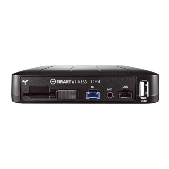
Page 6: Front View
Rear View 3. Installation: Park the vehicle on a flat service. Turn of the engine before installing the CP4. Insert the provided SD card into the SD card memory slot, and lock the SD card by sliding the SD locking switch. - Page 7 Install all the interior and exterior cameras with 3M dual sided adhesive or hard mounting screws (confirm with customer as to the desired installation method). o All the four cameras will be connected to the CP4 recorder via the Camera Input Cable.
-
Page 8: Camera Types
Run camera cable(s) and secure in headliner or other area so no cables are exposed. Use provided wire clips if necessary. Connect all cables to CP4 Recorder. Secure the windshield mounted camera cables into the headliner and down the A-Pillar. - Page 9 (outside) Camera Channel inputs o CP4 has some restrictions on which cameras can be connected to which channel inputs. 1. You cannot connect an “-A” camera to channel 4 2. Ch 2 & 3 must have the same camera type (either both “-C”...
-
Page 10: Power Connection
Channel 3 Channel 4 4. CP4 Power Cable and Wiring Lay out the power cable roughly where it will run once hidden behind the vehicle's interior panels. This gives you an idea of where to route the cable and how much slack to leave on the way down to the vehicle’s power source. - Page 11 Rear View b. Inside View 6. Connecting a WiFi or Cellular Modem (Optional) o After bootup, the CP4 remote should have a solid blue and green LED to indicate network connection. Wifi/LTE modem type 1 (Connecting to USB1 port on the CP4 rear panel) pg.
- Page 12 If customer or TSP is bringing their own sim, then the SIM may first need to be inserted. If no SIM is provided, then it may be a SmartWitness provided SIM. In this case, the SIM will already be inserted.
-
Page 13: G-Sensor Calibration
After installation of the CP4 and accessories into the vehicle you can turn on the ignition and CP4 recorder will power on. There will be a sequence of red, blue & green LED lights on the Remote/Panic Button during the boot-up process. -
Page 14: Troubleshooting
9. Troubleshooting The CP4 has a solid red light on as well as solid green and blue. o Solid red LED indicates that one of the connected cameras is not receiving view signal. Please check the camera’s connection. The CP4 red LED is blinking o There is an SD card error/corruption. - Page 15 pg. 15...
Need help?
Do you have a question about the CP4 and is the answer not in the manual?
Questions and answers