Table of Contents
Advertisement
Quick Links
Advertisement
Table of Contents

Subscribe to Our Youtube Channel
Related Manuals for Vertiv Avocent AutoView 2108


Summary of Contents for Vertiv Avocent AutoView 2108
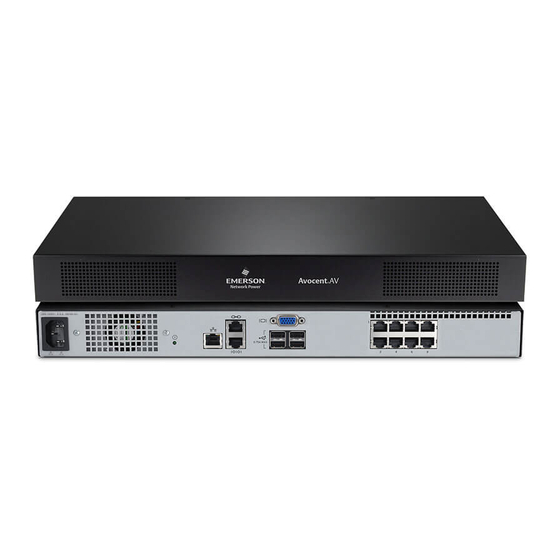
- Page 1 Avocent® AutoView™ 2108/2216 Switch for Dell® Installer/User Guide...
- Page 2 The products covered by this instruction manual are manufactured and/or sold by Vertiv This document is the property of Vertiv and contains confidential and proprietary information owned by Vertiv. Any copying, use or disclosure of it without the written permission of Vertiv is strictly prohibited.
-
Page 3: Table Of Contents
TABLE OF CONTENTS 1 Product Overview 1.1 Features and Benefits 1.1.1 Reduce cable bulk 1.1.2 IQ modules 1.1.3 Multiplatform support 1.1.4 User interfaces 1.1.5 Virtual media and smart card-capable switches 1.1.6 IPv4 and IPv6 capabilities 1.1.7 Access the AutoView switch for Dell using a standard TCP/IP network 1.1.8 Upgradeable 1.1.9 Two-tier expansion 1.1.10 Remote Access Key (RAK) - Page 4 4.13 DSView™ Software Settings 4.14 Active Sessions 4.15 Closing a Session 5 KVM Video Viewer 5.1 Virtual Media Sessions 5.2 KVM Session 5.3 Performance Errors 5.4 Java Versions 5.5 Opening a KVM Session Vertiv™ | Avocent® AutoView ™ Switch for Dell Installer/User Guide...
- Page 5 5.6 Saving the View 5.7 Pasting Text 5.8 Closing a KVM Video Viewer Session 5.9 KVM Video Viewer Profile Settings 5.9.1 Refresh 5.9.2 Fit 5.9.3 Full Screen 5.9.4 Mini-Mode 5.9.5 Scaling 5.9.6 Color Modes 5.9.7 Session User List 5.9.8 Status Bar 5.10 Macros 5.10.1 Global Macros 5.11 Virtual Media...
- Page 6 Appendix B: Setup Port Pinouts Appendix C: Using Avocent Serial IQ Modules Appendix D: Sun Advanced Key Emulation Appendix E: UTP Cabling Appendix F: Technical Specifications Appendix G: KVM Session Optimization Vertiv™ | Avocent® AutoView ™ Switch for Dell Installer/User Guide...
-
Page 7: Product Overview
1 PRODUCT OVERVIEW The Avocent® AutoView™ 2108/2216 Switch for Dell® is an analog keyboard, video and mouse (KVM) switch that provides flexible, centralized local access to data center servers. It can also provide centralized remote access to data center servers when used in conjunction with the optional Remote Access Key (RAK). -
Page 8: Virtual Media And Smart Card-Capable Switches
By typing Help in the password dialog, you are directed to Vertiv™ Technical Support. Recommended usage for the switch is in a data center infrastructure protected by a firewall. -
Page 9: Two-Tier Expansion
1.1.9 Two-tier expansion The switch allows you to tier one additional switch from each ARI port on the primary switch. Each tiered switch is attached in the same manner as any device. This additional tier of units allows you to attach up to 512 servers in one system. -
Page 10: Lan Related Precautions
1.4 LAN Related Precautions • Do not connect or use during a lightning storm. There can be a risk of electrical shock from lightning. • Never connect or use in a wet environment. Vertiv™ | Avocent® AutoView ™ Switch for Dell Installer/User Guide... -
Page 11: Installation
2 INSTALLATION The switch uses TCP/IP for communication over Ethernet. For the best system performance, use a dedicated, switched 100BaseT network. You can also use 10BaseT Ethernet. You can use the terminal software, OSCAR™ interface or the OBWI to manage your switch system. The OBWI manages a single switch and its connections. - Page 12 Figure 2.1 Basic Configuration Vertiv™ | Avocent® AutoView ™ Switch for Dell Installer/User Guide...
- Page 13 Table 2.1 Basic Configuration Descriptions ITEM DESCRIPTION ITEM DESCRIPTION AutoView Switch for Dell (16-Port Model Shown) ACI Connection Power Cord External Virtual Media - USB Connections Analog Users (2) Target Device Ports Digital User (requires the RAK) IQ modules LAN/Network Servers/Target Devices 10101 Console Setup Port NOTE: The switch supports connecting to another appliance via an ACI connection.
-
Page 14: Tiering Your Switch Using An Iq Module
4. Connect the other end of the CAT5 cable to the desired ARI port on the back of your switch. 5. Repeat steps 2-4 for all devices you wish to attach. NOTE: Turn off the switch before servicing. Always disconnect the jumper cord from the power source. Vertiv™ | Avocent® AutoView ™ Switch for Dell Installer/User Guide... -
Page 15: Adding A Tiered Switch
Figure 2.2 IQ Module Connection Table 2.2 IQ Module Connection Descriptions ITEM DESCRIPTION CAT5 USB Connection VGA Connection 2.4.1 Adding a tiered switch NOTE: The switch does not support the Avocent® OutLook EL80-DT KVM switch. You can tier up to two levels of switches, enabling users to connect to up to 512 devices. In a tiered system, each device port on the main switch will connect to the ACI port on each tiered switch. - Page 16 NOTE: The switch supports one tiered switch per device port of the main switch. You cannot attach a switch to the tiered switch. Figure 2.3 Tiering the Switch With a UTP Analog Switch Vertiv™ | Avocent® AutoView ™ Switch for Dell Installer/User Guide...
-
Page 17: Adding A Tiered Legacy Switch
Table 2.3 Tiering the Switch With a UTP Analog Switch Descriptions ITEM DESCRIPTION Local User ARI Connection UTP Connection ACI Connection (chain icon) 2.4.2 Adding a tiered legacy switch The following figure illustrates a tiered legacy switch configuration. To add a legacy switch (optional): Mount the switch into your rack. - Page 18 Figure 2.4 Tiering Legacy Switches Vertiv™ | Avocent® AutoView ™ Switch for Dell Installer/User Guide...
-
Page 19: Configuring Your Switch
Table 2.4 Descriptions for Tiering Legacy Switches ITEM DESCRIPTION Local User ARI Connection IQ module PS2 Connection Target Device Connection 2.5 Configuring Your Switch Once all physical connections have been made, you will need to configure the switch for use in the overall switch system. -
Page 20: Verifying Power Status
Before a computer connected to the switch can be used for remote user control, you must set the mouse speed and turn off acceleration. For machines running Microsoft® Windows® (Windows NT®, 2000, XP or Server 2003), use the default USB mouse driver. Vertiv™ | Avocent® AutoView ™ Switch for Dell Installer/User Guide... - Page 21 To ensure that the local mouse movement and remote cursor display remain in sync, mouse acceleration must be set to none for all user accounts accessing a remote system through a KVM switch. Mouse acceleration must also be set to none on every remote system. Special cursors should not be used and cursor visibility options, such as pointer trails, Ctrl key cursor location animations, cursor shadowing and cursor hiding, should also be turned off.
- Page 22 This page intentionally left blank Vertiv™ | Avocent® AutoView ™ Switch for Dell Installer/User Guide...
-
Page 23: Local Oscar™ User Interface
3 LOCAL OSCAR™ USER INTERFACE The AutoView™ switch for Dell® features user-side keyboard and mouse ports that allow you to connect a USB keyboard and mouse for direct analog access. The switch uses the OSCAR™ interface to configure your system and devices. You can also use the OSCAR interface to access devices that are attached to the AutoView switch for Dell. -
Page 24: Viewing Switch System Status
3.1.2 Viewing switch system status The status of devices in your system is indicated in the right column of the Main dialog box. The following table describes the status symbols. Vertiv™ | Avocent® AutoView ™ Switch for Dell Installer/User Guide... -
Page 25: Selecting Devices
Table 3.2 OSCAR Interface Status Symbols SYMBOL DESCRIPTION (green circle) device connected, turned on and the IQ module is online. Connected device is turned off or is not operating properly and the IQ module is offline. Connected switch is online. Connected switch is offline or not operating properly. -
Page 26: Soft Switching
To switch back to the previous device, press Print Screen and then Backspace. 3.1.5 Navigating the OSCAR interface The following table describes how to navigate the OSCAR interface using the keyboard and mouse. Vertiv™ | Avocent® AutoView ™ Switch for Dell Installer/User Guide... -
Page 27: Connecting Local Virtual Media
Table 3.3 OSCAR™ Interface Navigation Basics KEYSTROKE COMBINATION FUNCTION OSCAR interface activation sequence. By default, Print Screen and Ctrl+Ctrl are set as Print Screen, Ctrl+Ctrl, Shift+Shift and/or the OSCAR interface activation options. Shift+Shift and Alt+Alt must be set within the Alt+Alt OSCAR interface before use. -
Page 28: Setup Dialog Box Functions
To access the OSCAR interface Menu dialog box, activate the OSCAR interface and click Setup - Menu in the Main dialog box. To choose the display order of devices: Select Name to display devices alphabetically by name. -or- Select EID to display devices numerically by EID number. Vertiv™ | Avocent® AutoView ™ Switch for Dell Installer/User Guide... -
Page 29: Controlling The Status Flag
-or- Select Port to display devices numerically by port number. 2. Click OK. Depending on the display method selected, the corresponding button is depressed in the Main dialog box. To change how the OSCAR™ interface is invoked: Select the checkbox next to one of the listed methods. 2. -
Page 30: Setting The Keyboard Country Code
You can toggle between displaying the name or the EID number of each IQ module, so even if you move the IQ module/device to another port, the name and configuration is recognized by the switch. Vertiv™ | Avocent® AutoView ™ Switch for Dell Installer/User Guide... -
Page 31: Configuring Network Settings
NOTE: When it is initially connected, a device will not appear in the Names list until it is turned on. Once an initial connection has been made, it appears in the Names list even when turned off. To access the OSCAR interface Names dialog box, activate the OSCAR interface and click Setup - Names. NOTE: If new IQ modules are discovered by the switch, the on-screen list is automatically updated. -
Page 32: Selecting Devices For Scan Mode
2. Select Scan Enable in the Commands dialog box. Scanning begins. 3. Click X to close the Commands dialog box. To cancel Scan mode: Select a device if the OSCAR interface is open. Vertiv™ | Avocent® AutoView ™ Switch for Dell Installer/User Guide... -
Page 33: Viewing And Disconnecting User Connections
-or- Move the mouse or press any key on the keyboard if the OSCAR interface is not open. Scanning will stop at the currently selected device. -or- From the Commands dialog box, clear the Scan Enable checkbox. 3.3.3 Viewing and disconnecting user connections You can view and disconnect users through the User Status dialog box. - Page 34 3. Click OK to restore factory defaults. You will see the IQ module go offline briefly and return. - or- Click X or press Escape to cancel the operation. 4. Click X to close the IQ Select dialog box. Vertiv™ | Avocent® AutoView ™ Switch for Dell Installer/User Guide...
-
Page 35: Obwi Operation
4 OBWI OPERATION The OBWI for the AutoView™ switch for Dell® is a remote, web browser-based user interface. For details on setting up your system, see Connecting the AutoView™ Switch for Dell® Hardware on page 5. The following table lists the operating systems and browsers that are supported by the OBWI. Make sure that you are using the latest version of your web browser. -
Page 36: Using The Obwi
Content area: Use the content area to display or make changes to the switch OBWI system. 4.2 Viewing System Information You can view switch and target device information from the following screens in the user interface. Vertiv™ | Avocent® AutoView ™ Switch for Dell Installer/User Guide... -
Page 37: Generating A Certificate
Table 4.3 System Information CATEGORY SELECT THIS: TO VIEW THIS: List of connected devices, as well as the name, type, status and action of each device. Click on a target device to view the Target Devices Unit View - Target Devices following information: name, type, EID, available session option and the connection path. -
Page 38: Tools - Rebooting And Upgrading
IQ adaptor sessions. A target device experiencing an IQ adaptor firmware update can not display or can display as disconnected. The target device appears normally when the update is completed. Vertiv™ | Avocent® AutoView ™ Switch for Dell Installer/User Guide... -
Page 39: Saving And Restoring Configurations And User Databases
CAUTION: Disconnecting an IQ adaptor during a firmware update or cycling power to the target device will render the module inoperable and require the IQ adaptor to be returned to the factory for repair. To upgrade the switch firmware: From the side navigation bar, click Unit View - Appliance - Overview to open the Unit Maintenance screen. -
Page 40: Property Identity And Location Settings
NOTE: Only administrators can make changes to the Network dialog box settings. Other users will have view only access. From the side navigation bar, click Network to display the General, IPv4 and IPv6 tabs. Vertiv™ | Avocent® AutoView ™ Switch for Dell Installer/User Guide... -
Page 41: Snmp Settings
To configure general network settings: Click the Network tab, then click the General tab to display the switch General Network Settings screen. 2. Select one of the following options from the LAN Speed drop-down menu: Auto-Detect, 10 Mbps Half Duplex, 10 Mbps Full Duplex, 100 Mbps Half Duplex or 100 Mbps Full Duplex. NOTE: You must reboot if you change the Ethernet mode. -
Page 42: Auditing Event Settings
To delete an offline IQ adaptor: From the side navigation bar, click Ports - IQ adaptors to open the IQ adaptor screen. 2. Click in the applicable IQ adaptor checkbox. 3. Click Delete Offline. Vertiv™ | Avocent® AutoView ™ Switch for Dell Installer/User Guide... -
Page 43: Upgrading Iq Adaptors
4.11.2 Upgrading IQ adaptors The IQ adaptors will automatically update when the switch is updated. To update your switch firmware, Tools - Rebooting and Upgrading on page 32 or the DSView management software Online Help. If issues occur during the normal upgrade process, IQ adaptors can also be force-upgraded when needed. NOTE: Check http://www.VertivCo.com/en-us/support/ for firmware upgrade files. -
Page 44: Local User Account Settings
5. Select any of the available devices that you wish to assign to the user account and click Add. NOTE: User Administrators and Appliance Administrators can access all devices. 6. Click Save. Vertiv™ | Avocent® AutoView ™ Switch for Dell Installer/User Guide... -
Page 45: Virtual Media Session Settings
To delete a user account (User Administrator or Appliance Administrator only): From the side navigation bar, select User Accounts - Local Accounts to open the Local User Accounts screen. 2. Click the checkbox to the left of each account that you wish to delete, then click Delete. To edit a user account (Administrator or active user only): From the side navigation bar, select User Accounts - Local Accounts. -
Page 46: Dsview™ Software Settings
NOTE: If there is an associated locked virtual media session, it is disconnected. To close a session (local users only): From the side navigation bar, select Local Session. 2. Select the Disconnect Active Session checkbox. Vertiv™ | Avocent® AutoView ™ Switch for Dell Installer/User Guide... -
Page 47: Kvm Video Viewer
5 KVM VIDEO VIEWER The KVM Video Viewer is used to conduct a KVM session with one or more target devices attached to one or more KVM switches. You can optionally use KVM session profiles to control session behavior on target devices. When you connect to a device using the KVM Video Viewer, the target device desktop appears in a separate window. -
Page 48: Opening A Kvm Session
Modes, Session User List and Status. NOTE: Each of the settings in this section can be accessed from the View tab of the KVM Video Viewer menu. 5.9.1 Refresh The Refresh setting enables background refresh. Vertiv™ | Avocent® AutoView ™ Switch for Dell Installer/User Guide... -
Page 49: Fit
To update the Video Viewer window: Click View - Refresh. 5.9.2 Fit To resize the KVM Video Viewer window for digitized video: Click View - Fit. 2. Select the Fit menu item from the View menu to resize the Viewer window to the size needed to completely display the resolution of the digitized video. -
Page 50: Scaling
To view active users of this session: Click View - Session User List. 5.9.8 Status Bar To display or hide the status bar at the bottom of the Viewer window: Click View - Status Bar. Vertiv™ | Avocent® AutoView ™ Switch for Dell Installer/User Guide... -
Page 51: Macros
5.10 Macros The KVM Video Viewer window macro function allows you to: • Send multiple keystrokes to a device, including keystrokes that you cannot generate without affecting your local system, such as Ctrl-Alt-Delete. • Send a macro from a predefined macro group. Macro groups for Windows®, Linux® and Sun are already defined. - Page 52 NOTE: Click Remove to remove the highlighted keystroke or click Reset to reset the macro. You can also re-arrange the order of the keystrokes by clicking Move Up or Move Down. 5. When finished, click OK. Vertiv™ | Avocent® AutoView ™ Switch for Dell Installer/User Guide...
-
Page 53: Virtual Media
To edit a macro: Click on the name of the macro you want to edit and click Edit. 2. Make changes as desired and click OK. To delete a macro: Click on the name of the macro you want to delete and click Delete. 2. - Page 54 2. The Details box appears. Click USB Reset. 3. A warning message appears, indicating the possible effects of the reset. Confirm or cancel the reset. 4. To close the Details box, click Details again. Vertiv™ | Avocent® AutoView ™ Switch for Dell Installer/User Guide...
-
Page 55: Creating An Image
5.11.2 Creating an image You can create an image file from a source file folder. The created image can then be mapped. You can also add an image file. To create or add an image: Select Virtual Media - Create Image from the KVM Video Viewer menu. 2. -
Page 56: Mouse Synchronization
Generally, the Video Viewer window automatic adjustment feature optimizes the video for the best possible view. However, you can fine-tune the video with the help of Vertiv™ Technical Support, by clicking Manual Video Adjust from the Tools tab of the Video Viewer window. You can also verify the level of packets per second required to support a static screen by observing the packet rate located in the lower left-hand corner of the dialog box. - Page 57 Block Noise Threshold To manually adjust the video quality of the window: NOTE: The following video adjustments should be made only with the help of Vertiv™ Technical Support. Click Tools - Manual Video Adjust from the Video Viewer window menu.
-
Page 58: Cursor Commands
Once a smart card has been mapped, the card is displayed at the bottom of the Tools tab along with a checkmark indicating it has been mapped. If supported by the target server, an icon can also be displayed showing whether the smart card is mapped, not mapped or disabled. Vertiv™ | Avocent® AutoView ™ Switch for Dell Installer/User Guide... -
Page 59: Video Recording
5.14.1 Video Recording The KVM Video Viewer contains a built-in video recorder and player. The recorder is essentially two recorders as it can record continuously and persistently. Continuous recording The continuous recorder can operate at all times a KVM session is in progress. It stores KVM video in periods of 30 seconds up to a maximum of either 30 minutes or the configured maximum disk space. - Page 60 Select Tools - Export Video from the KVM Video Viewer menu. 2. Browse for the source file. 3. Browse for the exported file. 4. Use the drop-down menu to select the resolution. 5. Click Export. Vertiv™ | Avocent® AutoView ™ Switch for Dell Installer/User Guide...
-
Page 61: Terminal Operation
6 TERMINAL OPERATION Each switch can be configured at the switch level through the Terminal Console menu interface, which is accessed through the 10101 setup port. All terminal commands are accessed through a terminal screen or a PC running terminal emulation software. NOTE: The preferred method is to make all configuration settings in the local UI. -
Page 62: Other Console Main Menu Options
This menu selection will return you to the ready prompt. If the Console menu interface password is enabled, you must exit the Console Main menu so that the next user is prompted with the Password login screen. Vertiv™ | Avocent® AutoView ™ Switch for Dell Installer/User Guide... -
Page 63: Appendices
APPENDICES Appendix A: MIB SNMP Traps The switch has the ability to send audit events to an SNMP Manager. The SNMP traps are defined in an SNMP Trap MIB. The Trap MIB file can be uploaded from the switch using the Save Trap MIB function. The uploaded Trap MIB file can then be loaded into an SNMP Trap Receiver application. - Page 64 IQ module Image Upgrade Result IQ module Restarted Virtual Media Session Started Virtual Media Session Stopped Virtual Media Session Terminated Virtual Media Session Reserved Virtual Media Session Unreserved Virtual Media Session Mapped Vertiv™ | Avocent® AutoView ™ Switch for Dell Installer/User Guide...
- Page 65 Table A.1 Generated Trap Events (continued) TRAP EVENT TRAP NUMBER Virtual Media Drive Unmapped Traps 45-75 are Unused 45-75 Smart Card Inserted Smart Card Removed Traps 78-79 are Unused 78-79 Aggregated Target Device Status Changed Appendices...
- Page 66 Appendix B: Setup Port Pinouts The switch 10101 setup port is an 8-pin modular jack. The setup port pinouts and descriptions are provided in the following figure and table. Setup Port Pinouts Table B.1 Console/Setup Port Pinout Descriptions PIN NUMBER DESCRIPTION PIN NUMBER DESCRIPTION...
- Page 67 This page intentionally left blank Vertiv™ | Avocent® AutoView ™ Switch for Dell Installer/User Guide...
- Page 68 Appendix C: Using Avocent Serial IQ Modules The serial IQ module is a serial-to-VGA converter that allows VT100-capable devices to be viewed from the switch local port, the OBWI or by using the switch software. All serial data coming from the device is read-only.
- Page 69 2. When the Terminal Applications menu appears, press Page Down to view the Macro Configuration screen. The Macro Configuration screen shows the 10 available macros and the associated key sequences, if any, for each. Vertiv™ | Avocent® AutoView ™ Switch for Dell Installer/User Guide...
- Page 70 3. Using the Up Arrow and Down Arrow keys, scroll to an available macro number and highlight the listed keystroke sequence. Type the new macro keystroke sequence over the default. Any combination of Ctrl or Alt and a single key can be used. When you have finished entering the keystroke sequence that will activate the new macro, press the Down Arrow key.
- Page 71 RTS - Request to Send In to SRL CTS - Clear to Send CTS - Clear to Send Out of SRL RTS - Request to Send N/C - Not Connected N/C - Not Connected Vertiv™ | Avocent® AutoView ™ Switch for Dell Installer/User Guide...
- Page 72 Appendix D: Sun Advanced Key Emulation Certain keys on a standard Type 5 (US) Sun keyboard can be emulated by key press sequences on the local port USB keyboard. To enable Sun Advanced Key Emulation mode and use these keys, press and hold Ctrl+Shift+Alt and then press the Scroll Lock key.
- Page 73 This page intentionally left blank Vertiv™ | Avocent® AutoView ™ Switch for Dell Installer/User Guide...
- Page 74 Appendix E: UTP Cabling This appendix discusses various aspects of connection media. The switch system utilizes UTP cabling. The performance of the system depends on high quality connections. Poor quality or poorly installed or maintained cabling can diminish switch system performance. NOTE: This appendix is for information purposes only.
- Page 75 Do not mix 568A and 568B wiring in the same installation. • Always obey all local and national fire and building codes. Be sure to firestop all the cables that penetrate a firewall. Use plenum-rated cable where it is required. Vertiv™ | Avocent® AutoView ™ Switch for Dell Installer/User Guide...
- Page 76 Appendix F: Technical Specifications...
- Page 77 RS232 serial Connector 8-pin modular (RJ45) Local Port Number/Type 8 Port 1 VGA - HDD15 4 USB 16 Port 2 VGA - HDD15 8 USB Network Connection Number Protocol 10/100 Ethernet Vertiv™ | Avocent® AutoView ™ Switch for Dell Installer/User Guide...
- Page 78 Table F.1 AutoView™ Switch for Dell® Technical Specifications (continued) TYPE DESCRIPTION Connector 8-pin modular (RJ45) USB Port Number Protocol USB 2.0 Power Specifications DAV2108: 1 IEC C14 Connectors DAV22 16: 2 IEC C14 Type Internal Power Heat Dissipation 47 BTU/hr AC Input Range 100 - 240 VAC AC Frequency...
- Page 79 This page intentionally left blank Vertiv™ | Avocent® AutoView ™ Switch for Dell Installer/User Guide...
- Page 80 Appendix G: KVM Session Optimization To improve session performance: In the KVM Video Viewer, click Tools - Automatic Video Adjustment to calibrate the A/D converter to the video signal coming from the server video card. To identify a KVM session that is slow due to unclean video signals: Click Tools - Manual Video Adjustment.
- Page 81 • Rapidly opening and closing full-screen windows = 40-50 pkts/sec (avg. 750 kbps download | 180 kbps upload) Vertiv™ | Avocent® AutoView ™ Switch for Dell Installer/User Guide...
- Page 82 Vertiv™ | Avocent® AutoView ™ Switch for Dell Installer/User Guide...
- Page 83 VertivCo.com | Vertiv Headquarters, 1050 Dearborn Drive, Columbus, OH, 43085, USA © 2018 Vertiv Co. All rights reserved. Vertiv and the Vertiv logo are trademarks or registered trademarks of Vertiv Co. All other names and logos referred to are trade names, trademarks or registered trademarks of their respective owners. While every precaution has been taken to ensure accuracy and completeness herein, Vertiv Co.
Need help?
Do you have a question about the Avocent AutoView 2108 and is the answer not in the manual?
Questions and answers