Table of Contents
Advertisement
Quick Links
Advertisement
Table of Contents

Subscribe to Our Youtube Channel
Related Manuals for dixell iCHILL 100CX EVO


Summary of Contents for dixell iCHILL 100CX EVO
- Page 1 QUICK REFERENCE GUIDE IC100CX EVO (rel. 1.0)
-
Page 3: Table Of Contents
IC108CX: HARDWARE RESOURCES ................24 17.1 REMOTE PANEL CONNECTION (VI613 EVO OR V2I810 OR VTIC10) ......25 ANALOG INPUTS NTC – PTC PROBES ................27 17.2 17.3 DIGITAL INPUTS ......................... 28 1592022010 Quick reference guide iCHILL 100CX EVO rel. 1.0 3/40... - Page 4 ANALOGUE INPUTS ......................38 20.3 DIGITAL INPUT ........................38 20.4 ANALOGUE OUTPUTS ....................... 39 20.5 DIGITAL OUTPUTS ......................39 20.6 CHARACTERISTIC PLASTIC HOUSING ................40 20.7 OPERATING AND STORAGE TEMPERATURE ..............40 1592022010 Quick reference guide iCHILL 100CX EVO rel. 1.0 4/40...
-
Page 5: General Warning
• The instrument must not be opened. • In case of failure or faulty operation send the instrument back to the distributor or to “Dixell S.r.l.” with a detailed description of the fault. • Consider the maximum current which can be applied to each relay (see Technical Data). -
Page 6: Product Disposal (Weee)
13 August 2005 and must be disposed of as separated waste. • Should the product be disposed of incorrectly, sanctions may be applied as stipulated in applicable local regulations regarding waste disposal. 1592022010 Quick reference guide iCHILL 100CX EVO rel. 1.0 6/40... -
Page 7: Using The Quick Reference Guide
LAN (to connect an IEV electronic expansion valve driver) POWER SUPPLY 12 Vac/dc (+15%; -10%) 24 Vac/dc (± 10%) OTHER Clock on board Buzzer ▪ Opt = optional ▪ = default 1592022010 Quick reference guide iCHILL 100CX EVO rel. 1.0 7/40... -
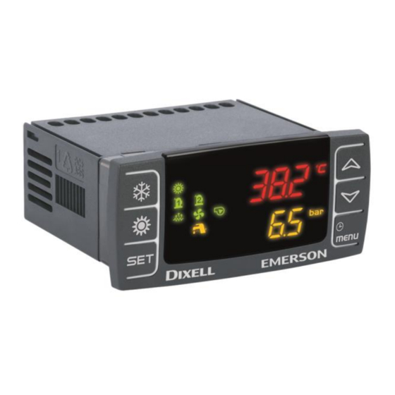
Page 8: User Interface
Alarm: blinking in case of alarm Lighted when sanitary hot water function is active Lighted after pressing menu button Lighted if anti freeze heaters/ integration heating / boiler are activated 1592022010 Quick reference guide iCHILL 100CX EVO rel. 1.0 8/40... -
Page 9: Display Layout
Pressing Up or Down button the display shows the temperature or pressure of the main probes configured in the instrument. The lower display shows the label of the selected probe while the upper display shows its value. 1592022010 Quick reference guide iCHILL 100CX EVO rel. 1.0 9/40... -
Page 10: Other Display Information
In chiller or heat pump if the Energy saving or the Push once again Dynamic setpoint are enabled it shows the real setpoint Setr. Push for 3 seconds Allows to modify the set point 1592022010 Quick reference guide iCHILL 100CX EVO rel. 1.0 10/40... -
Page 11: Key Combinantion
Manual defrost mode Only in Pr3 programming level: In Pr3 defines if the parameter can be modified or push SET and then the MENU key not in the other levels. 1592022010 Quick reference guide iCHILL 100CX EVO rel. 1.0 11/40... -
Page 12: First Installing
HOW TO COPY THE PARAMETER MAP INTO THE “HOT KEY” (UPLOAD) • Power on the instrument • Insert the hot key • Enter the function Menu 1592022010 Quick reference guide iCHILL 100CX EVO rel. 1.0 12/40... -
Page 13: Programming Using Local User Interface
Push SET + DOWN keys together for 3 seconds. The top display shows “PAS” and the bottom display shows “Pr1” Push UP key for 2 seconds and the top display will show Pr2 Push SET key and the top display shows “0” blinking 1592022010 Quick reference guide iCHILL 100CX EVO rel. 1.0 13/40... -
Page 14: Enter Parameters Programming Level Pr3
• CrEn Enable – disable one or the two circuits • COEn Enable – disable one of the compressors • Hour Read and reset the number of compressor running hour 1592022010 Quick reference guide iCHILL 100CX EVO rel. 1.0 14/40... -
Page 15: Alarm List: Read And Reset
If the password is OK the label ArST blinks for 5 seconds then the display returns to normal condition read-out If the password is not correct the display shows PAS again 1592022010 Quick reference guide iCHILL 100CX EVO rel. 1.0 15/40... -
Page 16: Remote Keyboard Vi613
The standard password to reset the alarm log is “4”. REMOTE KEYBOARD VI613 The display visualization and the button functions are the same of the Ichill, then refer to previous chapters of the quick reference guide. 1592022010 Quick reference guide iCHILL 100CX EVO rel. 1.0 16/40... -
Page 17: Remote Lcd Panel Vgi810 Or V2I810
Two models of remote LCD panel are available; VGI810 Visograph 1st series V2I810 Visograph IInd seres The description of the user interface is available in the user manual of the Visograph. 1592022010 Quick reference guide iCHILL 100CX EVO rel. 1.0 17/40... -
Page 18: Remote Touch Panel Vtic10
AC16 Condenser ACFL OFF (3) flow alarm Eeprom alarm AEFL Evaporator OFF (3) flow alarm (boiler) High inlet evaporator (boiler) AEht water temperature Domestic hot AHFL water flow switch alarm 1592022010 Quick reference guide iCHILL 100CX EVO rel. 1.0 18/40... - Page 19 Evaporator 1 AtE1 water pump (boiler) overload alarm Evaporator 2 AtE2 water pump (boiler) overload alarm Domestic hot AtHS water heaters overload supply AtSF overload alarm 1592022010 Quick reference guide iCHILL 100CX EVO rel. 1.0 19/40...
- Page 20 (8) This loads are not influenced directly by the alarm; their status depends on the configuration of the device (9) If A050=0 it is only a warning and the loads are not involved, if A050=1 it is a real alarm and the loads are switched OFF 1592022010 Quick reference guide iCHILL 100CX EVO rel. 1.0 20/40...
-
Page 21: Circuit Alarm
C(n)HP Compressor(n) high pressure switch Compressor(n) oil pressure switch / Oil level C(n)oP switch C1Pd Compressor oil differential C(n)tr Compressor(n) overload if is enabled by parameter the switching OFF of all compressors 1592022010 Quick reference guide iCHILL 100CX EVO rel. 1.0 21/40... -
Page 22: Warning
All the timers are reloaded The alarm, if actives in manual mode at the power down, is not reset 1592022010 Quick reference guide iCHILL 100CX EVO rel. 1.0 22/40... -
Page 23: Wiring Connections
• 1 TTL output to connect: • Hot key 64 for parameters programming • XJ485CX (interface to convert TTL signal to RS485 signal) for monitoring systems (XWEB or third-party system) 1592022010 Quick reference guide iCHILL 100CX EVO rel. 1.0 23/40... -
Page 24: Ic108Cx: Hardware Resources
• 1 TTL output to connect: • Hot key 64 for parameters programming • XJ485CX (interface to convert TTL signal to RS485 signal) for monitoring systems (XWEB or third-party system) 1592022010 Quick reference guide iCHILL 100CX EVO rel. 1.0 24/40... -
Page 25: Remote Panel Connection (Vi613 Evo Or V2I810 Or Vtic10)
"noL" (no link). When using two keyboards VI613 you must configure the dip switch on the rear of the same, giving the first keypad address 1 and 2 to the second keypad. 1592022010 Quick reference guide iCHILL 100CX EVO rel. 1.0 25/40... - Page 26 VI613 LED panel VGI810 or V2I810 LCD PANEL 1592022010 Quick reference guide iCHILL 100CX EVO rel. 1.0 26/40...
-
Page 27: Analog Inputs Ntc - Ptc Probes
VTIC10 TOUCH PANEL NTC – PTC P 17.2 NALOG NPUTS ROBES PbC = common terminal Pb1…Pb6 = probe inputs 1592022010 Quick reference guide iCHILL 100CX EVO rel. 1.0 27/40... -
Page 28: Digital Inputs
17.3 IGITAL NPUTS GND = common terminal ID1…ID11 = digital inputs 1592022010 Quick reference guide iCHILL 100CX EVO rel. 1.0 28/40... -
Page 29: Analog Input For Pressure Transducer Pp30 (4 ÷ 20Ma Signal)
30 (0 NALOG NPUT FOR RESSURE ATIOMETRIC RANSDUCER ÷ 5V SIGNAL +5V = power supply for pressure transducers GND = ground for pressure transducers Pb3 and Pb4 = pressure transducer inputs 1592022010 Quick reference guide iCHILL 100CX EVO rel. 1.0 29/40... -
Page 30: Pwm Output For Condensing Fan Speed Control
OUT3 and OUT4 = signals for the modulation of the condenser fan GND = ground for pressure transducers The compatible modules are the following: XV05PK mono-phase 500 Watt (2A) XV10PK mono-phase 1000 Watt (4A) XV22PK mono-phase 2200 Watt (9A) 1592022010 Quick reference guide iCHILL 100CX EVO rel. 1.0 30/40... -
Page 31: Proportional Output For Fan Condensing Control Or For Compressor Inverter Controlled Or For Auxiliary Outputs
17.7 ROPORTIONAL UTPUT ONDENSING ONTROL OR OMPRESSOR NVERTER ONTROLLED OR UXILIARY UTPUTS OUT1…OUT4 = signals for the modulation of the condenser fan GND = ground for pressure transducers 1592022010 Quick reference guide iCHILL 100CX EVO rel. 1.0 31/40... -
Page 32: Proportional Output 0
If the dumper motor has a common line between a pole of the power supply and the “–“ pole of the 0..10V signal, it is necessary to use two transformers for the power supply of the controller Ichill and the power supply of the dumper motor. 1592022010 Quick reference guide iCHILL 100CX EVO rel. 1.0 32/40... - Page 33 1592022010 Quick reference guide iCHILL 100CX EVO rel. 1.0 33/40...
-
Page 34: Proportional Outputs Configured For Aux Relay Control
17.9 ROPORTIONAL OUTPUTS CONFIGURED FOR AUX RELAY CONTROL OUT1…OUT4 = signals for relays GND = ground 1592022010 Quick reference guide iCHILL 100CX EVO rel. 1.0 34/40... -
Page 35: Connection To The Electronic Expansion Valve Driver Iev22D Or Iev12D
IEV22D ONNECTION LECTRONIC XPANSION ALVE RIVER 17.10 IEV12D The Ichill 100CX EVO can be connected to an Eletctronic expansion valve driver IEV22D or IEV12D through LAN connection. 1592022010 Quick reference guide iCHILL 100CX EVO rel. 1.0 35/40... -
Page 36: Installing And Mounting
VERTICAL BOARDS VI613 PANEL CUT-OUT The keyboard must be mounted on vertical panel with cut-out 72x56 mm, and screwed with two screws. The IP65 can be reached with the gasket RGW-V (optional). 1592022010 Quick reference guide iCHILL 100CX EVO rel. 1.0 36/40... -
Page 37: Electrical Connections
Keep low voltage cables, such as analogue/digital inputs/outputs and probes, away from power cables. • Respect the minimum load current of each relay output, in case of power loads use filtered contactors. 1592022010 Quick reference guide iCHILL 100CX EVO rel. 1.0 37/40... -
Page 38: Technical Data
IGITAL INPUT Type: (configurable software Free contact not opto-insulated parameter) Number of inputs: Notes: Don’t supply voltage to the digital inputs in order to not cause damage to the instrument 1592022010 Quick reference guide iCHILL 100CX EVO rel. 1.0 38/40... -
Page 39: Analogue Outputs
(commercial documentation is not a reference for theese information). To protect the relay contacts of the device, verify the need to use electrical disturbance suppressors or excess voltage protections 1592022010 Quick reference guide iCHILL 100CX EVO rel. 1.0 39/40... -
Page 40: Characteristic Plastic Housing
Thermoplastic PC-ABS Selfhestinguish: V0 (UL94) IP protection: IP65 20.7 OPERATING AND STORAGE TEMPERATURE Operating temperature: -10°C ÷ 55°C Storege temperature: -30°C ÷ 85°C Operating humidity: 20% ÷ 85% (not condensing) 1592022010 Quick reference guide iCHILL 100CX EVO rel. 1.0 40/40...
Need help?
Do you have a question about the iCHILL 100CX EVO and is the answer not in the manual?
Questions and answers