Table of Contents
Advertisement
Advertisement
Table of Contents

Related Manuals for Omron V430-F-series

Summary of Contents for Omron V430-F-series
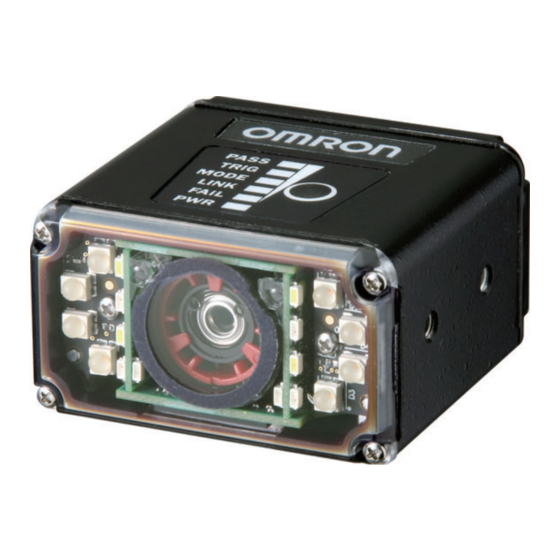
- Page 1 Auto Focus Multi Code Reader V430-F-series User’s Manual Z392-E1-02...
- Page 2 Every precaution has been taken in the preparation of this manual. Nevertheless, OMRON assumes no responsibility for errors or omis sions. Neither is any liability assumed for damages resulting from the use of the information contained in this publication.
-
Page 3: Table Of Contents
CONTENTS CONTENTS Terms and Conditions Agreement ................8 Safety Precautions ....................10 Precautions for Safe Use ..................12 Precautions for Correct Use.................. 14 Regulations and Standards ................... 16 Revision History ..................... 17 Section 1 Quick Start V430-series and WebLink Quick Start ..................1-2 Step 1 —Check Hardware and Connect the System................ - Page 4 CONTENTS Communications by ESP ....................... 3-2 Communications Serial Commands ..................... 3-3 Host Port Connections........................3-4 Host Port Protocol .......................... 3-5 ACK/NAK Options........................... 3-6 Polling Mode Options........................3-7 Ethernet ............................3-8 Response Timeout........................3-13 LRC (Longitudinal Redundancy Check) Status ................. 3-14 Protocol Configuration Examples....................
- Page 5 CONTENTS Section 6 Symbologies Symbologies by ESP ........................6-2 Symbologies Serial Commands ....................6-3 Data Matrix............................6-4 Aztec ..............................6-6 QR Code ............................6-7 Micro QR Code..........................6-8 Code 39............................6-9 Code 128/EAN 128 ........................6-12 BC412............................. 6-15 Interleaved 2 of 5 .......................... 6-16 Code 93............................
- Page 6 CONTENTS Trend Analysis Output 2 ......................7-51 ISO/IEC 16022 Symbol Quality Output 2..................7-51 ISO/IEC 15415 Symbol Quality Output 2..................7-52 ISO/IEC 15416 Symbol Quality Output 2..................7-52 ISO/IEC 29158 Symbol Quality Output 2..................7-52 Diagnostics Output 2........................7-53 Configurable Output 3........................7-53 Trend Analysis Output 3 ......................
- Page 7 CONTENTS Matchcode Type ..........................9-5 Sequence Step Interval ........................ 9-10 Match Replace..........................9-11 Mismatch Replace ........................9-12 New Master Pin ..........................9-13 Section 10 Camera and IP Setup Camera and IP Setup by ESP ...................... 10-2 Camera and IP Setup Serial Commands ..................10-3 Video ..............................
- Page 8 CONTENTS Send ............................... 12-4 Macros ............................12-5 Terminal Menus..........................12-6 Section 13 Utilities Operational Commands ....................... 13-2 Read Rate ............................13-4 Counters ............................13-6 Device Control ..........................13-8 Differences from Default ......................13-9 Master Database ......................... 13-10 Firmware............................13-16 Default/Reset/Save ........................13-19 Reader Status Requests......................
- Page 9 CONTENTS Auto Focus Multi Code Reader V430-series User’s Manual (Z392)
-
Page 10: Terms And Conditions Agreement
Omron’s exclusive warranty is that the Products will be free from defects in materials and workman- ship for a period of twelve months from the date of sale by Omron (or such other period expressed in writing by Omron). Omron disclaims all other warranties, express or implied. - Page 11 Disclaimers Performance Data Data presented in Omron Company websites, catalogs and other materials is provided as a guide for the user in determining suitability and does not constitute a warranty. It may represent the result of Omron’s test conditions, and the user must correlate it to actual application requirements. Actual performance is subject to the Omron’s Warranty and Limitations of Liability.
-
Page 12: Safety Precautions
Safety Precautions Safety Precautions Symbols and the meanings for safety precautions described in this manual. In order for the product to be used safely, the following indications are used in this book to draw your attention to the cautions. The cautions with the indications describe the important contents for safety. - Page 13 Safety Precautions Alert statements in this Manual WARNING This product must be used according to this manual or Instruction sheet. Failure to observe this may result in impairment of functions and performance of the product. This product is not designed or rated for ensuring safety of persons. Do not use it for such purposes. Never connect the AC power supply with this product.
-
Page 14: Precautions For Safe Use
(d) Applications under conditions and environment not described in specifications *1. In addition to the applications listed from (a) to (d) above, Omron products (see definition) are not intended for use in vehicles designed human transport (including two wheel vehicles). Please do NOT use Omron prod- ucts for vehicles designed human transport. - Page 15 • Is not the load of the output signal short-circuited? • Is the load current of the output signal appropriate? • Is not the mistake found in wiring? • The recommended power supply is the S8VS- 24 (manufactured by OMRON) or S8VK-G- 24 (manufactured by OMRON). Ground •...
-
Page 16: Precautions For Correct Use
Precautions for Correct Use Precautions for Correct Use Installation and Storage Sites Install and store the product in a location that meets the following conditions: • Surrounding temperature of 0 to +40°C (-50 to +75°C in storage) • No rapid changes in temperature (place where dew does not form) •... - Page 17 Precautions for Correct Use Component Installation and Handling • Turning OFF the Power When a message is displayed indicating that a task is in progress, do not turn OFF the power. Doing so causes the data in the memory to be corrupted, resulting in the product not operating properly upon the next start-up.
-
Page 18: Regulations And Standards
EN61326-1 Electromagnetic environment: Industrial electromagnetic environment (EN/IEC 61326-1 Table 2) • This product complies with EC/EU Directives. EMC-related performance of the OMRON devices that comply with EC/EU Directives will vary depending on the configuration, wiring, and other conditions of the equipment or control panel on which the OMRON devices are installed. -
Page 19: Revision History
Revision History Revision History A manual revision code appears as a suffix to the catalog number on the front and back covers of the manual. Cat. No. Z392-E1-02 Revision code Revision code Date Revised content March 2018 Original production April 2018 Corrected mistakes Auto Focus Multi Code Reader V430-series User’s Manual (Z392) -
Page 20: Quick Start
1 Quick Start Contents V430-series and WebLink Quick Start ..................1-2 Step 1 —Check Hardware and Connect the System..............1-2 Step 2 —Mount and Position the Reader ..................1-4 Step 3 —Connect to WebLink....................... 1-4 Step 4 —Explore the Start View ....................1-5 Step 5 —Create a New Setup or Load an Existing Setup ............ -
Page 21: V430-Series And Weblink Quick Start
Check Hardware and Connect the System V430-series and WebLink Quick Start Step 1 — Check Hardware and Connect the System Item Description Model Number V430-F V430-F Power Supply, 100-240VAC, +24VDC, M12 12-Pin Socket V430-W8-3M Cordset, Host, Ethernet, M12 8-Pin Plug (Screw-On) to RJ45, 3 m. V430-WE-3M To Power To Host... -
Page 22: Step 2 -Mount And Position The Reader
Quick Start Step 2 — Mount and Position the Reader • Position the reader several inches from the symbol. You may need to reposition the reader a few times to find the ideal distance. • Tip the reader relative to the symbol to avoid the glare of direct (specular) reflection. •... -
Page 23: Step 3 -Connect To Weblink
Connect to WebLink Step 3 — Connect to WebLink Type http://192.168.188.2 (the default IP address) in the web browser’s address bar. The WebLink session will begin shortly after you enter the reader’s IP address. V430-series (Static Connection) 1. Navigate to Control Panel > Network and Sharing Center on your PC. 2. -
Page 24: Step 4 -Explore The Start View
Quick Start Step 4 — Explore the Start View The Start view is the initial view you will see when the session begins. The connected reader is shown, along with its user-defined name (19 characters or fewer), IP address, Reader Model, Serial Number, MAC ID, Firmware Version, Sensor, Optics, Decoder, and Speed. -
Page 25: Step 5 -Create A New Setup Or Load An Existing Setup
Create a New Setup or Load an Existing Setup Step 5 — Create a New Setup or Load an Existing Setup Assisted Setup When you click the Assisted Setup button in the Start view, a dialog will appear asking you a series of application-based questions. Based on your answers, WebLink generates your initial setup automatically. -
Page 26: Step 6 -Explore The Setup View
Quick Start Step 6 — Explore the Setup View The Setup view allows you to configure all aspects of a setup. Multiple discrete sections of the interface give you the ability to set Cycle, Acquire, Decode, Match String, Format Output, Output parameters, and Favorites. Clicking the Save icon at the upper right saves current settings to the reader’s flash memory so the settings will be available when the reader is rebooted. -
Page 27: Step 7 -Configure Read Cycle Settings
Configure Read Cycle Settings Step 7 — Configure Read Cycle Settings The Cycle section of the Setup view allows you to modify the trigger, determine the number of symbols for the reader to expect, and set Read Cycle Timeout. A dropdown menu of various Cycle types provides a variety of options, each with configurable parameters. - Page 28 Quick Start Start / Stop This mode uses External Level with a Read Cycle Timeout and Continuous Capture, allowing you to set Leading Edge and Trailing Edge as well as the Serial Trigger and the Start and Stop characters. Serial Trigger (Non-Delimited) Off When Serial Trigger is set to Off, the start and stop characters are set to NULL, meaning that the trigger is disabled.
-
Page 29: Step 8 -Configure Acquire Settings
Configure Acquire Settings Step 8 — Configure Acquire Settings Acquire settings allow you to set Exposure (signified by the sun icon) and Gain (signified by the dial and right-pointing arrow icon) in real time. Clicking any of these settings will cause a control to appear, allowing you to modify that setting. - Page 30 Quick Start Spot Focus If the camera is in Continuous mode or Continuous Auto (Continuous mode with Auto Photometry enabled), you can perform a localized quick focus in the image. If you click the focus button, the Autofocus and Spot Focus icons appear: When you click the Spot Focus icon, the Select a location in the image to autofocus message appears: The cursor transforms into crosshairs as shown in the example below.
- Page 31 Configure Acquire Settings Enhance The Enhance dropdown menu at the bottom of the Acquire settings editor allows you to select the method for processing captured images. Grow Dark Grow Dark increases the dark cell size of a symbol. It is useful for increasing the dark cell size of a dark-on-light Data Matrix symbol.
-
Page 32: Step 9 -Configure Symbology Settings
Quick Start Step 9 — Configure Symbology Settings Clicking the gear icon at the bottom of the Decode dialog brings up Symbology Settings. This allows you to configure every parameter for every available code type. Data Matrix error correction parameters are shown in this example, but you can configure any parameter for any of the code types supported by WebLink. -
Page 33: Step 10 -Format Output And Configure Match String
Format Output and Configure Match String Step 10 — Format Output and Configure Match String Format Output, when enabled in the Setup view, allows you to determine the many ways in which barcode data can be formatted and parsed before it is output as a data string. You can also set Preamble and Postamble in this dialog. -
Page 34: Step 11 -Configure Output 1, 2, And 3 Settings
Quick Start Step 11 — Configure Output 1, 2, and 3 Settings Bring up the Output 1, Output 2, and Output 3 dialogs by clicking on the Outputs section at the lower left of the Setup view. For each output you can determine the Output On behavior, Mode, Pulse Width, and State. -
Page 35: Step 12 -Run The Application
Run the Application Step 12 — Run the Application In the Run view, you can observe the progress of the setup as it follows the parameters you have defined. The right panel of the UI shows Counts for Cycles, Reads, No Reads, and Mismatches, as well as Rate information for Capture, Decode, Overhead, Total Read, and Trigger Rate, as well as Output Data. -
Page 36: V430-Series And Esp Software Quick Start
Quick Start V430-series and ESP Software Quick Start Step 1 — Check Hardware and Connect the System Item Description Model Number V430-F V430-F Power Supply, 100-240VAC, +24VDC, M12 12-Pin Socket V430-W8-3M Cordset, Host, Ethernet, M12 8-Pin Plug (Screw-On) to RJ45, 3 m. V430-WE-3M To Power To Host... -
Page 37: Step 2 -Mount And Position The Reader
Mount and Position the Reader Step 2 — Mount and Position the Reader • Position the reader several inches from the symbol. You may need to reposition the reader a few times to find the ideal distance. • Tip the reader relative to the symbol to avoid the glare of direct (specular) reflection. •... -
Page 38: Step 3 -Install Esp
Quick Start Step 3 — Install ESP ESP Software can be found on Microscan’s Tools Drive that is packaged with the reader if the Drive was ordered at the time of purchase. ESP can also be installed from the Download Center, located at: www.microscan.com. -
Page 39: Step 4 -Select Model
Select Model Step 4 — Select Model When you start ESP, the following menu will appear: 1. Click the button showing your model of the reader. 2. Click OK or double-click one of the buttons to select your reader. 3. Depending on the model you have selected, you will see the appropriate Would you like to connect to the [XX] dialog after selecting your reader and clicking OK. - Page 40 Quick Start Note: If you connect to the V430-F, you need to select the "MicroHAWK ID-40" once. Click No when asked if you would like to connect the MicroHAWK ID-40. Click Connect on the menu toolbar, and then select Connection Wizard, Click Con- nect when you see the dialog.
-
Page 41: Step 5 -Connect
Connect Step 5 — Connect • Click Connect on the menu toolbar, and then select Connection Wizard. • Select the communication interface required by your application. • Configure settings as required by the application, and click Connect. • When a connection is established, the green indicator in the status bar at the bottom right of the screen will be visible: Important: For best connection results, be sure that no decodable symbols are within the reader’s field of view while attempting to connect. -
Page 42: Step 6 -Locate The Symbol In The Field Of View
Quick Start Step 6 — Locate the Symbol in the Field of View • In ESP’s EZ Mode, click the Locate button to enable the blue target pattern. The symbol in the field of view will appear in the video view beneath the Locate and Calibrate buttons, and you will see the blue target pattern projected from the front of the reader. -
Page 43: Step 7 -Calibrate
Calibrate Step 7 — Calibrate V430-series settings can be adjusted automatically in ESP for optimum symbol decod- ing performance. During the calibration routine, the reader will flash its amber Read Rate percent LEDs and red illumination LEDs while searching camera settings and determining the best configuration for decoding symbol data. -
Page 44: Step 8 -Test Read Rate
Quick Start Step 8 — Test Read Rate Read Rate indicates the number of successful decodes per second achieved by the reader. Test Read Rate by ESP 1. Click the Test button to start the Read Rate test and Stop to end it. If a symbol has been successfully decoded, the symbol’s data and related features will be presented in the field below the image display window. -
Page 45: Step 9 -Configure The Reader In Esp
MicroHAWK ID Part Numbers Step 9 — Configure the Reader in ESP Click the App Mode button to make configuration changes to the V430-series reader. The following modes are accessible by clicking the buttons in the first row of App Mode icons: •... -
Page 46: Step 10 -Save Configuration In Esp
Quick Start Step 10 — Save Configuration in ESP To make changes to a configuration setting: 1. Left-click on the to expand the desired tree. 3. Place your cursor in the 2. Double-click on the selection box, scroll down to desired parameter the setting you want to and click once in the... -
Page 47: How To Read Model Numbers
Save Configuration in ESP How to Read Model Numbers V430-F000W 12M Auto Focus Multi Code Reader V430-F series Focal Distance (WD) 000: Auto Focus 050: 50 mm 081: 81 mm 102: 102 mm Optics W: Standard Density, Wide View M: High Density, Middle View N: Ultrahigh Density, Narrow View Effective pixels 50: 5.0 Megapixel, QSXGA 2592 x 1944... -
Page 48: Using Esp
2 Using ESP Contents EZ Mode............................2-2 App Mode............................2-3 Menu Toolbar ..........................2-4 View ............................2-13 Navigating in ESP ........................2-14 Send/Receive Options ........................2-15 This section is designed to help you understand the basic structure and elements of ESP (Easy Setup Program). When you open ESP, unless otherwise specified in the ESP Preferences dialog accessible from the Options heading on the menu toolbar, you will enter EZ Mode for initial setup. -
Page 49: Ez Mode
EZ Mode EZ Mode In EZ Mode you are presented with the Locate, Calibrate, and Test options. After connecting to your reader, EZ Mode is the screen you will see. You will be provided with on-screen instructions that will help you with positioning, testing, and calibration. Test Click the Test button to start the Read Rate test for a quick indication of the reader’s read capabilities and the limits of your application. -
Page 50: App Mode
Using ESP App Mode From EZ Mode, you can click on the App Mode button to access specific configuration menus, Utilities tools, Camera setup, Output Format options, and a Terminal window where serial commands can be entered. Note: The App Mode and EZ Mode buttons appear in the same position to allow easy switching between these primary modes. -
Page 51: Menu Toolbar
Menu Toolbar Menu Toolbar File > New Whenever New is selected, the default configuration of ESP is loaded. Open/Save When Save or Save As is selected, the ESP configuration is saved to the host computer’s hard drive and available whenever the same file is selected under Open. - Page 52 Using ESP Model In the Model menu you can select any of the models supported by ESP. When you choose a different model, the connection to your present model will be terminated. To connect to another model, select New Model, choose a new model from the pop-up menu that appears, and click OK.
- Page 53 Menu Toolbar Options The Options menu allows you to save memos and set up ESP Preferences. Note: Preferences will be saved and loaded into ESP whenever ESP is opened next, whether or not you save the ESP file. Preferences > General Tab The Toolbar Style options allow you to determine how ESP...
- Page 54 Using ESP Preferences > Terminal Tab Show Non-Printable Characters When Show Non-Printable Characters is enabled, characters such as “CRLF” will be displayed in the Terminal window. When Enhanced Format is checked, the characters are displayed with more detailed formatting. Change Keyboard Macros Clicking the Change Keyboard Macros button brings up the Function Keys dialog.
- Page 55 Menu Toolbar Preferences > Bar Code Options Tab The Bar Code Options dialog allows you to set the size of user-created symbols. Sizing Information Sets the bar width or module width (in mils, or thousandths of an inch) of user-created symbols. Example: A bar width of 18 is 0.018 inches.
- Page 56 Using ESP Preferences > Advanced Tab The Auto Sync options at the top of the Advanced tab allow you to determine whether Auto Sync will be enabled automatically in sections of ESP where it is used, or if it will ask you before it enables Auto Sync functions.
- Page 57 Menu Toolbar Preferences > Advanced Tab (cont.) Ask to Save ESP File when Quitting When enabled, prompts the user to save a .esp file when ending a session. The .esp file will be saved in the location of your choice. Connect to Readers via TCP/IP When enabled, shows a TCP/IP option on the Connection Wizard.
- Page 58 Using ESP Document Memo The information you type in the Document Memo field will appear in a context-sensitive text box whenever your cursor hovers over the Document Memo item on the Options menu. Model Memo Similar to Document Memo, the information you type in the Model Memo field will appear in a context-sensitive text box whenever your cursor hovers over the Model Memo item on the Options menu.
- Page 59 Menu Toolbar Connect The Connect dropdown menu allows the user to access the Connection Wizard, as well as the Autoconnect dialog. Connect and Disconnect can also be performed directly from the dropdown menu without opening a dialog. Connection Wizard To connect using the Connection Wizard: •...
-
Page 60: View
Using ESP View The View menu allows you to move quickly between Parameters, Setup, Terminal, and Utilities without using the icon buttons on the App Mode toolbar. It also allows you to access the Bar Code Dialog. Bar Code Dialog In the Bar Code Dialog you can create symbols by typing the text you wish to encode. -
Page 61: Navigating In Esp
Navigating in ESP Navigating in ESP Click the App Mode button to change reader settings, or to access the Utilities, Camera, Terminal, or Output Format views. To return to EZ Mode, click the EZ Mode button. To make changes to configuration settings in the tree controls: 1. -
Page 62: Send/Receive Options
Using ESP Send/Receive Options To access Receive, Save, and Default options, click the Send/Recv button. You can also access these options by right-clicking in any of the configuration views. Receiving From the Send/Recv menu, select Receive Reader Settings. Caution: Do not select this option if you do not want to upload the reader’s settings. For example, if your ESP file has a number of custom settings that you want to maintain and download into the reader, these settings would be lost by choosing Yes. - Page 63 Send/Receive Options Defaulting When you select Default Current Menu Settings or Default all ESP Settings, you are only defaulting the ESP settings. Advanced Options Send Current View This is the same as Save to Reader > Send No Save except that only the commands in the current configuration tree are sent.
- Page 64 3 Communications Contents Communications by ESP ......................3-2 Communications Serial Commands....................3-3 Host Port Connections ........................3-4 Host Port Protocol......................... 3-5 ACK/NAK Options......................... 3-6 Polling Mode Options........................3-7 Ethernet ............................3-8 Response Timeout........................3-13 LRC (Longitudinal Redundancy Check) Status ................3-14 Protocol Configuration Examples....................
-
Page 65: Communications By Esp
Communications by ESP Communications by ESP Click the Parameters button and then the Communication tab. To open nested options, To change a setting, double-click the single-click the +. setting and use your cursor to scroll through the options. Auto Focus Multi Code Reader V430-series User’s Manual (Z392) -
Page 66: Communications Serial Commands
Communications Communications Serial Commands Host Port Connections <K100,baud rate,parity,stop bits,data bits> Ethernet <K126,status,IP address,subnet,gateway,IP address mode> Ethernet TCP Ports <K127,TCP Port 1,TCP Port 2> Search and Configure Mode <K128,status,timed window> EtherNet/IP <K129,status> Host Protocol <K140,protocol,address> Preamble <K141,status,preamble characters> Postamble <K142,status,postamble characters> Response Timeout <K143,response timeout>... -
Page 67: Host Port Connections
Host Port Connections Host Port Connections The host port can be configured with RS-232 connections. The following settings define the basic transmission speeds and digital standards that ensure common formatting. Baud Rate, Host Port Usage: Can be used to transfer data faster or to match host port settings. Definition: The rate at which the reader and host transfer data back and forth. -
Page 68: Host Port Protocol
Communications Host Port Protocol Usage: In general, the point-to-point protocols will work well in most applications. They require no address and must use RS-232 communications standards. Definition: Protocols define the sequence and format in which information is transferred between the reader and the host. Serial Cmd: <K140,protocol,address>... -
Page 69: Ack/Nak Options
ACK/NAK Options ACK/NAK Options Definition: These parameters take effect for ACK/NAK <K140,4> on the main RS-232 port and are completely independent of the Polling Mode Options <K148>. The reader always follows the protocol in both directions (to and from the host). -
Page 70: Polling Mode Options
Communications Polling Mode Options Definition: These parameters only take effect for Polling Mode <K140,5> on the main RS-232 port and are completely independent of the ACK/NAK Options <K147>. The values of protocol characters can be changed, but the protocol events cannot be disabled. -
Page 71: Ethernet
Ethernet Ethernet Enables or disables Ethernet connectivity in the reader. This corresponds to the <K126> command. It requires a <Zrdall> to return to default settings. IP Address This is the IP address of the reader when it is in Static IP Address Mode. Auto Focus Multi Code Reader V430-series User’s Manual (Z392) - Page 72 Communications Subnet This is the subnet of the reader when it is in Static IP Address Mode. Gateway This is the gateway IP address of the reader when it is in Static IP Address Mode. Auto Focus Multi Code Reader V430-series User’s Manual (Z392)
- Page 73 Ethernet IP Address Mode Determines how the reader’s IP address will be defined. Static In Static Mode, the reader uses the user-defined IP address. This is the default state for V430-series. DHCP In DHCP Mode, the reader automatically acquires the IP address, Subnet, and Gateway addresses from a DHCP or BOOTP server.
- Page 74 Communications TCP Port 1 One of two TCP ports for Ethernet communication with the reader. The default setting is 2001. TCP Port 2 One of two TCP ports for Ethernet communication with the reader. The default setting is 2003. 3-11 Auto Focus Multi Code Reader V430-series User’s Manual (Z392)
- Page 75 Ethernet Search and Configure Mode Note: Search is the non-applicable function in V430-F. Please use DDU (Device Discovery Utility) software, when using V430-F. Search and Configure Mode is intended primarily for initial setup of an reader in a network. This parameter controls whether or not the reader will respond to ESP’s Search function in the Ethernet TCP/IP connect dialog section of the Connection Wizard: After the reader is in full use in an application, you may want the...
-
Page 76: Response Timeout
Communications Response Timeout Usage: Only used when a response is required from the host. The reader can be set to wait indefinitely by setting Response Timeout to zero. Definition: The time that the reader will wait before timing out if ACK, NAK, and ETX are enabled, and a host response is expected. -
Page 77: Lrc (Longitudinal Redundancy Check) Status
LRC (Longitudinal Redundancy Check) Status LRC (Longitudinal Redundancy Check) Status Usage: Used when extra data integrity is required. Definition: An error-checking routine that verifies the accuracy of transmissions. It is the exclusive OR of all characters following the STX (start of text) up to and including the ETX (end of text). -
Page 78: Protocol Configuration Examples
Communications Protocol Configuration Examples Point-to-Point (Main Port) <K100,8,0,1,1> Baud Rate: 115.2K; Parity: None; Stop Bits: 2; Data Bits: 8 <K140,0> Point-to-Point <K102,0> RS-232 enabled Polling Mode (Main Port) <K100,4,0,1,1> Baud Rate: 9600; Parity: None; Stop Bits: 2; Data Bits: 8 <K140,5,23>... -
Page 79: Preamble
Preamble Preamble Preamble Status Usage: Useful for identifying and controlling incoming data. For example, defining the preamble as a carriage return and a line feed causes each decoded message to be displayed on its own line. Definition: Defines a one to four character data string that can be added to the front of the decoded data. -
Page 80: Postamble
Communications Postamble Postamble Status Usage: Useful for identifying and controlling incoming data. For example, defining the postamble as a carriage return and a line feed causes each decoded message to be displayed on its own line. Definition: Allows the user to enable or disable up to four postamble characters that can be added to the end of the decoded data. -
Page 81: Ethernet/Ip Byte Swapping Enabled
EtherNet/IP Byte Swapping Enabled EtherNet/IP Byte Swapping Enabled Definition: Enables or disables EtherNet/IP byte swapping for decode data. Serial Cmd: <K163,status> Default: Disabled Options: 0 = Disabled 1 = Enabled 3-18 Auto Focus Multi Code Reader V430-series User’s Manual (Z392) -
Page 82: Profinet
Communications PROFINET Definition: Enables or disables the PROFINET communications protocol. Serial Cmd: <K164,status> Default: Disabled Options: 0 = Disabled 1 = Enabled 3-19 Auto Focus Multi Code Reader V430-series User’s Manual (Z392) -
Page 83: Entering Ascii Characters As Hex Values
Entering ASCII Characters as Hex Values Entering ASCII Characters as Hex Values Commands that require ASCII text fields, such as Preamble and Postamble commands, can be sent to the reader as hex values. Serial Cmd Format: <Knnnh,00-FF> To enter ASCII fields as hex values (00 to FF), add a lower-case h directly after the command’s K number, and then enter the hex value that corresponds with the desired ASCII character. -
Page 84: Calibration
4 Calibration Contents Calibration Serial Commands ....................... 4-2 Calibration Overview........................4-2 Calibration Options ........................4-3 Calibration by ESP........................4-10 Initiating Calibration ........................4-12 Additional Notes about Calibration....................4-13 This section shows the calibration options, and explains the different ways that those options can be configured. -
Page 85: Calibration Serial Commands
Calibration Serial Commands Calibration Serial Commands <K529,gain,exposure,focus position,symbol type,WOI framing, Calibration Options WOI margin, line scan height,processing> Calibration Overview Calibration is one of the most powerful features of the V430-series. The calibration pro- cess can be initiated by serial command or in the ESP user interface. When the reader enters calibration, it runs through an optimization cycle that sets the ideal parameters for reading symbols at the highest possible level of performance. -
Page 86: Calibration Options
Calibration Calibration Options This command specifies the operation of the calibration feature. The default configuration performs calibration on gain and symbol type. The calibration process optimizes the gain setting for the configured exposure. Gain Definition: When enabled, gain is calibrated to provide the best available image quality and performance. - Page 87 Calibration Options Exposure Definition: Unless the application is static, exposure should be configured based on the application’s line speed. The table below is a general guideline for exposure configurations at various line speeds. Serial Cmd: <K529,gain,exposure,focus position,symbol type,WOI framing,WOI margin, line scan height,processing>...
- Page 88 Calibration Focus Position Definition: The reader’s focus position can be configured by entering the target distance value, so focus position can usually be configured without calibration. However, if it is necessary to calibrate the focus distance there are two methods: the standard Search Method and a Quick Focus method, both of which are defined below.
- Page 89 Calibration Options Symbol Type Serial Cmd: <K529,gain,exposure,focus position,symbol type,WOI framing,WOI margin,line scan height,processing> Default: Enabled Options: 0 = Disabled 1 = Enabled Disabled When this feature is disabled, only the current enabled symbologies will be considered during the calibration process. Enabled When this feature is enabled, autodiscrimination is in effect during the calibration process.
- Page 90 Calibration Window of Interest (WOI) Framing Definition: If WOI Framing is enabled, the camera’s Window of Interest will be set to a full size image when calibration begins. Once a symbol is decoded, the camera WOI will be zoomed in both vertically and horizontally (regardless of which WOI mode is enabled) to include the symbol plus an additional margin.
- Page 91 Calibration Options Straight Line This feature is intended for use with linear symbologies. If the calibration process is successful, the orientation of the symbol is determined and the Window of Interest is modified according to the symbol orientation. The scan line orientation is determined to be vertical if the symbol tilt is between 225°...
- Page 92 Calibration Window of Interest (WOI) Margin Definition: Sets the margin size that is applied to the calibrated symbol. This parameter is expressed in number of pixels. If the margin causes the image to exceed the maximum image size, it will be reduced accordingly. Serial Cmd: <K529,gain,exposure,focus position,symbol type,WOI framing,WOI margin, line scan height,processing>...
-
Page 93: Calibration By Esp
Calibration by ESP Calibration by ESP ESP’s Calibration view incorporates all the functionality of the <K529> (Calibration Options) command in a single easy-to-use, intuitive interface. This calibration process allows the user much finer control of individual parameters than the calibration routine in EZ Mode or on the Video tab. - Page 94 Calibration After Calibration The Shutter, Gain, and Quality indicator bars remain stationary at the end of calibration to provide a visual reference for the final values of these parameters. The calibration progress bar indicates that the process has been completed. Notice the improved image resolution after the calibration process is complete.
-
Page 95: Initiating Calibration
Initiating Calibration Initiating Calibration Calibration can be initiated by serial command or from the Calibration interface in ESP. A symbol must be in the reader’s field of view during the calibration process. In ESP, the Calibrate button starts the calibration routine. Note: If you choose to calibrate the reader by sending a <@CAL>... -
Page 96: Additional Notes About Calibration
Calibration Additional Notes about Calibration The following conditions apply to the reader’s calibration process. Some of these items are noted at various points throughout this section, or in other sections of the reader’s documentation. 1. If Window of Interest Framing is enabled, the WOI will be set to full frame when calibration begins. - Page 97 Additional Notes about Calibration 4-14 Auto Focus Multi Code Reader V430-series User’s Manual (Z392)
-
Page 98: Read Cycle
5 Read Cycle Contents Read Cycle by ESP ........................5-2 Read Cycle Serial Commands...................... 5-3 Read Cycle Setup......................... 5-4 Multisymbol........................... 5-5 Trigger Mode and Filter Duration....................5-6 External Trigger Polarity ......................5-11 Serial Trigger ..........................5-12 Start Trigger Character (Non-Delimited)..................5-13 Stop Trigger Character (Non-Delimited) .................. -
Page 99: Read Cycle By Esp
Read Cycle by ESP Read Cycle by ESP Click the Parameters button and then the Read Cycle tab. To change a setting, double-click the To open nested options, setting and use your single-click the +. cursor to scroll through the options. Auto Focus Multi Code Reader V430-series User’s Manual (Z392) -
Page 100: Read Cycle Serial Commands
Read Cycle Read Cycle Serial Commands <K200,trigger mode,leading edge trigger filter,trailing edge Trigger Mode/Filter Duration trigger filter> Serial Trigger Character <K201,serial trigger character> External Trigger State <K202,external trigger state> End of Read Cycle <K220,end of read cycle mode,read cycle timeout> Decodes Before Output <K221,good decode(s) needed>... -
Page 101: Read Cycle Setup
Read Cycle Setup Read Cycle Setup Setting up read cycle and triggering parameters will involve a series of decisions based on your particular application, as follows: 1. Select the number of symbols to be read in a single cycle. The reader can read mul- tiple symbols in a single image frame. -
Page 102: Multisymbol
Read Cycle Multisymbol Usage: Multisymbol is commonly used in shipping applications where a shipping symbol contains individual symbols for part number, quantity, etc. This feature allows on trigger to pick up all the symbols. Definition: Multisymbol allows the user to define up to 100 symbols that can be read in a single read cycle. -
Page 103: Trigger Mode And Filter Duration
Trigger Mode and Filter Duration Trigger Mode and Filter Duration Trigger Mode Definition: The Trigger is the event that initiates a read cycle. Note: When calibrating the reader or testing read rate, the current trigger setting will be disregarded. Serial Cmd: <K200,trigger mode,leading edge trigger filter,trailing edge trigger filter>... - Page 104 Read Cycle Continuous Read 1 Output Usage: Continuous Read 1 Output can be useful in applications where it is not feasible to use a trigger and all succeeding symbols contain different information. It is also effective in applications where the objects are presented by hand.
- Page 105 Trigger Mode and Filter Duration External Level Initiate Read Cycle: Object #1, moving in front of the detector beam, causes a change in the trigger state, which initiates the read cycle. End Read Cycle: The same object, moving out of the detector beam, causes another change in the trigger state, which ends the read cycle.
- Page 106 Read Cycle Serial Data Usage: Serial Data is effective in a highly controlled environment where the host knows precisely when the object is in the field of view. It is also useful in determining if a No-Read has occurred. Definition: In Serial Data, the reader accepts an ASCII character from the host or controlling device as a trigger to start a read cycle.
- Page 107 Trigger Mode and Filter Duration Leading Edge Trigger Filter Usage: Used to ignore spurious triggers when Trigger Mode is set to External Edge or External Level. Definition: To consider a change in state on the trigger input, the level must be stable for the trigger filter duration.
-
Page 108: External Trigger Polarity
Read Cycle External Trigger Polarity Usage: Allows users to select the trigger polarity that will be used in their application. Definition: Determines the active state of the trigger signal applied to the cable input of the reader. Serial Cmd: <K202,active state> Default: Positive Options:... -
Page 109: Serial Trigger
Serial Trigger Serial Trigger Usage: Allows the user to define the trigger character and delimiters that start and stop the read cycle. Definition: A serial trigger is considered an online host command and requires the same command format as all host commands. It must be entered within angle bracket delimiters <... -
Page 110: Start Trigger Character (Non-Delimited)
Read Cycle Start Trigger Character (Non-Delimited) Usage: Useful in applications where different characters are required to start a read cycle. Definition: A single ASCII host serial trigger character that starts the read cycle and is not enclosed by delimiters such as < and >. Non-delimited Start characters can be defined and will function according to the trigger event. -
Page 111: Stop Trigger Character (Non-Delimited)
Stop Trigger Character (Non-Delimited) Stop Trigger Character (Non-Delimited) Usage: Useful in applications where different characters are required to end a read cycle. Definition: A single ASCII host serial trigger character that ends the read cycle and is not enclosed by delimiters such as < and >. Non-delimited Stop characters can be defined and will function according to the trigger event. -
Page 112: End Of Read Cycle
Read Cycle End of Read Cycle Definition: The read cycle is the time during which the reader will attempt to capture and decode a symbol. A read cycle can be ended by a timeout, a new trigger, or by the last frame in a capture sequence or a combination of the above. - Page 113 End of Read Cycle New Trigger Usage: New Trigger is an effective way to end a read cycle when objects move past the reader at irregular intervals (not timing-dependent). Definition: New Trigger ends the current read cycle and initiates a new one when a new trigger occurs.
-
Page 114: Capture Mode
Read Cycle Capture Mode Definition: Capture Mode relates to the way that images are captured and processed. <K241,capture mode,number of captures,rapid capture mode,number of Serial Cmd: continuous captures,images per read cycle limit,read cycle history> Default: Continuous Capture Options: 0 = Rapid Capture 1 = Continuous Capture Rapid Capture Definition:... - Page 115 Capture Mode Number of Captures Usage: Number of Captures is used to specify the number of captures to be processed in Rapid Capture Mode. Definition: Sets the total number of captures that are processed during a read cycle in Rapid Capture Mode. This feature is used in conjunction with Capture Timing parameters to specify the capture sequence of a rapid capture read cycle.
- Page 116 Read Cycle Timed Capture Usage: Timed Rapid Capture is useful in fast-moving applications in which symbols are only in the field of view for a short time and precise timing is required. Definition: In Timed Rapid Capture, decoding occurs independent of and simultaneous with capturing, thus allowing precise timing or no delay at all between captures.
- Page 117 Capture Mode Triggered Capture Usage: Useful in applications where each decode must be treated as a discrete event, regardless of symbol data. Definition: The first trigger event starts the read cycle, and subsequent triggers will continue until the predetermined Number of Captures is met, or until the predetermined End of Read Cycle condition is met-- whichever occurs first.
- Page 118 Read Cycle Number of Continuous Captures Definition: Specifies the number of captures to process in Continuous Capture mode. Serial Cmd: <K241,capture mode,number of captures,rapid capture mode,number of continuous captures,images per read cycle limit,read cycle history> Default: Options: 1 and 255 Images per Read Cycle Limit Definition: Specifies the number of captures to process in a read cycle.
-
Page 119: Capture Timing
Capture Timing Capture Timing Note: Capture Timing applies only to Rapid Capture Mode. Time Before First Capture Usage: In almost any moving line application, a time delay is needed to ensure that a symbol will be in the reader’s field of view at the beginning of the capture sequence. - Page 120 Read Cycle Time Between Captures Usage: This is useful in applications where more than one symbol can appear during a single read cycle (multisymbol), or where line speeds are slow enough that captured frames might overlap or miss a symbol. Definition: A time delay can be inserted between individual frame captures in Rapid Capture Mode.
-
Page 121: Image Processing Timeout
Image Processing Timeout Image Processing Timeout Usage: Useful in higher speed applications where image processing time is long enough that not all captures have an opportunity to be processed. Definition: Specifies the maximum amount of time to process a captured image. When the timeout expires, the image processing is aborted. -
Page 122: Image Storage
Read Cycle Image Storage Image Storage Type Definition: Allows the user to store images from separate read cycles and to retrieve them later. The number of available slots for storage depends on the mode of operation. If the reader is in Rapid Capture Mode, the number of images that can be stored is equivalent to the maximum number of the rapid count (the current rapid count setting). - Page 123 Image Storage Image Storage Example The following example assumes that the reader is in a rapid capture mode of 3 captures. Number of Symbols: Frame # 1: No-Read Frame # 2: No-Read Frame # 3: Good Read, Symbol # 1 Read Cycle Result: Good Read Stored Frame:...
-
Page 124: Decodes Before Output
Read Cycle Decodes Before Output Good Decode(s) Needed Definition: This value specifies the number of times a symbol needs to be read to qualify as a good read. Serial Cmd: <K221,good decode(s) needed> Default: Options: 1 to 255 5-27 Auto Focus Multi Code Reader V430-series User’s Manual (Z392) -
Page 125: Auto Focus Multi Code Reader V430-Series User's Manual (Z392)
Good Decode(s) Needed 5-28 Auto Focus Multi Code Reader V430-series User’s Manual (Z392) - Page 126 6 Symbologies Contents Symbologies by ESP........................6-2 Symbologies Serial Commands ....................6-3 Data Matrix ........................... 6-4 Aztec ............................6-6 QR Code ............................6-7 Micro QR Code..........................6-8 Code 39............................6-9 Code 128/EAN 128 ........................6-12 BC412 ............................6-15 Interleaved 2 of 5........................6-16 Code 93............................
-
Page 127: Symbologies By Esp
Symbologies by ESP Symbologies by ESP Click the Parameters button and then the Symbologies tab. To change a setting, double-click the setting and use your cursor to scroll through the options. To open nested options, single-click the +. Auto Focus Multi Code Reader V430-series User’s Manual (Z392) -
Page 128: Symbologies Serial Commands
Symbologies Symbologies Serial Commands Composite <K453,symbology status,separator status,separator character> Aztec <K458,status> Micro QR Code <K459,status> <K460,postal symbology type,POSTNET status,PLANET Postal Symbologies status,USPS4CB status> <K470,status,check character status,check character output Code 39 status, large intercharacter gap,fixed symbol length status, fixed symbol length,full ASCII set> <K471,status,start/stop match,start/stop output,large intercharacter Codabar gap,fixed symbol length status,symbol length,check character... -
Page 129: Data Matrix
Data Matrix Data Matrix Usage: Very useful where information needs to be packed into a small area, and/or where symbols need to be applied directly to the substrate with laser etching, chemical etching, dot peen, or other methods. Definition: Data Matrix is a type of Matrix symbology and has subsets ECC 000 - ECC 200. ECC 200 symbols have an even number of rows and an even number of columns. - Page 130 Symbologies ECC 080 Definition: When enabled, will decode ECC 080 symbols. Serial Cmd: <K479,ECC 200 status,ECC 000 status,ECC 050 status,ECC 080 status, ECC 100 status,ECC 140 status,ECC 120 status,ECC 130 status> Default: Disabled Options: 0 = Disabled 1 = Enabled ECC 100 Definition: When enabled, will decode ECC 100 symbols.
-
Page 131: Aztec
Aztec Aztec Usage: Used in document imaging, railway ticket validation, and some postal applications. Definition: A 2D matrix symbology built on a square grid with a square “bull’s-eye” pattern at the center. Aztec can encode up to 3,832 numeric or 3,067 alphabetical characters, or 1,914 bytes of data. -
Page 132: Qr Code
Symbologies QR Code Usage: Widely implemented in the automotive industry in Japan and throughout their worldwide supply chain. Definition: QR Code is capable of handling numeric, alphanumeric, and byte data as well as kanji and kana characters. Up to 7,366 characters (numeric data) can be encoded using this symbol. -
Page 133: Micro Qr Code
Micro QR Code Micro QR Code Usage: Used in various applications that require higher data density than that provided by standard QR Code. Some application examples are automotive inventory, vehicle ID, and mobile phone URL encodation. Definition: Micro QR Code is a 2D matrix symbology that comes in 4 different symbol sizes, the largest capable of encoding 35 numeric characters. -
Page 134: Code 39
Symbologies Code 39 Usage: Code 39 is considered the standard for non-retail 1D symbology. Definition: An alphanumeric symbology with unique start/stop code patterns, composed of 9 black and white elements per character, of which 3 are wide. Serial Cmd: <K470,status,check character status,check character output status,large intercharacter gap,fixed symbol length status,fixed symbol length,full ASCII set>... - Page 135 Code 39 Large Intercharacter Gap (Code 39) Usage: Large Intercharacter Gap is helpful for reading symbols that are printed out of specification. Definition: When enabled, the reader can read symbols with gaps between symbol characters that exceed three times (3x) the narrow element width. Serial Cmd: <K470,status,check character status,check character output status,large intercharacter gap,fixed symbol length status,fixed symbol length,full...
- Page 136 Symbologies Full ASCII Set (Code 39) Usage: Must be enabled when reading characters outside the standard character set (0-9, A-Z, etc.) The user must know in advance whether or not to use the Full ASCII Set option. Since Full ASCII Set requires two code words to encode one character, it is less efficient.
-
Page 137: Code 128/Ean 128
Code 128/EAN 128 Code 128/EAN 128 Usage: Code 128 is a smaller symbology useful in applications with tight spots and high security needs. Definition: A very dense alphanumeric symbology. It encodes all 128 ASCII characters, it is continuous, has variable length, and uses multiple element widths measured edge to edge. - Page 138 Symbologies EAN 128 Status (Code 128/EAN 128) Definition: When this field is disabled, the reader will not check any Code 128 labels for conformance to EAN requirements, or perform any special formatting. When enabled, the reader can read symbols with or without a function 1 character in the first position.
- Page 139 Code 128/EAN 128 Application Record Separator Character (Code 128/EAN 128) Definition: This is an ASCII character that serves as an EAN separator in formatted EAN output. Serial Cmd: <K474,status,fixed symbol length status,fixed symbol length,EAN 128 status, output format,application record separator status,application record separator character,application record brackets,application record padding>...
-
Page 140: Bc412
Symbologies BC412 Usage: Widely used in semiconductor manufacturing. Particularly useful where speed, accuracy, and ease of printing are required. Definition: BC412 (Binary Code 412), a proprietary IBM symbology since 1988, is an alphanumeric symbol with a set of 35 characters, each encoded by a set of 4 bars in 12 module positions. -
Page 141: Interleaved 2 Of 5
Interleaved 2 of 5 Interleaved 2 of 5 Usage: I-2/5 has been popular because it is the most dense symbology for printing numeric characters less than 10 characters in length; however, Microscan does not recommend this symbology for any new applications because of inherent problems such as truncation. - Page 142 Symbologies Symbol Length #1 (Interleaved 2 of 5) Usage: Useful in applications where I 2/5 symbols of a specific length are required. Definition: The Symbol Length # 1 field is one of two fields against which the decoded symbol is compared before accepting it as valid or rejecting it. Serial Cmd: <K472,status,check character status,check character output,symbol length #1,symbol length #2,guard bar status,range mode status>...
- Page 143 Interleaved 2 of 5 Guard Bar Status (Interleaved 2 of 5) Note: Whenever Guard Bar is enabled, the presence of guard bars (also called “bearer bars”) is required for decoding to take place. Usage: Useful when I-2/5 multisymbols are enabled to prevent false data output. This typically occurs with highly tilted or skewed symbols.
-
Page 144: Code 93
Symbologies Code 93 Usage: Sometimes used in clinical applications. Definition: Code 93 is a variable-length, continuous symbology employing four element widths. Each Code 93 character has nine modules that may be either black or white. Each character contains three bars and three spaces. Serial Cmd: <K475,status,fixed symbol length status,symbol length>... -
Page 145: Codabar
Codabar Codabar Usage: Used in photo-finishing and library applications. Previously used in medical applications, but not typically used in newer medical applications. Definition: Codabar is a 16-bit character set (0 through 9, and the characters $, :, /, ., +, and –) with start/stop codes and at least two distinctly different bar widths. - Page 146 Symbologies Large Intercharacter Gap (Codabar) Definition: When disabled, the spaces between characters, or the “intercharacter gap”, are ignored during the decode process. Note: If the intercharacter space is large enough to be considered a margin, the symbol will not decode, regardless of this parameter’s setting. Serial Cmd: <K471,status,start/stop match,start/stop output,large intercharacter gap,fixed symbol length status,symbol length,check character type,check...
- Page 147 Codabar Check Character Type (Codabar) Definition: When disabled, the reader will not perform any character checking calculations on decoded Codabar symbols. When set to Mod 16, the reader will perform a modulus 16 check character calculation on the symbol. If the symbol does not pass this calculation, it will not be decoded.
-
Page 148: Upc/Ean
Symbologies UPC/EAN Usage: Used primarily in point-of-sale applications in the retail industry. It is commonly used with the readers in applications in combination with Matchcode when there is a need to verify that the right product is being placed in the right packaging. - Page 149 UPC/EAN Supplementals Status (UPC/EAN) Usage: Reads Supplementals typically used in publications and documentation. Definition: A supplemental is a 2 to 5 digit symbol appended to the main symbol. When set to Enabled or Required, the reader reads supplemental code data that has been appended to the standard UPC or EAN codes. Serial Cmd: <K473,UPC status,EAN status,supplementals status,separator status, separator character,supplemental type,format UPC-E as UPC-A>...
- Page 150 Symbologies Separator Character (UPC/EAN) Note: If Separator Character has been changed to any other character and you wish to redefine the separator as a comma you will need to use ESP. Usage: As required by the application. Definition: Allows the user to change the separator character from a comma to a new character.
- Page 151 UPC/EAN Supplemental Type (UPC/EAN) Usage: As required by symbology used in application. Definition: Allows the user to select 2 character or 5 character supplements, or both. Serial Cmd: <K473,UPC status,EAN status,supplementals status,separator status, separator character,supplemental type,format UPC-E as UPC-A> Default: Both Options: 0 = Both...
-
Page 152: Pharmacode
Symbologies Pharmacode Usage: Used mostly with packaging for the pharmaceuticals industry. Definition: Encodes up to five different numbers, each with its own color, which may be entered in decimal or “binary” format with a 1 represented by a thick bar and a 0 represented by a thin bar. - Page 153 Pharmacode Bar Width Status (Pharmacode) Definition: If set to Mixed, the reader will autodiscriminate between narrow bars and wide bars. If set to All Narrow, all bars will be considered as narrow bars. If set to All Wide, all bars will be considered as wide bars. If set to Fixed Threshold, it will use the fixed threshold value to determine whether the bars are narrow or wide.
- Page 154 Symbologies Background Color (Pharmacode) Definition: Used when the color of bars is reversed. Sets the background color that a Pharmacode symbol must have to be considered valid. Serial Cmd: <K477,status,fixed symbol length status,fixed symbol length,minimum number of bars,bar width status,direction,fixed threshold value,background color>...
-
Page 155: Postal Symbologies
Postal Symbologies Postal Symbologies Important: Postal Symbologies must have a minimum pixels-per-element value of 4 to be decoded reliably by the reader. The reader must be configured to specific read range, field of view, and camera parameters before decoding Postal Symbologies. For optimal decode results, position the symbol as close to the center of the reader’s field of view as possible. - Page 156 Symbologies Postal Symbology Type Usage: The following 1D Postal Symbologies are used in mail sortation, auditing, certified mail, registered mail, metered mail, and point-of-sale (POS) applications. Definition: Determines the postal symbology that will be decoded by the reader. Serial Cmd: <K460,postal symbology type,POSTNET status,PLANET status,USPS4CB status>...
- Page 157 Postal Symbologies U.S. Post (POSTNET, PLANET, USPS4CB) When U.S. Post is enabled (<K460,1>), the reader will only decode POSTNET, PLANET, and USPS4CB symbols. Important: POSTNET Status, PLANET Status, and USPS4CB Status are enabled by default. However, if any of the three U.S. Post symbologies is set to disabled individually, symbols of that type will not be decoded by the reader even when U.S.
- Page 158 Symbologies POSTNET Status Usage: POSTNET is used by the United States Postal Service to direct mail. The ZIP Code or ZIP+4 Code is encoded in the symbol. Data is encoded in half-height and full-height bars, making POSTNET a “2-state” symbology. The delivery point (usually the last two digits of the address or post office box number) is also typically encoded in POSTNET symbols.
- Page 159 Postal Symbologies USPS4CB Status Usage: USPS4CB, also called Intelligent Mail, is used by the United States Postal Service to sort and track individual items as well as flats of mail. USPS4CB combines the capabilities of POSTNET and PLANET, and can encode 31 digits (65 bars).
-
Page 160: Gs1 Databar
Symbologies GS1 DataBar DataBar Expanded Usage: Used to encode primary and supplementary data in retail point-of-sale and other applications. Definition: DataBar Expanded is a variable length symbology that can encode supplementary information in addition to the 14-digit EAN item identification number and is capable of encoding up to 74 numeric or 41 alphabetic characters. - Page 161 GS1 DataBar DataBar Limited Usage: DataBar Limited is designed to be read by laser and CCD readers. It is not recommended for omnidirectional slot scanners. Definition: Encodes a smaller 14-digit symbol (74 modules wide) that is not omnidirectional. Serial Cmd: <K483,status>...
-
Page 162: Pdf417
Symbologies PDF417 Usage: Used in applications where a large amount of information (over 32 characters) needs to be encoded within a symbol, typically where the symbol is transported from one facility to another. For example, an automobile assembly line might use a single symbol with multiple fields of information that will be read at several stations along the way, without reference to a database. -
Page 163: Micropdf417
MicroPDF417 MicroPDF417 Usage: Used for labelling small items that need large data capacity. Definition: A variant of PDF417, a very efficient and compact stacked symbology that can encode up to 250 alphanumeric characters or 366 numeric characters per symbol. Serial Cmd: <K485,status,[unused],fixed symbol length status,fixed symbol length>... -
Page 164: Composite
Symbologies Composite When set to Enabled or Required, will decode the 2D composite component of a linear symbol. The linear symbol can be DataBar-14, DataBar Expanded, DataBar Limited, EAN-128, UPC-A, EAN-13, EAN-8, and UPC-E. Usage: Allows reading by both linear and 2D readers. Definition: Combines 2D and linear width-modulated symbology on the same symbol where different messages can be read by each reader type. -
Page 165: Dotcode
DotCode DotCode Important: When DotCode is enabled, no other symbologies will be decodable. You must disable DotCode to decode symbols of any other type. DotCode Status Serial Cmd: <K497,status,rotation mode> Default: 0 = Disabled Options: 0 = Disabled 1 = Enabled Disabled The reader will not attempt to decode DotCode symbols. - Page 166 7 I/O Parameters Contents I/O Parameters by ESP ........................ 7-2 I/O Parameters Serial Commands ....................7-3 Symbol Data Output ........................7-5 No-Read Message ........................7-9 Read Duration Output ........................ 7-10 Output Indicators ........................7-11 LED Configuration ........................7-15 Serial Verification ........................7-16 Setup Button..........................
-
Page 167: I/O Parameters By Esp
I/O Parameters by ESP I/O Parameters by ESP Click the Parameters button and then the I/O tab. To change a setting, double-click the setting and use your cursor to scroll through the options. To open nested options, single-click the + and it will become a –... -
Page 168: I/O Parameters Serial Commands
I/O Parameters I/O Parameters Serial Commands <K406,power-on,resets,power-on saves,customer default saves> Power On/Reset Counts <K407,hours,minutes> Time Since Reset (Read-Only) <K409,status,service message,threshold,resolution> Service Message <K412,user-defined name> User-Defined Name Serial Verification <K701,serial command echo status,control/hex output> Quality Output <K704,quality output separator,decodes per trigger status> Symbol Data Output <K705,status,when to output,symbology identifier status>... - Page 169 I/O Parameters Serial Commands <K870, Output on Overall Grade, Overall Grade Threshold, Symbol Contrast, Symbol Contrast Threshold, Modulation, Modulation Threshold, Reflectance Margin, Reflectance Margin Threshold, ISO/IEC 15415 Symbol Quality Output 1 Fixed Pattern Damage, Fixed Pattern Damage Threshold, Axial Non- uniformity, Axial Nonuniformity Threshold, Grid Nonuniformity, Grid Nonuniformity Threshold, Unused ECC, Unused ECC Threshold>...
-
Page 170: Symbol Data Output
I/O Parameters Symbol Data Output Symbol Data Output Status Note: Symbol Data Output relates to data and should not be confused with Outputs 1, 2, and 3 listed in the Output Parameters which describe output states and functions. Usage: Useful when the host needs symbol data only under certain conditions. Definition: Defines the conditions under which decoded symbol data is transmitted to the host. - Page 171 Symbol Data Output Any Good Read Usage: Any Good Read is used when an application requires all symbol data to be transmitted. It’s typically used in tracking applications in which each object is uniquely identified. Definition: With Any Good Read enabled, the reader outputs symbol data for any qualified symbol in the read cycle regardless of Matchcode Type setting.
- Page 172 I/O Parameters When to Output Symbol Data Definition: This command allows the user to choose when symbol data can be sent to the host. Serial Cmd: <K705,symbol data output status,when to output,symbology identifier sta- tus> Default: As Soon As Possible Options: 0 = ASAP 1 = End of Read Cycle...
- Page 173 Symbol Data Output Symbology Identifier Status Serial Cmd: <K705,symbol data output status,when to output,symbology identifier status> Default: Disabled Options: 0 = Disabled 1 = Enabled Disabled When set to Disabled, the symbol data output does not contain symbology information. Enabled When set to Enabled, the symbol data output contains a three-character symbology identifier sequence.
-
Page 174: No-Read Message
I/O Parameters No-Read Message Usage: Used in applications where the host needs serial verification that a symbol has not been read and especially useful in new print verification. Definition: When enabled, and if no symbol has been decoded before timeout or the end of the read cycle, the No-Read message will be transmitted to the host. -
Page 175: Read Duration Output
Read Duration Output Read Duration Output Usage: Useful in evaluating actual read cycle timing results, especially when initially setting up an application to determine maximum line speed (obtainable based on spacing between symbols.) Definition: When enabled the duration of the read cycle (in milliseconds) is appended to the symbol data. -
Page 176: Output Indicators
I/O Parameters Output Indicators The V430-series has three LED arrays, as follows: 1. A target pattern of blue LEDs for centering the field of view, which is projected from the front of the reader. 2. An array of green LEDs projected from the front of the reader that can be programmed to flash in response to user-defined conditions. - Page 177 Output Indicators Static Presentation Mode Static Presentation Mode is used in conjunction with Continuous Read Mode: <K200,0>. When operating in Static Presentation Mode, the red LEDs will illuminate while the reader is searching for a symbol in Continuous Read Mode. When a symbol is placed in the field of view and a good read occurs, the green LEDs will illuminate and stay on for the duration of time set in Green Flash Duration.
- Page 178 I/O Parameters Target Pattern Usage: Assists users in positioning and locating symbols in the center of the reader’s field of view. Definition: The user can control when the targeting system is ON or OFF, and can save this condition for power-on. Serial Cmd: <K750,green flash mode,target pattern status,green flash duration>...
- Page 179 Output Indicators Green Flash Duration Usage: Provides visual verification that a good read has occurred. Definition: When a good read occurs, the green LEDs will illuminate and stay on for the time set in the Green Flash Duration value. Serial Cmd: <K750,green flash mode,target pattern status,green flash duration>...
-
Page 180: Led Configuration
I/O Parameters LED Configuration Usage: Useful as a visible indicator of read rates and symbol quality. Definition: Determines the mode in which the status LEDs operate. Serial Cmd: <K737,LED mode,ISO/IEC 16022 grade> Default: Standard Options: 0 = Standard 1 = ISO/IEC 16022 grade In ISO/IEC 16022 grade mode the LEDs represent the grade of the first Data Matrix symbol decoded in the read cycle. -
Page 181: Serial Verification
Serial Verification Serial Verification Allows the user to verify configuration command status. Serial Command Echo Status Usage: This command is useful in removing any doubt about the reader’s interpretation of any configuration command. For example, if the current preamble is “SOM” and <K701,1, ,START> is entered, the reader will echo back <K701,SOM>... -
Page 182: Setup Button
I/O Parameters Setup Button The Setup button has four positions, selectable by the length of time the button is held down. Each position can be programmed for any of eight options. Definition: Serves as a master switch to enable/disable the Setup button status. Serial Cmd: <K770,global status,default on power-on,load Configuration Database, save for power-on>... - Page 183 Setup Button Default on Power-On Definition: When enabled, if the Setup button is held down on power-on the imager will default to customer defaults and save for power-on. This is the same as sending a <Zrc> command. Serial Cmd: <K770,global status,default on power-on,load Configuration Database, save for power-on>...
-
Page 184: Setup Button Modes
I/O Parameters Setup Button Modes Usage: Useful for performing multiple, repetitive tasks at the work site. Definition: The global status field for the Setup button must enabled for button processing to start. Once you press the button the reader will sequence through each button position. - Page 185 Setup Button Modes Load New Master Functions in the same way as new master pin input whenever the associated button position is selected. The new master pin’s Consecutive Decode requirement holds true for this function. Target System Turns on the target pattern whenever the associated button position is selected. To disable, quickly press and release the Setup button.
-
Page 186: Configurable Output 1
I/O Parameters Configurable Output 1 Usage: This option provides discrete signalling to host software to control external devices such as PLCs and relays. It is useful for routing, sorting, and to prevent mis-packaging and mis-routing. Definition: Sets the discrete output functions for specific user-selected conditions. Allows the user to set the conditions under which an output (or outputs) will be activated. -
Page 187: Configurable Output 2
Configurable Output 1 Trend Analysis Usage: Typically used when successful decodes are occurring but a discrete output is needed to flag a trend in quality issues. Definition: Activates discrete output when a trend analysis condition is met, depending on the trend analysis option enabled. Symbol Quality Usage: Typically used when a discrete indication is needed to flag a symbol quality... - Page 188 I/O Parameters Output State Definition: Sets the active electrical state of the discrete output. Serial Cmd: <K810,output on,output state,pulse width,output mode> Default: Normally Open Options: 0 = Normally Open 1 = Normally Closed Pulse Width Definition: Sets the time in 1 ms increments that the discrete output remains active. Serial Cmd: <K810,output on,output state,pulse width,output mode>...
-
Page 189: Trend Analysis Output 2
Trend Analysis Output 1 Trend Analysis Output 1 Note: Output On under Output 1 Parameters must be set to Trend Analysis for this output to function. Under Output 1 Parameters, expand the Trend Analysis tree: Usage: Useful in cases where the user doesn’t want to shut down for one condition but wants to monitor quality and read conditions. - Page 190 I/O Parameters Trend Analysis Mode Definition: Sets the trend condition (Mismatch, No-Read, or Decodes per Trigger) that will activate the output. Serial Cmd: <K780,trend analysis mode,trigger evaluation period,number to output on, decodes per trigger threshold> Default: No-Read Options: 0 = Mismatch 1 = No-Read 2 = Decodes per Trigger Mismatch...
- Page 191 Trend Analysis Output 1 Trigger Evaluation Period Definition: The number of triggers to examine for the trend analysis condition. Serial Cmd: <K780,trend analysis mode,trigger evaluation period,number to output on, decodes per trigger threshold> Default: Options: 0 to 255 Number to Output On Usage: Example: If Number to Output On is set to 3 and Trend Analysis Mode is set to No-Read, then the output will not be activated until 3 No-Reads have...
-
Page 192: Iso/Iec 16022 Symbol Quality Output 2
I/O Parameters ISO/IEC 16022 Symbol Quality Output 1 Note: Output On under Output 1 Parameters must be set to Symbol Quality for this output to function. Under Output 1 Parameters, expand the Symbol Quality (ISO/IEC 16022) tree. Output on Symbol Contrast Usage: Lets the user know if symbol quality is less than acceptable. - Page 193 ISO/IEC 16022 Symbol Quality Output 1 Output on Axial Non-Uniformity Usage: Lets the user know if symbol quality is less than acceptable. Definition: If enabled, toggles Output 1 to an active state when Axial Non-Uniformity Threshold is met. Serial Cmd: <K800,output on symbol contrast,symbol contrast threshold,output on print growth,print growth threshold,output on axial non-uniformity,axial non-uniformity threshold,output on UEC,UEC threshold>...
- Page 194 I/O Parameters Print Growth Threshold Usage: Lets the user set the acceptable level of symbol quality. Definition: Conforms to ISO/IEC 16022 symbol quality grading (A,B,C,D). Serial Cmd: <K800,output on symbol contrast,symbol contrast threshold,output on print growth,print growth threshold,output on axial non-uniformity,axial non-uniformity threshold,output on UEC,UEC threshold>...
-
Page 195: Iso/Iec 15415 Symbol Quality Output 2
ISO/IEC 15415 Symbol Quality Output 1 ISO/IEC 15415 Symbol Quality Output 1 Note: Output On under Output 1 Parameters must be set to Symbol Quality for this output to function. Bar code symbol print quality test specification - 2D Symbols Supported symbologies: •... - Page 196 I/O Parameters Symbol Contrast Usage: Lets the user know if symbol quality is less than acceptable. Definition: If enabled, drives Output if grade is under Symbol Contrast Threshold. Serial Cmd: <K870, output on overall grade, overall grade threshold, symbol contrast, symbol contrast threshold, modulation, modulation threshold, reflectance margin, reflectance margin threshold, fixed pattern damage, fixed pattern damage threshold, axial non-uniformity, axial non-uniformity threshold, grid...
- Page 197 ISO/IEC 15415 Symbol Quality Output 1 Modulation Threshold Usage: Sets the threshold for driving the output. Definition: Conforms to ISO/IEC 15415 symbol quality grading (A,B,C,D). Serial Cmd: <K870, output on overall grade, overall grade threshold, symbol contrast, symbol contrast threshold, modulation, modulation threshold, reflectance margin, reflectance margin threshold, fixed pattern damage, fixed pattern damage threshold, axial non-uniformity, axial non-uniformity threshold, grid non-uniformity, grid non-uniformity threshold, unused ECC, unused ECC...
- Page 198 I/O Parameters Reflectance Margin Threshold Usage: Sets the threshold for driving the output. Definition: Conforms to ISO/IEC 15415 symbol quality grading (A,B,C,D). Serial Cmd: <K870, output on overall grade, overall grade threshold, symbol contrast, symbol contrast threshold, modulation, modulation threshold, reflectance margin, reflectance margin threshold, fixed pattern damage, fixed pattern damage threshold, axial non-uniformity, axial non-uniformity threshold, grid non-uniformity, grid non-uniformity threshold, unused ECC, unused ECC...
- Page 199 ISO/IEC 15415 Symbol Quality Output 1 Options: 0 = Grade D 1 = Grade C 2 = Grade B 3 = Grade A Axial Non-uniformity Usage: Lets the user know if symbol quality is less than acceptable. Definition: If enabled, drives Output if grade is under Axial Non-uniformity Thresh- old.
- Page 200 I/O Parameters Serial Cmd: <K870, output on overall grade, overall grade threshold, symbol contrast, symbol contrast threshold, modulation, modulation threshold, reflectance margin, reflectance margin threshold, fixed pattern damage, fixed pattern damage threshold, axial non-uniformity, axial non-uniformity threshold, grid non-uniformity, grid non-uniformity threshold, unused ECC, unused ECC threshold>...
- Page 201 ISO/IEC 15415 Symbol Quality Output 1 Serial Cmd: <K870, output on overall grade, overall grade threshold, symbol contrast, symbol contrast threshold, modulation, modulation threshold, reflectance margin, reflectance margin threshold, fixed pattern damage, fixed pattern damage threshold, axial non-uniformity, axial non-uniformity threshold, grid non-uniformity, grid non-uniformity threshold, unused ECC, unused ECC threshold>...
-
Page 202: Iso/Iec 15416 Symbol Quality Output 2
I/O Parameters ISO/IEC 15416 Symbol Quality Output 1 Note: Output On under Output 1 Parameters must be set to Symbol Quality for this output to function. Bar Code Print Quality Guideline Supported Symbologies: • Code 128 / GS1-128 • UPC-A / UPC-E / EAN-13 / EAN-8 •... - Page 203 ISO/IEC 15416 Symbol Quality Output 1 Default: Grade B Options: 0 = Grade D 1 = Grade C 2 = Grade B 3 = Grade A Edge Determination Usage: Lets the user know if symbol quality is less than acceptable. Definition: If enabled, drives Output if grade is under Edge Determination Thresh- old.
- Page 204 I/O Parameters Serial Cmd: <K880, output on overall grade, overall grade threshold, edge determina- tion, edge determination threshold, decode, decode threshold, contrast, contrast threshold, min reflectance, min reflectance threshold, min edge contrast, min edge contrast threshold, modulation, modulation threshold, defects, defects threshold, decodability, decodability threshold, quiet Zone, quiet zone threshold >...
- Page 205 ISO/IEC 15416 Symbol Quality Output 1 Contrast Threshold Usage: Sets the threshold for driving the output. Definition: Conforms to ISO/IEC 15416 symbol quality grading (A,B,C,D). Serial Cmd: <K880, output on overall grade, overall grade threshold, edge determina- tion, edge determination threshold, decode, decode threshold, contrast, contrast threshold, min reflectance, min reflectance threshold, min edge contrast, min edge contrast threshold, modulation, modulation threshold, defects, defects threshold, decodability, decodability threshold, quiet Zone,...
- Page 206 I/O Parameters Options: 0 = Grade D 1 = Grade C 2 = Grade B 3 = Grade A Min Edge Contrast Usage: Lets the user know if symbol quality is less than acceptable. Definition: If enabled, drives Output if grade is under Min Edge Contrast Threshold. Serial Cmd: <K880, output on overall grade, overall grade threshold, edge determina- tion, edge determination threshold, decode, decode threshold, contrast,...
- Page 207 ISO/IEC 15416 Symbol Quality Output 1 Serial Cmd: <K880, output on overall grade, overall grade threshold, edge determina- tion, edge determination threshold, decode, decode threshold, contrast, contrast threshold, min reflectance, min reflectance threshold, min edge contrast, min edge contrast threshold, modulation, modulation threshold, defects, defects threshold, decodability, decodability threshold, quiet Zone, quiet zone threshold >...
- Page 208 I/O Parameters Serial Cmd: <K880, output on overall grade, overall grade threshold, edge determina- tion, edge determination threshold, decode, decode threshold, contrast, contrast threshold, min reflectance, min reflectance threshold, min edge contrast, min edge contrast threshold, modulation, modulation threshold, defects, defects threshold, decodability, decodability threshold, quiet Zone, quiet zone threshold >...
- Page 209 ISO/IEC 15416 Symbol Quality Output 1 Quiet Zone Usage: Lets the user know if symbol quality is less than acceptable. Definition: If enabled, drives Output if grade is under Quiet Zone Threshold. Serial Cmd: <K880, output on overall grade, overall grade threshold, edge determina- tion, edge determination threshold, decode, decode threshold, contrast, contrast threshold, min reflectance, min reflectance threshold, min edge contrast, min edge contrast threshold, modulation, modulation threshold,...
-
Page 210: Iso/Iec 29158 Symbol Quality Output 2
I/O Parameters ISO/IEC 29158 Symbol Quality Output 1 Note: Output On under Output 1 Parameters must be set to Symbol Quality for this output to function. Automatic identification and data capture – Direct Part Mark (DMP) Quality Supported symbologies: • DataMatrix ECC200 Minimum Resolution: 6.0 Pixels Per Element Output on Overall Grade... - Page 211 ISO/IEC 29158 Symbol Quality Output 1 Cell Contrast Usage: Lets the user know if symbol quality is less than acceptable. Definition: If enabled, drives Output if grade is under Symbol Contrast Threshold. Serial Cmd: <K890, output on overall grade, overall grade threshold, cell contrast, cell contrast threshold, cell modulation, cell modulation threshold, fixed pattern damage, fixed pattern damage threshold, axial non-uniformity, axial non- uniformity threshold, grid non-uniformity, grid non-uniformity threshold,...
- Page 212 I/O Parameters Definition: Conforms to ISO/IEC 29158 symbol quality grading (A,B,C,D). Serial Cmd: <K890, output on overall grade, overall grade threshold, cell contrast, cell contrast threshold, cell modulation, cell modulation threshold, fixed pat- tern damage, fixed pattern damage threshold, axial non-uniformity, axial non-uniformity threshold, grid non-uniformity, grid non-uniformity threshold, unused ECC, unused ECC threshold>...
- Page 213 ISO/IEC 29158 Symbol Quality Output 1 Axial Non-uniformity Usage: Lets the user know if symbol quality is less than acceptable. Definition: If enabled, drives Output if grade is under Axial Non-uniformity Thresh- old. Serial Cmd: <K890, output on overall grade, overall grade threshold, cell contrast, cell contrast threshold, cell modulation, cell modulation threshold, fixed pattern damage, fixed pattern damage threshold, axial non-uniformity, axial non- uniformity threshold, grid non-uniformity, grid non-uniformity threshold,...
- Page 214 I/O Parameters Grid Non-uniformity Threshold Usage: Sets the threshold for driving the output. Definition: Conforms to ISO/IEC 29158 symbol quality grading (A,B,C,D). Serial Cmd: <K890, output on overall grade, overall grade threshold, cell contrast, cell contrast threshold, cell modulation, cell modulation threshold, fixed pattern damage, fixed pattern damage threshold, axial non-uniformity, axial non- uniformity threshold, grid non-uniformity, grid non-uniformity threshold, unused ECC, unused ECC threshold>...
-
Page 215: Diagnostics Output 2
Diagnostics Output 1 Diagnostics Output 1 Note: Output On under Output 1 Parameters must be set to Diagnostic Warning for this output to function. Under Output 1 Parameters, expand the Diagnostics tree. Serial Cmd: <K790,unused 1,service unit> Default: Options: 0 = Disabled Service Unit When Diagnostic Warning is enabled, the Output On configuration has no effect. -
Page 216: Configurable Output 3
I/O Parameters Configurable Output 2 Note: Output 2 has the same parameters and default settings as Output 1. Serial Cmd: <K811,output on,output state,pulse width,output mode> Trend Analysis Output 2 Note: Output On under Output 2 Parameters must be set to Trend Analysis for this output to function. -
Page 217: Iso/Iec 15415 Symbol Quality Output 3
ISO/IEC 15415 Symbol Quality Output 2 ISO/IEC 15415 Symbol Quality Output 2 Note: Output On under Output 2 Parameters must be set to Symbol Quality for this output to function. Serial Cmd: <K871, output on overall grade, overall grade threshold, symbol contrast, sym- bol contrast threshold, modulation, modulation threshold, reflectance margin, reflectance margin threshold, fixed pattern damage, fixed pattern damage threshold, axial non-uniformity, axial non-uniformity threshold, grid non-unifor-... -
Page 218: Diagnostics Output 3
I/O Parameters Diagnostics Output 2 Note: Output On under Output 2 Parameters must be set to Diagnostic Warning for this output to function. Serial Cmd: <K791,unused 1,service unit> Configurable Output 3 Note: Output 3 has the same parameters and default settings as Output 1 and Output 2. Serial Cmd: <K812,output on,output state,pulse width,output mode>... -
Page 219: Iso/Iec 15415 Symbol Quality Output 1
ISO/IEC 15415 Symbol Quality Output 3 ISO/IEC 15415 Symbol Quality Output 3 Note: Output On under Output 3 Parameters must be set to Symbol Quality for this output to function. Serial Cmd: <K872, output on overall grade, overall grade threshold, symbol contrast, symbol contrast threshold, modulation, modulation threshold, reflectance mar- gin, reflectance margin threshold, fixed pattern damage, fixed pattern damage threshold, axial non-uniformity, axial non-uniformity threshold, grid non-unifor-... -
Page 220: Diagnostics Output 3
I/O Parameters Diagnostics Output 3 Note: Output On under Output 3 Parameters must be set to Diagnostic Warning for this output to function. Serial Cmd: <K792,unused 1,service unit> 7-55 Auto Focus Multi Code Reader V430-series User’s Manual (Z392) -
Page 221: Power On/Reset Counts
Power On/Reset Counts Power On/Reset Counts Note: Power On/Reset Counts is a read-only command. Power-On Serial Cmd: <K406,power-on,resets,power-on saves,power-on flash saves> Power-On uses a 16-bit counter that increments each time the reader is powered-on. Resets Serial Cmd: <K406,power-on,resets,power-on saves,power-on flash saves> Resets uses a 16-bit counter that increments each time the reader is reset. -
Page 222: Time Since Reset
I/O Parameters Time Since Reset Note: Time Since Reset is a read-only command. Hours Serial Cmd: <K407,hours,minutes> Default: 16-bit counter (0 to 65535) Hours uses a 16-bit counter that increments every 60 minutes. Minutes Serial Cmd: <K407,hours,minutes> Default: 16-bit counter (0 to 60) Minutes uses a 16-bit counter that increments every 60 seconds. -
Page 223: Service Message
Service Message Service Message When Service Message is enabled, a message of up to 10 ASCII characters is sent whenever the system detects that the service timer’s limit has been reached. The service timer is reset at power-on, meaning that the service timer’s limit is the amount of time since last reset. -
Page 224: User-Assigned Name
I/O Parameters User-Assigned Name Definition: User-Assigned Name allows you to enter any string of ASCII characters to help you identify your reader. The user-assigned name is saved at power-on and custom defaults, and is stored as a “sticky” parameter so it cannot be defaulted without a <Zrdall>... -
Page 225: Output Object Info
Output Object Info Output Object Info Output Frame Number Serial Cmd: <K734,output frame number,output coordinates> Default: Disabled Options: 0 = Disabled 1 = Enabled Disabled When Output Frame Number is set to Disabled, the frame number is not output as part of the symbol data. -
Page 226: Database Identifier Output
I/O Parameters Database Identifier Output Usage: Useful in keeping track of which database entries read which symbols. Serial Cmd: <K759,status,separator> Default: Options: 0 = Disabled 1 = Enabled Output Status Disabled When this command is disabled, no database identifier information will be output. Enabled When this command is enabled, the reader will append a two-digit number and the characters “DB”... -
Page 227: Quality Output
Quality Output Quality Output Separator Definition: The separator character separates quality output data from symbol data. Serial Cmd: <K704,separator,decodes per trigger status> Default: Options: Any ASCII character. Decodes per Trigger Status Definition: When this feature is enabled, the reader enters a state where it processes frames as configured until the end of a read cycle, with or without a successful symbol decode. -
Page 228: Ez Trax Output
I/O Parameters EZ Trax Output Usage: Useful for when you want to configure EZ Trax output using serial commands instead of the EZ Trax graphic interface. Definition: When EZ Trax output is enabled, the imager will attempt to output all enabled EZ Trax options. -
Page 229: Ez Trax Output
EZ Trax Output No Read Outputs the first No Read image in the read cycle. The image file will immediately follow the symbol data. Note: If two symbols are present in the same image capture and one of them is successfully decoded, no image will be output. - Page 230 I/O Parameters Object Info Enable Definition: If a symbol is decoded during an image capture, the symbol type and other supplementary symbol information is also included. Serial Cmd: <K757,status,transfer port,image mode,image format,image quality,object info enable,grade enable> Default: Disabled Options: 0 = Disabled 1 = Enabled Grade Enable Definition:...
-
Page 231: Image Push To Host
Image Push to Host Image Push to Host Definition: Image Storage Status determines whether or not Image Logging is active. Note: Only images that have been processed by the decoder will be saved. If Image Storage Status and RAM Drive Size in MB in <K764> are switched from Disable to Enable, a cold boot of the reader will be required in order to create the required RAM Drive, and it will take additional time for the reader to re-initialize. - Page 232 I/O Parameters Image File Format Definition: Image File Format defines the image format you want to use. Serial Cmd: <K763,image storage status,stored image type,image storage,image file format,image quality,image scale,file save options> Default: Options: 0 = PNG 1 = JPG Image Quality Definition: Image Quality defines the amount of image compression you want the image to have.
-
Page 233: Image Push To Host Detailed Setup
Image Push to Host Detailed Setup Image Push to Host Detailed Setup Image Storage Location Definition: Defines where the saved image is going to be stored. Note: When saving images to RAM, the system is limited to the actual RAM space available in the system. - Page 234 I/O Parameters Transfer Optimization Definition: Transfer Optimization defines how the image is going to be stored in triggered captured modes. Serial Cmd: <K764,image storage location,FTP host info,transfer optimization,RAM drive size in MB,save image until,action at image storage limit> Default: Speed Options: 0 = Speed (Lossy) 1 = Accuracy (Lossless)
- Page 235 Image Push to Host Detailed Setup RAM Drive Size in MB Definition: This defines the maximum RAM Drive size on the system. It is also limited to the memory available on the system and affects the max. rapid image count in <K241>...
-
Page 236: Symbol Quality
8 Symbol Quality Contents Symbol Quality by ESP......................... 8-2 Symbol Quality Serial Commands ....................8-3 Overview of Symbol Quality......................8-4 Symbol Quality Separator/Output Mode ..................8-5 ISO/IEC 16022 Symbol Quality Output..................8-7 ISO/IEC 16022 Symbol Quality Output by ESP................8-9 Microscan Symbol Quality Output .................... -
Page 237: Symbol Quality By Esp
Symbol Quality by ESP Symbol Quality by ESP Click the Parameters button and then the Symbol Quality tab. To open nested options, To change a setting, double-click single-click the +. the setting and use your cursor to scroll through the options. Auto Focus Multi Code Reader V430-series User’s Manual (Z392) -
Page 238: Symbol Quality Serial Commands
Symbol Quality Symbol Quality Serial Commands Symbol Quality Separator / <K708,symbol quality separator, output mode> Output Mode ISO/IEC 16022 Symbol Quality <K709,symbol contrast,print growth,axial non-uniformity, Output unused ECC> <K710,percent cell damage,total read time,capture Microscan Symbol Quality Output time,locate time,decode time,pixels per element,ECC level,matrix size,quiet zone,symbol angle>... -
Page 239: Overview Of Symbol Quality
Overview of Symbol Quality Overview of Symbol Quality Information about symbol quality and timing can be appended to symbol data by enabling specific evaluation parameters. The order in which these values are appended corresponds to the order in ISO/IEC 16022 Parameters, Microscan Grading Parameters, ISO/IEC 15415 Parameters, ISO/IEC 15416 Parameters, and ISO/IEC 29158 Parameters. -
Page 240: Symbol Quality Separator/Output Mode
Symbol Quality Symbol Quality Separator/Output Mode Symbol Quality Separator applies to both Symbol Quality groups: ISO/IEC 16022 Symbol Quality Output, ISO/IEC 15415 Symbol Quality Output, ISO/IEC 15416 Symbol Quality Out- put, ISO/IEC 29158 Symbol Quality Output, and Microscan Symbol Quality Output. Symbol Quality Separator Definition: Inserts a separator between each enabled field of the symbol quality output. - Page 241 Symbol Quality Separator/Output Mode Output Mode Note: Output Mode applies to ISO/IEC 16022 symbol quality parameters, ISO/IEC 15415 sym- bol quality parameters, ISO/IEC 15416 symbol quality parameters, and ISO/IEC 29158 symbol quality parameters. Definition: Output Mode specifies how the output parameters, if enabled, are format- ted.
-
Page 242: Iso/Iec 16022 Symbol Quality Output
Symbol Quality ISO/IEC 16022 Symbol Quality Output Symbol Quality Parameters for Data Matrix symbols specified by ISO/IEC 16022. Symbol Contrast Usage: Lets the user know if contrast settings are less than acceptable. Definition: All the pixels that fall within the area of the test symbol, including its required zone, will be sorted by their reflectance values to select the darkest 10% and the lightest 10% of the pixels. - Page 243 ISO/IEC 16022 Symbol Quality Output Axial Non-Uniformity (Data Matrix Only) Definition: Axial non-uniformity is a measure of how much the sampling point spacing differs from one axis to another, namely AN = abs (XAVG - YAVG) / ((XAVG + YAVG)/2) where abs () yields the absolute value. If a symbology has more than two major axes, then AN is computed for those two average spacings which differ the most.
-
Page 244: Iso/Iec 16022 Symbol Quality Output By Esp
Symbol Quality ISO/IEC 16022 Symbol Quality Output by ESP ESP’s Symbol Quality interface allows you to evaluate Data Matrix symbols for compliance with ISO/IEC 16022 requirements. First, determine which ISO/IEC 16022 Parameters you need to evaluate, using the Symbol Quality tree control. Once you have set these Data Matrix evaluation parameters, go to the Preferences Tab and set your Data Matrix Grading Report output preferences. - Page 245 ISO/IEC 16022 Symbol Quality Output by ESP Report Tab The Report tab allows the user to initiate Data Matrix Grading and to generate and save grading reports. To save the report as a PDF file, an HTML file, a CSV file, or an RTF file, click the Save Report button.
- Page 246 Symbol Quality Locate Tab The Locate tab allows the user to determine the position of the symbol within the reader’s field of view, and to optimize the reader’s camera settings for symbol quality evaluation. Click the Calibrate Click the Locate button to optimize button to display the camera settings.
- Page 247 ISO/IEC 16022 Symbol Quality Output by ESP Preferences Tab The Preferences tab allows the user to set defaults that are automatically activated when grading is completed. For this reason, the user is advised to set preferences before performing grading. This information is appended at the bottom of the report.
-
Page 248: Microscan Symbol Quality Output
Symbol Quality Microscan Symbol Quality Output Percent Cell Damage (Data Matrix Only) Definition: When this feature is enabled, the cell damage percentage is appended to data output. Serial Cmd: <K710,percent cell damage,total read time,capture time,locate time,decode time,pixels per element,ECC level,matrix size,quiet zone,symbol angle>... - Page 249 Microscan Symbol Quality Output Decode Time Definition: The time in milliseconds required to decode a symbol. When enabled, the decode time is appended to the symbol data. Serial Cmd: <K710,percent cell damage,total read time,capture time,locate time,decode time,pixels per element,ECC level,matrix size,quiet zone,symbol angle>...
- Page 250 Symbol Quality Quiet Zone (Data Matrix Only) Definition: When this feature is enabled, the size of the quiet zone is evaluated and a PASS or FAIL message is appended to the symbol data. Serial Cmd: <K710,percent cell damage,total read time,capture time,locate time,decode time,pixels per element,ECC level,matrix size,quiet zone,symbol angle>...
-
Page 251: Microscan Symbol Quality Output By Esp
Microscan Symbol Quality Output by ESP Microscan Symbol Quality Output by ESP ESP’s Symbol Quality interface allows you to evaluate Data Matrix symbols for compliance with a rigorous set of standards, such as Locate Time, Capture Time, and Decode Time. First, determine which parameters you want to evaluate, using the Symbol Quality tree control. -
Page 252: Iso/Iec 15415 Symbol Quality Output
Symbol Quality ISO/IEC 15415 Symbol Quality Output Symbol Quality Parameters for 2D symbols specified by ISO/IEC 15415 Supported Symbologies: • DataMatrix ECC200 • QR Code Minimum Resolution: 6.0 Pixels Per Element Aperture Definition: The size of aperture to use for grading configured as a percentage of the nominal narrow element width for the symbol under evaluation. - Page 253 ISO/IEC 15415 Symbol Quality Output Contrast Definition: Contrast measurements assume 8-bit 0 to 255 grey correlate to 0 to 100% reflectance. Contrast is calculated in accordance with the ISO 15415 specification. The Contrast grading is defined as follows. ≥ A (4.0) if C ≥...
- Page 254 Symbol Quality Fixed Pattern Damage Definition: Fixed Pattern Damage is calculated in accordance with the ISO 15415 specification. When enabled, the Fixed Pattern Damage is attached to the symbol output data as a value. Serial Cmd: <K725, aperture, overall, contrast, modulation, reflectance margin, fixed pattern damage, axial non-uniformity, grid non-uniformity, unused ECC>...
- Page 255 ISO/IEC 15415 Symbol Quality Output Grid Non-Uniformity Definition: Grid Non-Uniformity is calculated in accordance with the ISO 15415 specification. The Grid Non-Uniformity grading is defined as follows. ≤ A (4.0) if GN ≤ B (3.0) if GN 0.50 ≤ C (2.0) if GN 0.63 ≤...
- Page 256 Symbol Quality Grading Report <VAL3>: Responds with a text report that summarized the grading of ISO/IEC15415. This command will return the evaluation results, in a format similar to the one shown below. 8-21 Auto Focus Multi Code Reader V430-series User’s Manual (Z392)
-
Page 257: Iso/Iec 15416 Symbol Quality Output
ISO/IEC 15416 Symbol Quality Output ISO/IEC 15416 Symbol Quality Output Symbol Quality Parameters for bar code symbols specified by ISO/IEC 15416 Supported Symbologies: • Code 128/GS1-128 • UPC-A/UPC-E/EAN-13/EAN-8 • Interleaved 2 of 5/ITF-14 • Code 39 • Code 93 • Codabar Minimum Resolution: 4.0 Pixels Per Element Aperture Definition:... - Page 258 Symbol Quality Edge Determination Definition: Edge Determination is calculated and graded for each scan and pro- vided for the overall grade calculation in accordance with the ISO 15416 specification. The parameter grade and value provided for out- put is an average value for each measured scan over the entire symbol. When enabled, the Edge Determination is attached to the symbol out- put data as a value.
- Page 259 ISO/IEC 15416 Symbol Quality Output Minimum Reflectance Definition: Minimum reflectance is calculated and graded for each scan and pro- vided for the overall grade calculation in accordance with the ISO 15416 specification. The parameter grade and value provided for out- put is an average value for each measured scan over the entire symbol.
- Page 260 Symbol Quality Defects Definition: Defects are calculated and graded for each scan and provided for the overall grade calculation in accordance with the ISO 15416 specifica- tion. The parameter grade and value provided for output is an average value for each measured scan over the entire symbol. When enabled, the Defects are attached to the symbol output data as a value.
- Page 261 ISO/IEC 15416 Symbol Quality Output Grading Report <VAL4>: Responds with a text report that summarized the grading of ISO/IEC15416. This command will return the evaluation results, in a format similar to the one shown below. 8-26 Auto Focus Multi Code Reader V430-series User’s Manual (Z392)
-
Page 262: Iso/Iec 29158 Symbol Quality Output
Symbol Quality ISO/IEC 29158 Symbol Quality Output Symbol Quality Parameters for direct part marking specified by ISO/IEC 29158 Supported Symbologies: • DataMatrix ECC200 Minimum Resolution: 6.0 Pixels Per Element Overall Definition: The overall grade is the minimum grade of all evaluated parameters, noting minimum reflectance is not evaluated. - Page 263 ISO/IEC 29158 Symbol Quality Output Fixed Pattern Damage Definition: Fixed Pattern Damage is calculated in accordance with the ISO 29158 specification. When enabled, the Fixed Pattern Damage is attached to the symbol output data as a value. Serial Cmd: <K727, overall, cell contrast, cell modulation, fixed pattern damage, axial non-uniformity, grid non-uniformity, unused ECC>...
- Page 264 Symbol Quality Grading Report <VAL5>: Responds with a text report that summarized the grading of ISO/IEC29158. This command will return the evaluation results, in a format similar to the one shown below. 8-29 Auto Focus Multi Code Reader V430-series User’s Manual (Z392)
- Page 265 ISO/IEC 29158 Symbol Quality Output 8-30 Auto Focus Multi Code Reader V430-series User’s Manual (Z392)
-
Page 266: Matchcode
9 Matchcode Contents Matchcode by ESP ........................9-2 Matchcode Serial Commands ...................... 9-3 Overview of Matchcode ........................ 9-4 Matchcode Type ........................... 9-5 Sequence Step Interval ......................9-10 Match Replace..........................9-11 Mismatch Replace ........................9-12 New Master Pin .......................... 9-13 This section explains the matchcode output functions and the master symbol database setup. -
Page 267: Matchcode By Esp
Matchcode by ESP Matchcode by ESP Click the Parameters button and then the Matchcode tab. To open nested options, single-click the +. To change a setting, double-click the setting and use your cursor to scroll through the options. Auto Focus Multi Code Reader V430-series User’s Manual (Z392) -
Page 268: Matchcode Serial Commands
Matchcode Matchcode Serial Commands <K223,matchcode type,sequential matching,match start Matchcode position,match length,wildcard character, sequence on No-Read,sequence on mismatch> Number of Master Symbols <K224,number of master symbols> New Master Pin <K225,status> Sequence Step Interval <K228,sequence step interval> Master Symbol Data <K231,index,master symbol data> Match Replace <K735,status,match replacement string>... -
Page 269: Overview Of Matchcode
Overview of Matchcode Overview of Matchcode Definition: Matchcode allows the user to store master symbol data in the reader’s memory, compare that data against other symbol data, and define how symbol data and/or discrete signal output will be directed. A master symbol database can be set up for up to 10 master symbols. Note: Matchcode will function with multiple symbols;... -
Page 270: Matchcode Type
Matchcode Matchcode Type Definition: Allows the user to choose the way that master symbols will be compared with subsequently read symbols. Note: First set Triggering Mode to External or Serial. ESP: Serial Cmd: <K223,matchcode type,sequential matching,match start position, match length,wild card character,sequence on No-Read,sequence on mismatch>... - Page 271 Matchcode Type Sequential Matching Usage: Useful in tracking product serial numbers that increment or decrement sequentially. Definition: With Sequential enabled, Sequential Matching determines if a count is in ascending (incremental) or descending (decremental) order. Serial Cmd: <K223,matchcode type,sequential matching,match start position,match length,wild card character,sequence on No-Read,sequence on mismatch>...
- Page 272 Matchcode Wild Card Character Usage: Example: With Wild Card Character defined as the default asterisk, defining CR*34 as the master symbol will result in matches for CR134 and CR234, but not CR2345. Entering URGENT** as your master symbol will result in matches for URGENT, URGENT1, and URGENT12 but not for URGENT123.
- Page 273 Matchcode Type Sequence on No-Read Usage: Sequence on No-Read is useful when the reader needs to stay in sequence even if no decode occurs. Definition: When Sequence on No-Read is Enabled and Matchcode is set to Sequential, the reader sequences the master symbol on every match or No-Read.
- Page 274 Matchcode Sequence on Mismatch Note: Matchcode must be set to Sequential for this command to function. Usage: Enable this parameter if every trigger event should have a decode and more than one consecutive mismatch may occur. Disable this parameter if every trigger event should have a decode but no more than one consecutive mismatch may occur.
-
Page 275: Sequence Step Interval
Sequence Step Interval Sequence Step Interval Usage: Useful in applications in which it is desirable to count by intervals other than 1. Definition: Sequencing in Matchcode operations can occur in steps from 1 to 32,768. Sequencing performs like a mechanical counter by displaying positive integers and a specific number of digits after roll-overs. -
Page 276: Match Replace
Matchcode Match Replace Usage: Provides a convenient shortcut for applications that need to output a predefined text string whenever a symbol matches a master symbol. Definition: Outputs a user-defined data string whenever a match occurs and Matchcode is enabled. Serial Cmd: <K735,status,replacement string>... -
Page 277: Mismatch Replace
Mismatch Replace Mismatch Replace Usage: Provides a convenient shortcut for applications that need to output a predefined text string whenever a symbol does not match a master symbol. Definition: Outputs a user-defined data string whenever a mismatch occurs and Matchcode is enabled. Serial Cmd: <K736,status,replacement string>... -
Page 278: New Master Pin
Matchcode New Master Pin Definition: If Matchcode and New Master Pin are enabled and the new master pin is momentarily activated (must be active for a minimum of 10 ms) master symbol information will be loaded into the database based on the next read cycle that achieves a Good Read, starting with Index 1. - Page 279 New Master Pin 9-14 Auto Focus Multi Code Reader V430-series User’s Manual (Z392)
-
Page 280: 10 Camera And Ip Setup
10 Camera and IP Setup Contents Camera and IP Setup by ESP ....................10-2 Camera and IP Setup Serial Commands..................10-3 Video............................10-4 Evaluation ........................... 10-5 Calibration........................... 10-8 Window of Interest ........................10-9 Configuration Database ......................10-13 Dynamic Setup ......................... 10-14 Pixel Binning .......................... -
Page 281: Camera And Ip Setup By Esp
Camera and IP Setup by ESP Camera and IP Setup by ESP Click the Setup button to bring up the Camera Setup menu. To change a setting, double-click the setting and use your cursor to scroll through the options. To open nested options, single-click the +. -
Page 282: Camera And Ip Setup Serial Commands
Camera and IP Setup Camera and IP Setup Serial Commands Window of Interest <K516,row pointer,column pointer,row depth,column width> Damaged Symbol <K519,damaged symbol status> <K525,focal distance,distance units,focus mode,no-read Focus Setup limit> Illumination Brightness <K536,brightness,light source> Camera Settings <K541,exposure,gain> Pixel Binning <K542,pixel binning status> Color Filter <K543,color filter>... -
Page 283: Video
Video Video The Video view is similar to the EZ Mode interface, in that the user has the ability to perform the same Locate, Calibrate, and Test routines. There is also a focal distance adjustment tool to the right of the video view. Video also features Capture and Decode functionality, which is similar to the Configuration interfaces (Communication, Read Cycle, Symbologies, I/O, Matchcode, and Diagnostics). -
Page 284: Evaluation
Camera and IP Setup Evaluation In Evaluation, you can view images currently in the reader, capture and decode a symbol, save it as a digital file, and perform histogram and line scan evaluations. When you click on the Evaluation tab, you will see the images that are currently stored in the reader. - Page 285 Evaluation Histogram Usage: Useful in determining quality and contrast of symbols. Definition: A histogram is a graphic representation of the numeric count of the occurrence of each intensity (gray level) in an image. The horizontal axis represents the values of gray levels, and the vertical axis represents the number of pixels for each gray level.
- Page 286 Camera and IP Setup Line Scan 1. From the Evaluation tab, click the Line Scan button. A window like that shown below will appear. 2. Drag your cursor horizontally across the image. This will create a dashed horizontal line. Pixel information and a visual representation of the dark and light pixels will be displayed below the image.
-
Page 287: Calibration
Calibration Calibration The Calibration interface in ESP is a powerful and intuitive way to optimize the reader’s performance. It allows the user to control several complex, simultaneous calibration operations, and to follow the progress of those operations using cues such as progress bars, real-time representations of calibration values, and other dynamic user feedback. -
Page 288: Window Of Interest
Camera and IP Setup Window of Interest The active pixel area of the image sensor is called the Window of Interest (WOI). The WOI allows the user to select an area of the field of view in which the desired symbol is located. The programmable window of interest increases decode speed, improves threshold, and makes it easy to select specific symbols from among several in the field of view. - Page 289 Window of Interest Window of Interest by ESP 1. From the Camera menu, click the WOI tab to bring up Window of Interest. If you haven’t already captured an image, click the Capture and Decode button to decode the present image. If successful, the Good Read indicator on the WOI tab will be green and the symbol will appear in the pane below.
- Page 290 Camera and IP Setup Window of Interest by Serial Command The figure shows where to locate the start position of the row and column pointers and how to measure the column depth and row width dimensions. WOI Row Pointer WOI Column Pointer WOI Row Depth WOI Column Width...
- Page 291 Window of Interest Row Depth Definition: Defines the size, in rows, of the image window. Maximum value is defined as the maximum row size of the image sensor minus the Row Pointer value. Serial Cmd: <K516,row pointer,column pointer,row depth,column width> Default: V430-F000 50C QSXGA: 1944...
-
Page 292: Configuration Database
Camera and IP Setup Configuration Database The Configuration Database allows the user to manage multiple configuration profiles. It is a useful tool in applications that require several different reader configurations to be applied sequentially, and it allows the user to perform far more complex operations than would be possible with only one set of configuration parameters. -
Page 293: Dynamic Setup
Dynamic Setup Dynamic Setup Dynamic Setup is used to calculate image capture timing during a read cycle. Without proper timing, the reader will not be able to decode all symbols in a read cycle. An external trigger is used to activate image captures so the user can make timing adjustments as capture events occur. -
Page 294: Pixel Binning
Camera and IP Setup Pixel Binning Definition: In addition to windowing the image sensor, smaller resolutions can be obtained by down sampling the entire captured image by using pixel binning. Pixel binning can increase the signal to noise ratio and produce a more pleasing output image with reduced artifacts. -
Page 295: Camera Settings
Camera Settings Camera Settings Camera Settings are typically obtained during the calibration process, and do not necessarily need to be modified directly by the user. QSXGA, SXGA, and WVGA Exposure Usage: Faster exposures reduce blurring in faster applications. Slower exposures are useful in slower applications and lower contrast applications. -
Page 296: White Balance Settings (Qsxga Color Only)
Camera and IP Setup White Balance Settings (QSXGA Color Only) Definition: <K544,red gain,green gain,blue gain> Default: Factory-Calibrated Options: Any number between 0 – 100 Red Gain Sets the gain value for the red color channel of the image sensor and is a percentage value from 0% (lowest gain) to 100% (highest gain). -
Page 297: Color Filter
Color Filter Color Filter Definition: If you are using a 5 megapixel color V430-series, this filter captures an image in color. To process the image for symbol decoding, the image must be filtered or the R, G, and B cells need to be equalized. This can be done by applying one of the filters available or by performing a white balance with the current camera configuration before trying to decode a symbol. -
Page 298: Focus Setup
Camera and IP Setup Focus Setup Focal Distance Definition: Provides the focal distance adjustment for the camera. Any value outside this range will be rejected. If you attempt to set the Focal distance as the out of range value of your model, the parameter will be left as-is. - Page 299 Focus Setup No-Read Limit Definition: This is the number of no-reads that are encountered consecutively in a Continuous Read mode to trigger an Autofocus pass. Serial Cmd: <K525,focal distance,distance units,focus mode,no-read limit> Default: Options: 1 to 255 10-20 Auto Focus Multi Code Reader V430-series User’s Manual (Z392)
-
Page 300: Illumination Brightness
Camera and IP Setup Illumination Brightness Definition: This feature allows you to adjust the brightness of the illumination LEDs. Since the reader has control over the brightness of the illumination, it can provide consistent brightness output between readers through a factory calibration operation. -
Page 301: Morphological Pre-Processing
Morphological Pre-Processing Morphological Pre-Processing Morphological Pre-Processing allows you to select the method for processing images, and to choose the operator size for that method. Important: This command must be set to Enabled for Morphological Operation to function. Serial Cmd: <K550,morphological pre-processing> Default: Disabled Options:... -
Page 302: Morphological Operation And Operator Size
Camera and IP Setup Morphological Operation and Operator Size Morphological Operation Definition: Morphological Operation allows the user to select the method for processing captured images. Serial Cmd: <K551,0,morphological operation,operator size> Default: Grow Dark Options: 0 = Grow Dark 1 = Shrink Dark 2 = Connect Dark 3 = Separate Dark Erode (Grow Dark) - Page 303 Morphological Operation and Operator Size Open (Connect Dark) Open removes minor light defects of dark cells by performing a Dilate function followed by an Erode function. Close (Separate Dark) Close removed minor dark defects of light cells by performing an Erode function followed by a Dilate function.
- Page 304 Camera and IP Setup Operator Size Definition: Operator Size determines the size of the area or “pixel neighborhood” (measured in pixels) in which the morphological operation is being performed. Serial Cmd: <K551,0,morphological operation,operator size> Default: Small Options: 3 = Small (3 pixels by 3 pixels) 5 = Medium (5 pixels by 5 pixels) 7 = Large (7 pixels by 7 pixels) 10-25...
-
Page 305: Damaged Symbol
Damaged Symbol Damaged Symbol Definition: When Damaged Symbol is enabled, the reader will make additional attempts to decode damaged Code 128 and Code 39 symbols. It is effective on symbols with high noise and partial bar missing. Enabling Damaged Symbol may significantly increase decode time. Serial Cmd: <K519,damaged symbol status>... -
Page 306: Linear Security Level
Camera and IP Setup Linear Security Level Definition: Linear Security Level is intended to prevent misreads. When it is set to a higher level, it requires more scan lines to decode the same result, making it more secure. Serial Cmd: <K560,linear security level>... -
Page 307: Set License
Set License Set License Serial Cmd: <K556,license file name,license key> License File Name The License File Name is the name of the file that holds the license key. The file name should be no longer than 32 characters including the mandatory .lic extension. By con- vention, the file name should begin with the first three octets of the target device’s MAC address followed by a short key descriptor. -
Page 308: 11 Configuration Database
11 Configuration Database Contents Configuration Database Serial Commands ................11-2 Number of Active Indexes ......................11-3 Configuration Database Status....................11-4 Database Mode ........................11-10 Save Current Settings to Configuration Database..............11-15 Load Current Settings from Configuration Database..............11-16 Request Selected Index Settings ..................... 11-17 Request All Configuration Database Settings ................ -
Page 309: Configuration Database Serial Commands
Configuration Database Serial Commands Configuration Database Serial Commands Number of Active Indexes <K252,number of active indexes,sort database> <K255,index,exposure,gain,focal distance,pixel binning,row pointer,column pointer,row depth,column Configuration Database Status width,symbology,morphology operator, morphology size> Save Current Settings to Database <K255+,index> Load Current Settings from Database <K255-,index>... -
Page 310: Number Of Active Indexes
Configuration Database Number of Active Indexes Usage: Useful for applications that require several different complex reader configurations to be applied sequentially. Multiple database indexes allow you to concatenate configuration profiles, and to perform more complex operations than would be possible with only one set of configuration parameters. Definition: This feature allows you to set the number of database records (groups of settings) that will be used automatically during the read cycle. -
Page 311: Configuration Database Status
Configuration Database Status Configuration Database Status Index Usage: Useful for applications that require several different complex reader configurations to be applied sequentially. Multiple database indexes allow you to concatenate configuration profiles, and to perform more complex operations than would be possible with only one set of configuration parameters. Definition: Determines the specific database index that will be used. - Page 312 Configuration Database Pixel Binning Serial Cmd: <K255,index,exposure,gain,focal distance,pixel binning,row pointer,column pointer,row depth,column width,symbology,morphology operator,morphology size> Default: Disabled Options: 0 = Disabled 1 = Enabled Important: Pixel Binning has no effect when the Image Dimension mode is configured as Region of Interest in the Database Mode command. This is because the Window of Interest camera settings are determined by the software based on the Region of Interest setup.
- Page 313 Configuration Database Status Row Depth Definition: The image dimension settings can be applied as a Window of Interest or a Region of Interest, depending on the image dimension mode selected in the Database Mode command. Serial Cmd: <K255,index,exposure,gain,focal distance,pixel binning,row pointer,column pointer, row depth,column width,symbology,morphology operator,morphology size>...
- Page 314 Configuration Database Symbology Definition: This field allows the user to configure the database to enable specific symbologies for selected database indexes. Symbology-specific parameters must be configured with the appropriate symbology command. For example, if fixed length Code 128 is required, it must first be set up with the Code 128 command: <K474>.
- Page 315 Configuration Database Status Interleaved 2 of 5 (Add 128) If enabled, Interleaved 2 of 5 will be active for this database index. UPC/EAN (Add 256) If enabled, UPC/EAN will be active for this database index. PDF417 (Add 512) If enabled, PDF417 will be active for this database index. MicroPDF417 (Add 1024) If enabled, MicroPDF417 will be active for this database index.
- Page 316 Configuration Database Morphology Operator Definition: Specifies the morphology operation (erode, dilate, open, close) used to pre-process the WOI. Serial Cmd: <K255,index,exposure,gain,focal distance,pixel binning,row pointer,column pointer, row depth,column width,symbology,morphology operator,morphology size> Default: Disabled Morphology Size Definition: Specifies the morphology operator size to apply: Small (3 x 3), Medium (5 x 5), and Large (7 x 7).
-
Page 317: Database Mode
Database Mode Database Mode Switch Mode Definition: Selects the event that causes the reader to load the next database entry to current, active settings. When Frame Count/Time expires and Image Process Looping is enabled, the next database entry with modifications to camera settings will be used. - Page 318 Configuration Database Image Process Looping Usage: Useful in applications where it is necessary to process a single captured image multiple times using different IP and decode parameters. Serial Cmd: <K256,switch mode,frame count/time,image process looping,image dimensions> Default: Disabled Options: 0 = Disabled 1 = Enabled Disabled When Image Process Looping is set to Disabled, an image is captured for every database...
- Page 319 Database Mode Image Dimensions Definition: Determines how the image dimension parameters will be implemented. Serial Cmd: <K256,switch mode,frame count/time,image process looping,image dimensions> Default: Options: 0 = Window of Interest 1 = Region of Interest Window of Interest (WOI) by ESP When Image Dimensions is set to Window of Interest, the database image dimension parameters are camera settings, and they determine the size of the image to be captured.
- Page 320 Configuration Database Region of Interest (ROI) When Image Dimensions is set to Region of Interest, the database image dimension parameters are IP and decode settings, and they determine the region or area of the captured image to be processed. ROI coordinate data is based on the full image size. The WOI of the captured image will be configured to cover all the ROI settings in the current, active database entry.
- Page 321 Database Mode Region of Interest (ROI) by ESP When Image Dimensions is set to Region of Interest, the database image dimension parameters are IP and decode settings, and they determine the region or area of the captured image to be processed. Morphology Operation, Morphology Size, and Symbol Type are Processing Settings values.
-
Page 322: Save Current Settings To Configuration Database
Configuration Database Save Current Settings to Configuration Database Definition: Allows current, active configuration settings to be saved to a selected database index. Serial Cmd: <K255+,index> Example: <K255+,5> This command phrase saves the reader’s current, active configuration settings to database index 5. Save Current Settings to Configuration Database by ESP Click the Load Current to Index button to save the reader’s current configuration... -
Page 323: Load Current Settings From Configuration Database
Load Current Settings from Configuration Database Load Current Settings from Configuration Database Definition: Allows the configuration settings contained in a selected database index to be loaded to current, active configuration settings. Serial Cmd: <K255-,index> Example: <K255-,5> This command phrase loads the configuration settings contained in database index 5 to current, active configuration settings. -
Page 324: Request Selected Index Settings
Configuration Database Request Selected Index Settings Definition: Returns configuration settings for the selected database index. Serial Cmd: <K255?,index> Example: <K255?,5> This command phrase returns the configuration settings for database index 5. Request All Configuration Database Settings Definition: Returns configuration settings for all indexes in the Configuration Database. Serial Cmd: <K255?>... - Page 325 Request All Configuration Database Settings 11-18 Auto Focus Multi Code Reader V430-series User’s Manual (Z392)
-
Page 326: 12 Terminal
12 Terminal Contents Terminal ............................. 12-2 Find ............................12-3 Send ............................12-4 Macros............................12-5 Terminal Menus.......................... 12-6 This section describes the Terminal window and macro functions in ESP. 12-1 Auto Focus Multi Code Reader V430-series User’s Manual (Z392) -
Page 327: Terminal
Terminal Terminal Click this button to display the Terminal view. This view will appear: Terminal Type serial Copy, paste, save Type text here to screen commands find matching text here. in the Terminal window. Clear screen Macros listed on this bar Click on desired Macro to run. -
Page 328: Find
Terminal Find The Find function allows you to enter text strings to be searched for in the Terminal window. For example, a series of symbols have been scanned into the Terminal view and you want to determine if a particular symbol whose data begins with “ABC” has been read. 1. -
Page 329: Send
Send Send The Send function allows you to enter serial commands and then send them to the reader. 1. Type the command into the Send box. 2. Press Enter. 3. Click the Send button to the left of the text field to send . 12-4 Auto Focus Multi Code Reader V430-series User’s Manual (Z392) -
Page 330: Macros
Terminal Macros Macros can be stored in a macro selection bar, edited in a separate window, and executed by clicking on the macro name. Click on the first arrow here to see Add Click on Next Macro or Default Macros. Click on subsequent Row to see arrows to edit macros. -
Page 331: Terminal Menus
Terminal Menus Terminal Menus Right-click on the Terminal window to display the following menu: • Copy selected text to clipboard. • Paste from Terminal or other text. • Clear all text in Terminal window. • Select All text in the Terminal window. •... - Page 332 13 Utilities Contents Operational Commands......................13-2 Read Rate ..........................13-4 Counters ............................. 13-6 Device Control ..........................13-8 Differences from Default......................13-9 Master Database ........................13-10 Firmware........................... 13-16 Default/Reset/Save........................13-19 Reader Status Requests ......................13-21 Other Operational Serial Commands ..................13-23 Utility commands are generally commands that are performed during reader operations to check or determine read rates, or to perform miscellaneous operations on reader hardware.
-
Page 333: Operational Commands
Operational Commands Operational Commands Note: For a list of all K commands, see Serial Configuration Commands. Type Command Name <q> No-Reads Per Read Cycle Counter <q0> No-Reads Per Read Cycle Counter Reset <$> Mismatch Per Read Cycle Counter <$0> Mismatch Per Read Cycle Counter Reset <N>... - Page 334 Utilities <Z> Software Reset, Save Current Settings for Power-On Software Reset, Save Current Settings as Customer <Zc> Default Parameters Software Reset, Recall Customer Default Parameters <Zrc> and Save for Power-On Save for Power-On Software Reset, Recall Microscan Default Parameters <Zrd> Except Communication and Custom Unit Name Parameters and Save for Power-On Software Reset, Recall Microscan Default Parameters...
-
Page 335: Read Rate
Read Rate Read Rate Click the Utilities button and then the Read Rate tab to display the Read Rate view. To see the number of decodes per second, click the Decodes/sec radio button and then the Start button. To see the percentage of decodes, click the Percent radio button and then the Start button. - Page 336 Utilities Read Rate Serial Utility Commands Enter Decodes/Second Test Sending <C> instructs the reader to transmit the decodes per second and symbol data (if any). The decode rate can vary dramatically due to the angle and location of the symbol in relation to the field of view.
-
Page 337: Counters
Counters Counters Click the Utilities button and then the Counters tab to display the Counters view. Note: All counter values will be lost if power is cycled, or if the reader receives a Reset or Save command. Click the Request button to display the appropriate count or Clear to set the counter to zero. Trigger, Good Read, No-Read, and Mismatch counters can be requested and cleared simultaneously (Request... - Page 338 Utilities Counters by Serial Command No-Read Counter Sending <N> displays the total number of No-Reads that have occurred since the last reset. No-Read Counter Reset Sending <O> sets the No-Read Counter to 0. Trigger Counter Sending <T> displays the total number of triggers since the last reset. Trigger Counter Reset Sending <U>...
-
Page 339: Device Control
Device Control Device Control Click the Utilities button and then the Device Control tab to display the Device Control view. The Output 1 Pulse, Output 2 Pulse, and Output 3 Pulse buttons activate the link between the + and – of the host connector. -
Page 340: Differences From Default
Utilities Differences from Default Click the Utilities button and then the Differences tab to display the Differences from Default view. Clicking the Differences from Default button will cause ESP to check all stored configuration settings and compare them to default settings. All settings that are different than default will appear in the left column (shown below), and descriptions of those settings will appear in the right column. -
Page 341: Master Database
Master Database Master Database Click the Utilities button and then the Master Database tab to display the Master Database view. Important: The Master Database is used for all Matchcode modes except Sequential and Wild Card, both of which use Master Database Index # 1. Master Database Overview Used where more than one master symbol is required, as in a Multisymbol setup, for matching and other Matchcode operations. - Page 342 Utilities Master Symbol Database Size Definition: Number of Master Symbols allows you to select 1 to 10 master symbols for the master symbol database. Serial Cmd: <K231,master symbol number,master symbol data> Note: You must follow this command with a save command <A> or <Z>. Default: Options: 1 to 10...
- Page 343 Master Database Enter Master Symbol Data Usage: Allows you to enter master symbol data for any enabled master symbol index number (1 to 10), provided the total number of characters does not exceed the maximum allowed. Serial Cmd: <K231,master symbol number,master symbol data> Options: Enter data for 1 to 10 symbols (any combination of ASCII text up to the maximum allowed.
- Page 344 Utilities Request Master Symbol Data Definition: Returns master symbol data for any enabled master symbols from 1 to 10. For example, to request master symbol # 5, enter <K231?,5>. The reader transmits master symbol # 5 data in brackets in the following format: <5/>. If no master symbol data is available, the output will be: <5/>.
- Page 345 Master Database Read Next Symbol as Master Symbol Definition: After you’ve set the size in the database, you can order the reader to read the next symbol as the master symbol for any given master symbol number. Serial Cmd: <Gmaster symbol number> To store the next symbol decoded as master symbol # 1, send: <G>...
- Page 346 Utilities Delete Master Symbol Data Definition: You can directly delete the master symbol data by serial command or by ESP. ESP: 1. Click the Utilities button to access the master symbol. 2. Click the Master Database tab and double-click the symbol number you want to delete.
-
Page 347: Firmware
Firmware Firmware Click the Utilities button and then the Firmware tab to display the Firmware view. Firmware Update Application code versions are specific to your reader. Consult with your sales representative before downloading application code. If needed, an application code file will be sent to you. To download application code: 1. - Page 348 Utilities Firmware Verification Request Part Number by ESP You can send a request to the reader for part numbers, checksums, boot code, and application code. 1. Click the Firmware tab. 2. From the dropdown selection box to the left of the Request Part No. button, make your selection.
- Page 349 Firmware Request Checksum by ESP You can send a request to the reader for part numbers, checksums, boot code, and application code. 1. Click the Firmware tab. 2. From the dropdown selection box to the left of the Request Checksum button, make your selection.
-
Page 350: Default/Reset/Save
Utilities Default/Reset/Save Understanding and controlling your reader’s active, saved, and default settings is critical to its successful operation. Serial ESP (first, right-click in any Function menu tree) Save to Reader, Reset <A> Send No Save Reset and Recall Microscan Defaults <Ard>... - Page 351 Default/Reset/Save Customer Default Parameters Customer default parameters (saved by <Zc>) are the same set of parameters as power-on parameters but are saved in a different, isolated section of NOVRAM. This allows a user essentially to create a backup set of parameters that can be recalled in the event that the current parameters or power-on parameters have been accidentally changed or are no longer desired.
-
Page 352: Reader Status Requests
Utilities Reader Status Requests <?> Status Byte The reader responds to a status request <?> with a two character hex value, such as <?/22>. To determine status: 1. Look up the binary conversion in the table below. For example, the first hex 2 would be 0 0 1 0 in binary, as read from binary digits 3 through 0;... - Page 353 Reader Status Requests <Knnn?> Single Status Request This request will return the value of the variables associated with the requested K command. The request of a single entry of a database command cannot exceed the number of database slots for the specific command. <Knnn??>...
-
Page 354: Other Operational Serial Commands
Utilities Other Operational Serial Commands The following serial utility commands can be entered from Terminal or a PLC: Train and Optimize Train Symbol Format: <TRAIN>: Initiates a Train operation. This command will put the product into a mode of operation that will cause it to “train” the next symbol decoded. - Page 355 Other Operational Serial Commands Optimize Symbol Format: <OPT> Initiates an Optimize operation. This command will put the product into a mode of operation that will cause it to “optimize” the next symbol decoded. This mode of operation will remain active until either a symbol is decoded or the call is made to disable the mode and revert back to normal operation.
- Page 356 Utilities Y-Modem Upload Transfer Options <uy,path,filename> Y-Modem Download Transfer Options <dy,path,filename> Image Library Request <op,9> Manages files in a selected directory. File Source Explanation (Nothing) All files in “root” directory All files in “root” directory /saved All files in “saved” directory All files in all directories /del Deletes all files in the root directory...
- Page 357 Other Operational Serial Commands Bar Code Configuration Mode Definition: Bar Code Configuration Mode is a way of programming the reader by using ECC 200 Data Matrix symbols. Serial Cmd: <BCCFG> Bar Code Configuration Mode can be entered in two different ways: 1.
-
Page 358: 14 Output Format
14 Output Format Contents Output Format Serial Commands....................14-2 Output Format Status ......................... 14-3 Format Assign ..........................14-4 Format Insert ..........................14-7 Output Filter Configuration ......................14-9 Number of Filters........................14-14 This section explains how to control the formatting and filtering of decoded symbol data for output. 14-1 Auto Focus Multi Code Reader V430-series User’s Manual (Z392) -
Page 359: Output Format Serial Commands
Output Format Serial Commands Output Format Serial Commands Format Extract <K740,output index,start location,length> Format Insert <K741,output index,length,hex string> Format Assign <K742,symbol number,status> Format Status <K743,output format status> <K744,filter number,symbology,length,wildcard,placeholder, Output Filter Configuration data,unused,database index> Output Format Count <K745,number of filters> 14-2 Auto Focus Multi Code Reader V430-series User’s Manual (Z392) -
Page 360: Output Format Status
Output Format Output Format Status Definition: This is a global enable/disable parameter. In order to use formatting you must set up the format using the insert and extract commands, and you must also assign a symbol to format using the Format Assign command. Serial Cmd: <K743,output format status>... -
Page 361: Format Assign
Format Assign Format Assign Symbol Number Definition: Symbol Number refers to the number of the symbol to which output formatting will apply. For example, if you wish to enable user-defined formatting to symbol # 2 in a multisymbol read cycle, you would send the command <K742,2,1>. - Page 362 Output Format Format Extract Output Index Definition: Output Index refers to the database entry you wish to modify with this command. A formatted output is built by extracting data from a symbol’s original data output and/or inserting user-defined characters. It may be helpful to think of individual indexes as positions in the final formatted output you wish to build.
- Page 363 Format Assign Format Extract by ESP The Extract Range function corresponds to the Start Location and Length parameters in the Format Extract serial command. Multiple character sequences can be extracted and inserted using Symbol Parse. In this example, the selected extraction range is characters 2-4. The “Sample Symbol” example on the Symbol Parse dialog shows the selected character positions extracted and output as desired.
-
Page 364: Format Insert
Output Format Format Insert Output Index Definition: Output Index refers to the database entry you wish to modify with this command. A formatted output is built by extracting data from a symbol’s original data output and/or inserting user-defined characters. It may be helpful to think of individual indexes as positions in the final formatted output you wish to build. - Page 365 Format Insert Format Insert by ESP The Insert process is very similar to the Extract process, except that Insert allows the user to enter characters using the Insert calculator (shown above). Notice that Extract and Insert share the same Parse Table. 14-8 Auto Focus Multi Code Reader V430-series User’s Manual (Z392)
-
Page 366: Output Filter Configuration
Output Format Output Filter Configuration Definition: Output filtering is a method of providing a set of good read qualifiers and also providing ordered output. There is a filter for up to the first 10 positions in a multisymbol output. The first filter corresponds to the first symbol output at the end of the read cycle. - Page 367 Output Filter Configuration Filter Number Definition: This is the filter index number that represents the position of the symbol in the data output at the end of the read cycle. This index number should be entered along with the following filter settings for the predetermined symbol position. Serial Cmd: <K744,filter number,symbology,length,wildcard,placeholder,data, unused,database index>...
- Page 368 Output Format Length Definition: Specifies the length of the decoded symbol allowed to occupy this location in multisymbol output. Note: To filter or order a symbol, the symbol must meet all requirements of the selected filter index. Serial Cmd: <K744,filter number,symbology,length,wildcard,placeholder,data, unused,database index>...
- Page 369 Output Filter Configuration Data Definition: This is the data string to be used when comparing symbol data for output filtering and ordering. This data string may also contain wildcard and placeholder characters to facilitate matching. Remember that in order to filter or order symbol data, it must meet all the requirements of the selected filter index.
- Page 370 Output Format Ordered Output Filter Configuration by ESP Double-clicking on a row in the Ordered Output table brings up the Ordered Output Filter Settings dialog. Use these settings to determine Symbology Type, Length of the symbol, a user-defined Matching String, ASCII Lookup, Wildcard Character, Placeholder Character, and Database Number.
-
Page 371: Number Of Filters
Number of Filters Number of Filters Definition: Number of Filters refers to the number of active output filters. 0 disables all output filters. Any non-zero numeral will enable filtering to be performed using the filter indexes covered by this value. For example, if the number of filters is 1, then only filter index # 1 will be applied. -
Page 372: Appendices
Appendices Contents Appendix A — General Specifications ..................A-2 Appendix B — Serial Commands....................A-23 Appendix C — Communications Protocol .................. A-25 Appendix D — ASCII Table......................A-26 Appendix E — Glossary of Terms ....................A-27 Auto Focus Multi Code Reader V430-series User’s Manual (Z392) -
Page 373: Appendix A General Specifications
General Specifications Appendix A — General Specifications Model V430-F000 50C V430-F000 12M V430-F M03M Code 39, Code 128, BC412, ITF (Interleaved 2 of 5), EAN/UPC, Codabar, Code 93, Pharmacode, PLANET, POSTNET, Japanese Bar code Post, Australian Post, Royal Mail, Intelligent Mail, KIX, UPU, GS1 Applicable codes Databar (Composite) DataMatrix (ECC000-ECC200), QR Code, Micro QR Code, Aztec... - Page 374 Reading win- Acrylic *1. These are the code types supported based on Omron’s read capability validation standard. It is recom- mended that the customer do its own validation in its actual work environment. *2. Unless otherwise specified, the reading performance is defined with center of field of view, angle R=∞.
-
Page 375: General Specifications
General Specifications Field of view / Installation distance (Unit: mm) Auto Focus Auto Focus QSXGA Wide View QSXGA Middle View V430-F000W50C V430-F000M50C 35.5 Field of Field of view view Auto Focus Auto Focus Auto Focus SXGA Wide View SXGA Middle View SXGA Narrow View V430-F000W12M V430-F000M12M... - Page 376 Appendices Read Ranges V430-F000W50C QSXGA Standard Density, Wide View Field of View (mm) Read Ranges (mm) Focal Distance Typical 2D Ele- (mm) ment Size (mm) Horizontal Vertical Inside Outside 0.13 0.19 0.38 V430-F000M50C QSXGA High Density, Middle View Field of View (mm) Read Ranges (mm) Focal Distance Typical 2D Ele-...
- Page 377 General Specifications V430-F□□□M03M WVGA High Density, Middle View Field of View (mm) Read Ranges (mm) Focal Distance Typical 2D Ele- (mm) ment Size (mm) Horizontal Vertical Inside Outside 21.5 0.19 0.26 0.26 Read range specifications are subject to change. Read Range Focal Distance Field of View Maximum Depth of Field...
- Page 378 Appendices Dimensions Code Reader V430-F 2-M3×5DP 4-M3×5DP Auto Focus Multi Code Reader V430-series User’s Manual (Z392)
- Page 379 General Specifications Grounding and Power Ground and Shield Considerations Proper grounding is necessary for operator safety, noise reduction, and the protection of equipment from voltage transients. Buildings, including any steelwork, all circuits, and all junction boxes must be grounded directly to an earth ground in compliance with local and national electrical codes.
- Page 380 Appendices • Ground the shield cable of the power supply to –(0V). Ground any of one part of the shield cable, chassis, or RJ-45 connector of Ethernet cable to earth with D class grounding. Use a Class 2 power supply for the DC source. Ethernet Device POWER SUPPLY...
- Page 381 General Specifications Expected Power and Ground Connections for Proper Operation Grounding Notes • Ensure that mounting bracket "Earth" is at the same potential as power source "Earth". • Supply "Return" and "Earth" ground must be stable, low-impedance reference points. • "2-Terminal Power Supply" must still provide an "Earth" connection to the imager. •...
- Page 382 Appendices Connectors M12 12-pin Plug M12 8-pin Socket(Ethernet) V430-series M12 Connectors M12 12-pin Plug M12 8-pin Socket (Ethernet) A-11 Auto Focus Multi Code Reader V430-series User’s Manual (Z392)
- Page 383 General Specifications Ethernet Cables (sold separately) Part Numbers Description V430-WE-3M Cordset, M12 8-Pin Plug to RJ45 Ethernet, 3M V430-WELD-3M Cordset, M12 8-Pin Plug to RJ45 Ethernet, Right Angle Down, 3M V430-WELU-3M Cordset, M12 8-Pin Plug to RJ45 Ethernet, Right Angle Up, 3M V430-WE-5M Cordset, M12 8-Pin Plug to RJ45 Ethernet, 5M V430-WE-3M...
- Page 384 Appendices Cordset, M12 8-Pin Plug to RJ45 Ethernet, Right Angle Up, 3M V430-WELU-3M (Unit: [mm]) 3000 21.5 43.5 35.4 cable label Code Reader attachment connector (M12 8-pin plug) Cordset, M12 8-Pin Plug to RJ45 Ethernet, 5M V430-WE-5M (Unit: [mm]) 5000 43.5 55.2 cable label...
- Page 385 General Specifications Wiring table of V430-W8 Wire color Pin No. Signal name Function Brown Power Blue Ground COM_IN Input Common Red/Blue COM_OUT Output Common White TRIG Trigger Black HOST_RxD RS-232(Host) RxD Purple HOST_TxD RS-232(Host) TxD Gray OUTPUT1 Output 1 Gray/Pink OUTPUT2 Output 2 Pink...
- Page 386 Appendices Cordset, M12 12-Pin Socket to Flying Leads, Right Angle Up, 3M V430-W8LU-3M (Unit: [mm]) 3000 21.5 35.3 cable label Code Reader attachment connector SHIELD (M12 12-pin socket) Cordset, M12 12-Pin Socket to Flying Leads, 5M V430-W8-5M (Unit: [mm]) 5000 48.5 cable label Code Reader attachment connector...
- Page 387 General Specifications RS-232C (D-sub 9-pin socket) Pin No. Signal name HOST_RxD HOST_TxD I/O connector (M12 12-pin plug) Pin No. Signal name TRIG DEFAULT NEW MASTER OUTPUT1 OUTPUT3 COM_IN OUTPUT2 COM_OUT Note: • Pin numbers vary depending on the external device type or cable to be connected. Check the instruction manual of the external device.
- Page 388 Appendices Optics Options (sold separately) Front Window (for replacement) V430-AF0 Accessories: Gasket(1) Phillips-Head Screws(4) Diffuser V430-AF1 Diffuser spreads out light. Diffuser reduces direct reflection of LEDs. Accessories: Gasket(1) Phillips-Head Screws(4) Without Diffuser With Diffuser Polarizer V430-AF2 Polarizer reduces glare from specular objects. Polarizer passes light from diffuse objects.
- Page 389 General Specifications How to install the V430-AF0/AF1/AF2 1 Disconnect power from the reader. 2. Remove the four screws from the front window of the reader. 3. Remove the front window and gasket. 4. Install the gasket onto the reader. Ensure that the gasket is properly seated in place and is covering all sealing sur- faces.
- Page 390 Appendices 48.0 44.0 VIEW A-A ø3.4 45.0 41.5 ø3.4 THRU 22.2 ø6.4 X 90° 24.0 42.3 Mirror A-19 Auto Focus Multi Code Reader V430-series User’s Manual (Z392)
- Page 391 General Specifications Mounting Bracket (sold separately) L Bracket (It's possible to adjust the angle.) V430-AM0 (Unit: [mm]) Material: SUS304 Thickness: 2.5mm Accessories: Phillips-HeadScrews(M3×6)(2) Washer(2) R13.0 (2X) R19.0 R8.0 ø2.4 (2X) 60.0 17.7 30.0 21.2 50.0 58.8 60.0 80.0 30.0 R3.3 35.0 65.0 R20.0...
- Page 392 Appendices Installation method In case of side installation Mounting holes Mounting bracket Washer Phillips-head screw M3x6P=0.5mm In case of base installation Mounting holes Mounting bracket Washer Phillips-head screw M3x6P=0.5mm A-21 Auto Focus Multi Code Reader V430-series User’s Manual (Z392)
- Page 393 General Specifications Mounting Block V430-AM1 (Unit: [mm]) Material: Aluminum alloy Thickness: 6.4mm Accessories: Cap Screws(M3×6)(2) 44.5 22.2 1/4-20 THRU ø6.5 (2X) 12.7 25.4 ø3.4 (2X) ø2.4 THRU ø4.4 2.2 (2X) Mounting holes Mounting bracket Cap screw M3x6 Note: Mounting the V430-F requires the use of the front set of mounting holes, closest to the window. A-22 Auto Focus Multi Code Reader V430-series User’s Manual (Z392)
-
Page 394: Appendix B Serial Commands
Appendices Appendix B — Serial Commands Serial Command Format Microscan readers are controlled by two types of serial commands: configuration commands and utility commands. Rules that apply to both configuration and utility commands • Less than ‘<‘ and greater than ‘>’ angle bracket characters enclose the commands. •... - Page 395 Serial Commands Serial Command Status Request To ensure that any command was received and accepted, send the Show Reader Status command: <?>. The status of a specific serial command can be requested by entering the command followed by a question mark. For example, send <K142?> to request the status of Postamble. Entering Control Characters in Serial Commands To enter control characters within a serial command, hold down the Ctrl key while typing the desired character.
-
Page 396: Appendix C Communications Protocol
Appendices Appendix C — Communications Protocol Communications Protocol Command Table Control Characters Protocol Command (Entered in menu or Effect of Command (Mnemonic displayed on menu) Value serial command) Reset Request Reset Start of Text End of Text Acknowledge Negative Acknowledge Begin Transmission XOFF Stop Transmission... -
Page 397: Appendix D Ascii Table
ASCII Table Appendix D — ASCII Table Ctrl “ & < > A-26 Auto Focus Multi Code Reader V430-series User’s Manual (Z392) -
Page 398: Appendix E Glossary Of Terms
Appendices Appendix E — Glossary of Terms Aberration — The failure of an optical lens to produce an exact point-to-point correspondence between the object and its resulting image. Various types are chromatic, spherical, coma, astigmatism and distortion. Absorption — The loss of light of certain wavelengths as it passes through a material and is converted to heat or other forms of energy. - Page 399 Glossary of Terms Connector — A plug or socket on a device or cable providing in/out connectivity for various circuits and pins. Concentrator — Intermediary device that relays data from imagers to a host and commands from the host to the imagers or other devices. Counter —...
- Page 400 Appendices External Level — Allows a read cycle to be initiated by a trigger signal from an object detector. The read cycle ends when the object moves out of the detector’s range. Falling Edge — A change of state (to inactive) associated with a level trigger. Field-Programmable Gate Array (FPGA) —...
- Page 401 Glossary of Terms Examples: 640 x 480 (VGA); 854 x 480 (WVGA); 1280 x 1024 (SXGA); 2048 x 1536 (QXGA). Image Sensor — A device that converts a visual image to an electrical signal; a CCD or CMOS array. Initialize — Implement serial configuration commands into the imager’s active memory. Input —...
- Page 402 Appendices Progressive Scan — A non-interlaced scan that doubles the number of visible picture lines per field by displaying all picture lines at once. Protocol — The rules for communication between devices, providing a means to control the orderly flow of information between linked devices. Random Access Memory (RAM) —...
- Page 403 Omron Microscan Systems,Inc. 700 SW 39th St. Suite 100 Renton WA, 98057 USA...
- Page 404 The Netherlands Hoffman Estates, IL 60169 U.S.A. Tel: (31)2356-81-300/Fax: (31)2356-81-388 Tel: (1) 847-843-7900/Fax: (1) 847-843-7787 © OMRON Corporation 2018 All Rights Reserved. OMRON (CHINA) CO., LTD. OMRON ASIA PACIFIC PTE. LTD. In the interest of product improvement, Room 2211, Bank of China Tower, No.
Need help?
Do you have a question about the V430-F-series and is the answer not in the manual?
Questions and answers