
Subscribe to Our Youtube Channel
Related Manuals for dixell Ichill 260L_D DUO


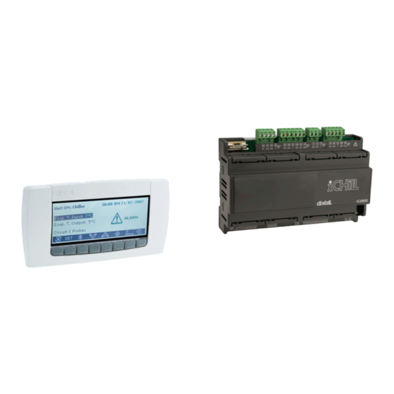
Summary of Contents for dixell Ichill 260L_D DUO
- Page 1 1592015820 User Manual IC200L/D DUO rel 1.0 User Manual Ichill 260L_D DUO Ichill 261L_D DUO (Firmware version 1.9) Pag. 1 of 149...
-
Page 2: Table Of Contents
1592015820 User Manual IC200L/D DUO rel 1.0 INDEX GENERAL FEATURES ....................8 Main Function ..............................8 ICHILL 260/261L_D FEATURES ................10 USER INTERFACE ....................11 REMOTE KEYBOARD ..................... 15 FIRST INSTALLING ....................15 WIRING CONNECTIONS ..................16 ANALOG AND DIGITAL OUTPUT CONFIGURATION ........... 26 PROGRAMMING WITH THE “HOT KEY 64”... - Page 3 1592015820 User Manual IC200L/D DUO rel 1.0 COMPRESSOR REGULATION ................51 19.1 Compressor Security Time ...........................51 CHILLER / HEAT PUMP REGULATION ..............51 20.1 Parameter Description ..........................51 20.2 Proportional Regulation ..........................52 20.3 Neutral Zone Regulation..........................53 COMPRESSORS MANAGEMENT ................54 21.1 Compressors Start- Up ..........................54 COMPRESSORS ROTATION ..................
- Page 4 1592015820 User Manual IC200L/D DUO rel 1.0 WATER PUMP OF THE CONDENSER ..............69 32.1 Condenser Pump Group ..........................70 CYCLIC OPERATION OF THE WATER PUMPS ............ 70 HOT START ......................71 LOAD MAINTENANCE .................... 71 CONDENSER FAN REGULATION ................71 36.1 Output Step Rele’...
- Page 5 1592015820 User Manual IC200L/D DUO rel 1.0 41.1 Anti-Legionella Function ..........................89 41.2 Water Pumps Management ..........................90 41.3 Sanitary Water Second Set Point .........................91 41.4 Sanitary Hot Water Production: Valves In Water Circuit ___ Fs01=1 (Air/Water, Water/Water Unit) ...91 41.4.1 - Sanitary hot water operation when the unit is producing hot water ............91 41.4.2 - Sanitary hot water operation when the unit is producing cold water ............92 41.5...
- Page 6 1592015820 User Manual IC200L/D DUO rel 1.0 49.1 Alarm ................................121 49.2 Alarm: Circuit Alarm ..........................122 49.3 Alarm: Compressor Alarm ......................... 123 TABLE OF THE PARAMETERS ................124 BLACK-OUT......................145 INSTALLING AND MOUNTING ................145 52.1 ICHILL 200 L FORMAT: Panel cut- out ....................145 52.2 ICHILL 200 L FORMAT: metal front frame ....................
- Page 7 Warning: disconnect all electrical connections before any kind of maintenance. The instrument must not be opened. In case of failure or faulty operation send the instrument back to the distributor or to “Dixell company with a detailed description of the fault.
-
Page 8: General Features
1592015820 User Manual IC200L/D DUO rel 1.0 1. GENERAL FEATURES IC260L_D/261L_D is an electronic controller for chiller unit applications having one or two circuits: Air/air Air/water Water/water Condensing unit Additional features : Heat pump with gas reversibility ... - Page 9 To control the dumper To control an external relay Complete alarm management Internal Data logger up to 100 events Supervisor / monitoring TTL output for XJ485 interface (ModBus protocol) for XWEB Dixell monitoring system Pag. 9 of 149...
-
Page 10: Ichill 260/261L_D Features
1592015820 User Manual IC200L/D DUO rel 1.0 2. ICHILL 260/261L_D FEATURES FEATURES IC290D IC291D OUTPUT RELAYS DIGITAL INPUTS configurable configurable PROBE INPUTS 6 (NTC/PTC) configurable configurable 4 (NTC/PTC/0..5V/4..20mA) configurable configurable PROPORTIONAL OUTPUTS 2 PWM outputs for condensing fan 2 0÷10V or 4÷20mA for condensing fan configurable configurable... -
Page 11: User Interface
1592015820 User Manual IC200L/D DUO rel 1.0 3. USER INTERFACE Meaning of the LEDs IC260L / IC261L models IC260L / IC261L metal front panel Pag. 11 of 149... - Page 12 1592015820 User Manual IC200L/D DUO rel 1.0 Meaning of the leds on the models VI620 - VI620S remote keyboard KEY FUNCTION ACTION FUNCTION Show chiller set point SetC and heat pump SetH Push and release In chiller or heat pump if the Energy saving or the Push once Dynamic setpoint are enabled it shows the real setpoint Setr, the led is blinking.
- Page 13 1592015820 User Manual IC200L/D DUO rel 1.0 Turn the chiller on, if the unit is on led is on Push once The led is blinking if there is a power on delay or during the pump down Turn the heat pump on, if the unit is on led is on Push once The led is blinking if there is a power on delay or during the pump down...
- Page 14 1592015820 User manual IC260_261L_D DUO FW1.9 rel. 1.0 Celsius degrees: ON for temperature measurements of probe values or parameters Fahrenheit degrees: ON for temperature measurements of probe values or parameters Bar: ON for pressure measurements of probe values, setpoint or parameters Psi: ON for pressure measurements of probe values, setpoint or parameters ON = compressor 1 active Blinking = compressor 1 delay counting...
-
Page 15: Remote Keyboard
1592015820 User manual IC260_261L_D DUO FW1.9 rel. 1.0 Meaningg of the bottom display led Led # 1 – 2 (With RTC) If the bottom display shows the RTC the 1 and 2 leds are blinking. Led # 1 – 2 In function Menu During the time counting to the next defrost for one or both circuits the led 1 and 2 are blinking. -
Page 16: Wiring Connections
1592015820 User manual IC260_261L_D DUO FW1.9 rel. 1.0 dAy: day of the month (0÷31) MntH: month (1÷12) yEAr: year (00÷99) 6. WIRING CONNECTIONS Ichill 260L 10 relays 18 digital inputs (free of voltage) 10 analogue inputs: NTC probes or through configuration 6 NTC / PTC and 4 pressure transducer 4÷20mA or ratio-metric 0÷... - Page 17 1592015820 User manual IC260_261L_D DUO FW1.9 rel. 1.0 Ichill 260D 10 digital outputs (relays) 18 digital inputs (free of voltage) 10 analogue inputs: NTC probes or through configuration 6 NTC / PTC and 4 pressure transducer 4÷20mA or ratio-metric 0÷ 5.0Volt 6 modulating outputs 1 output for remote panel (max 2 remote panels) 1 TTL output for “Hot Key 64”...
- Page 18 1592015820 User manual IC260_261L_D DUO FW1.9 rel. 1.0 Temperature probes connection (NTC – PTC Probes) Connection diagram for IC260L / IC261L / IC260D and IC261D. PbC = Probes common terminal Digital Inputs Connection diagram for IC260L / IC261L / IC260D and IC261D. GND = Digital inputs common terminal Pag.
- Page 19 1592015820 User manual IC260_261L_D DUO FW1.9 rel. 1.0 Pressure Transducer connection (4 ÷ 20mA signal) Connection diagram for IC260L / IC261L / IC260D and IC261D. 12V = Pressure trasducers common terminal Ratiometric Transducer connection (0 ÷ 5V signal) Connection diagram for IC260L / IC261L / IC260D and IC261D. Pag.
- Page 20 1592015820 User manual IC260_261L_D DUO FW1.9 rel. 1.0 PWM Output for Condensing Fan Speed Control Connection diagram for IC260L / IC261L / IC260D and IC261D. The PWM signal has to be connected to the cut of phase controller: Mod. XV05PK mono-phase , cut phase control 500 Watt (2A) Mod.
- Page 21 1592015820 User manual IC260_261L_D DUO FW1.9 rel. 1.0 Condensing Fan Control: 4÷20mA signal Connection diagram for IC260L / IC261L / IC260D and IC261D. In case of only one condensing circuit configured, the Out1 / Out2 outputs work together giving the same signal.
- Page 22 1592015820 User manual IC260_261L_D DUO FW1.9 rel. 1.0 If the dumper motor has a common pole for the 0..10V and the power supply, the connection has to be done as showed below. Ground connection has to be evaluated case per case. Proportional outputs configured to manage an external relay Connection diagram for IC260L / IC261L / IC260D and IC261D.
- Page 23 1592015820 User manual IC260_261L_D DUO FW1.9 rel. 1.0 Hot Key 64 Connection Connection diagram for IC260L / IC261L / IC260D and IC261D. The programming HOT KEY 64 allows to upload or download a copy of the parameters of the instrument (see HOT KEY paragraph).
- Page 24 1592015820 User manual IC260_261L_D DUO FW1.9 rel. 1.0 RS485 connection (IC260D / IC261D) The Ichill 260D and Ichill 261D have a RS 485 output to connect the controller to the ProgTool or a XWEB (monitoring, controlling and supervising system). Make attention to the polarity of the RS 485 signal. Remote keyboard VI620 Connection diagram for IC260L / IC261L / IC260D and IC261D.
- Page 25 1592015820 User manual IC260_261L_D DUO FW1.9 rel. 1.0 Pag. 25 of 149...
-
Page 26: Analog And Digital Output Configuration
1592015820 User manual IC260_261L_D DUO FW1.9 rel. 1.0 7. ANALOG AND DIGITAL OUTPUT CONFIGURATION Analog input Pb1 - Pb2 - Pb7 - Pb8 - Pb9 - Pb10 Parameters involved: CF08 = Configuration PB1 CF09 = Configuration PB2 CF14 = Configuration PB7 CF15 = Configuration PB8 CF16 = Configuration PB9 CF17 = Configuration PB10... - Page 27 1592015820 User manual IC260_261L_D DUO FW1.9 rel. 1.0 10 Temperature probe NTC for evaporator outlet 2 11 Temperature probe NTC for common evaporator outlet 12 Temperature probe NTC for common hot water condenser / recovery inlet 13 Temperature probe NTC for hot water condenser / recovery inlet circuit 1 14 Temperature probe NTC for hot water condenser / recovery inlet circuit 2 15 Temperature probe NTC for hot water condenser / recovery outlet circuit 1 16 Temperature probe NTC for hot water condenser / recovery outlet circuit 2...
- Page 28 1592015820 User manual IC260_261L_D DUO FW1.9 rel. 1.0 30. Recovery request circuit 1 31. Recovery request circuit 2 32. Start/End defrost circuit 1 33. Start/End defrost circuit 2 34. Energy Saving 35. Pressure switch / compressor 1 oil 36. Pressure switch / compressor 2 oil 37.
- Page 29 1592015820 User manual IC260_261L_D DUO FW1.9 rel. 1.0 14. 1° condenser fan step ON/OFF control of the circuit 2 15. 2° condenser fan step ON/OFF control of the circuit 2 16. 3° condenser fan step ON/OFF control of the circuit 2 17.
- Page 30 1592015820 User manual IC260_261L_D DUO FW1.9 rel. 1.0 67. Capacity step valve 3 compressor 3 68. By-pass gas valve compressor 3 start 69. Direct start: compressor 4 relay PW start: PW 1 of the compressor 4 Star-delta start: relay line 1 of the compressor 4 70.
-
Page 31: Programming With The "Hot Key 64
1592015820 User manual IC260_261L_D DUO FW1.9 rel. 1.0 8. PROGRAMMING WITH THE “HOT KEY 64” Download: how to program an instrument with a programmed “Hot Key” Turn off the instrument supply Insert the hot key. Turn on the power supply. Immediately the parameters are downloaded. - Page 32 1592015820 User manual IC260_261L_D DUO FW1.9 rel. 1.0 From the Pr2 level push the UP key for 2 seconds and the bottom display will show Pr3. The top display still shows PAS. After selecting the level push the SET key and the top display will show the 0 blinking value where to insert the password .
- Page 33 1592015820 User manual IC260_261L_D DUO FW1.9 rel. 1.0 Enter the programming level Pr1 Enter the Pr1 “User level ”: 1. Push the SET + DOWN keys together for 3 seconds. The top display shows PAS while the bottom display shows Pr1 labels. 2.
- Page 34 1592015820 User manual IC260_261L_D DUO FW1.9 rel. 1.0 The MENU key allows to exit from a family to reselect another without exit the Pr2 level. The MENU key allows to pass to Pr1 starting from a family label. To exit completely the programming push SET + UP.
- Page 35 1592015820 User manual IC260_261L_D DUO FW1.9 rel. 1.0 1. Keep pushed SET key; 2. Push 1 time the DOWN key and the leds 3 is off, the parameter is now available also in Pr2. To show the parameter only in Pr3: 1.
-
Page 36: Chiller / Heat Pump Selection
1592015820 User manual IC260_261L_D DUO FW1.9 rel. 1.0 2. Push SET key: the o label and the configuration number are blinking, use the UP or DOWN key and select the proper polarity ( o / c ) of the function, then push SET key to confirm it all. 3. -
Page 37: How To Switch On / Switch Off The Unit
1592015820 User manual IC260_261L_D DUO FW1.9 rel. 1.0 Analog input selection CF78 = 0 NTC, External air temperature probe > CF80+ CF81 the unit starts in chiller, NTC, External air temperature probe < CF80 the unit starts in heat pump. CF78 = 1 NTC, External air temperature probe >... -
Page 38: Display Layout
1592015820 User manual IC260_261L_D DUO FW1.9 rel. 1.0 With active contact if the unit is being switched off by keyboard it can be switched on by keyboard. If the unit is being switched off by keyboard, in order to switch on the unit from digital input it must be deactivated and activated. -
Page 39: Display Configuration
1592015820 User manual IC260_261L_D DUO FW1.9 rel. 1.0 Fig.2 14. DISPLAY CONFIGURATION The dP family of parameters allows to set a custom display read-out. The user can change the default read- out (both for instrument and remote terminals) of the measurements depending on the application. Top Display Bottom display Default read - out of the top display... - Page 40 1592015820 User manual IC260_261L_D DUO FW1.9 rel. 1.0 Cou1 circuit 1 dP01=6 temperature probe of the condenser water outlet Cou2 circuit 2 dP01=7 temperature probe of the common condenser water outlet Cout dP01=8 temperature probe of the dynamic external air setpoint dP01=9 temperature probe of the free cooling water inlet FCIn...
-
Page 41: Display Information
1592015820 User manual IC260_261L_D DUO FW1.9 rel. 1.0 dP02=15 San2 sanitary water temperature 2 dP02=16 solar panel water temperature SoLE Cdt1 circuit 1 dP02=17 temperature probe of the condenser Cdt2 circuit 2 Cdt1 circuit 1 dP02=18 pressure probe of the condenser 4÷20mA - 0.5V Cdt2 circuit 2 LP1 circuit 1 dP02=19... -
Page 42: Function Menu " M" Key
1592015820 User manual IC260_261L_D DUO FW1.9 rel. 1.0 Push and release the SET key, the leds of the circuits are off and the set value is displayed. In stand-by the bottom display shows SetC (set chiller), by pushing SET again the next label is SetH (set heat pump ). -
Page 43: Compressor Overload Alarm; Manual Reset
1592015820 User manual IC260_261L_D DUO FW1.9 rel. 1.0 11) Show the percentage of the proportional output 0 ÷ 10 Vdc Pout 12) Time counting to next defrost cycle, under heat pump mode, dF Show the probe temperatures that enabled to control the auxiliary output uS Read temperature of solar panel SoL Read temperature of the Free cooling SoL the temperature of the remote panels trEM... - Page 44 1592015820 User manual IC260_261L_D DUO FW1.9 rel. 1.0 5. Push SET and the top display blinks 0 while the bottom shows PAS. Insert the password using UP or DOWN key (see AL parameter family). If the password is OK the ArSt blinks for per 3seconds, if the password value is not correct the top display blinks 0 while the bottom shows PAS.
- Page 45 1592015820 User manual IC260_261L_D DUO FW1.9 rel. 1.0 If one circuit is disabled the bottom display shows diS alternated with the label name of the measurement selected. Circuit 1 = diS the bottom display shows b1dS = circuit 1 disabled. Circuit 2 = diS the bottom display shows b2dS = circuit 2 disabled.
- Page 46 1592015820 User manual IC260_261L_D DUO FW1.9 rel. 1.0 Enter the function Menu 1. Within the Hour function select, with UP or DOWN, the interested label: CO1H, CO2H, CO3H, CO4H, CO6H, EP1H, EP2H, CP1H, CP2H. 2. Push the SET keys for 3seconds: the top display shows the running hours blinking value, then it shows 0 to confirm the reset.
- Page 47 1592015820 User manual IC260_261L_D DUO FW1.9 rel. 1.0 If the proportional output Pou1 - Pou2 - Pou3 - Pou4 are configured to drive an external relay the display will show 0=relay off and 100=relay on. Read-out of the time counting to the next defrost The 2 times delay to next defrosts of the two circuits can be showed in the menu function.
-
Page 48: Energy Saving
1592015820 User manual IC260_261L_D DUO FW1.9 rel. 1.0 To exit to the normal display read-out push MENU or wait the time – out time. ATTENTION: THE trEm function and the labels trE1 or trE2 appear only if the CF74 = =2 or 3 (remote panel 1 configuration) or if the parameter CF75 = 2 or 3 (remote panel 2 configuration). -
Page 49: Dynamic Setpoint
1592015820 User manual IC260_261L_D DUO FW1.9 rel. 1.0 MONDAY X = 0 - Y= 1: the energy saving is disabled, the automatic on is enabled in time band 1 MONDAY X = 3 - Y= 7: the energy saving is enabled in time band 1 and time band 2, the automatic on is enabled in time band 1, time band 2 and time band 3. - Page 50 1592015820 User manual IC260_261L_D DUO FW1.9 rel. 1.0 In chiller mode the parameter Sd01 is not equal to 0. In heat pump mode the parameter Sd02 is not equal to 0. A analog input is configured as 4÷20mA for dynamic setpoint control or outside temperature Dynamic setpoint diagram Analog input configured as 4..20mA for dynamic setpoint: Analog input configured as outside temperature and positive differential:...
-
Page 51: Compressor Regulation
1592015820 User manual IC260_261L_D DUO FW1.9 rel. 1.0 19. COMPRESSOR REGULATION CF94 Working mode of the compressor 0 = chiller and heat pump 1 = only chiller 2 = only heat pump It is possible to decide how many compressors are used in chiller, heat pump and sanitary water production. parameter CO76: number of compressors to use in chiller parameter CO77: number of compressors to use in heat pump parameter CO78: number of compressors to use in sanitary water... -
Page 52: Proportional Regulation
1592015820 User manual IC260_261L_D DUO FW1.9 rel. 1.0 4= Remote keyboard 1 probe 5= Remote keyboard 2 probe 6= NTC probe temperature of the condenser common inlet 7= NTC probe temperature of the condenser 1 inlet 8= NTC probe temperature of the condenser 2 inlet 9= NTC probe temperature of the condenser 1 outlet 10= NTC probe temperature of the condenser 2 outlet 11= NTC probe temperature of the condenser common outlet... -
Page 53: Neutral Zone Regulation
1592015820 User manual IC260_261L_D DUO FW1.9 rel. 1.0 20.3 Neutral Zone Regulation Compressor regulation in chiller Compressor regulation in heat pump Pag. 53 of 149... -
Page 54: Compressors Management
1592015820 User manual IC260_261L_D DUO FW1.9 rel. 1.0 Compressor in neutral zone Par. CO53 Maximum time of work in neutral zone without insert resource When the temperature is inside the neutral zone, a timer is activated (parameter CO53); when this time is elapsed, the Ichill switch on all the compressor to avoid an stationary situation. - Page 55 1592015820 User manual IC260_261L_D DUO FW1.9 rel. 1.0 Fig. 1 Part Winding Each compressor needs two relay outputs: Part Winding coil 1 of the compressor; Part Winding coil 2 of the compressor. The time delay between coil 1 and coil 2 activation is CO11 (decimal of second, in a range 0..5 seconds). The maximum number of relay outputs is 8, this means 4 compressors managed with Part Winding start-up.
-
Page 56: Compressors Rotation
1592015820 User manual IC260_261L_D DUO FW1.9 rel. 1.0 switched off (relay K2 Fig.2). Then after the CO12 delay time the relay of the line #2 is turned on (relay K3 Fig.3). Compressor switching off: the output relay of the line #1 and line #2 are switched off together. Fig. - Page 57 1592015820 User manual IC260_261L_D DUO FW1.9 rel. 1.0 Out relay Cap. step 2 OFF Cap. step 2 ON Cap. step 2 OFF Cap. step 2 OFF Out relay Cap. step 3 OFF Cap. step 3 OFF Cap. step 3 ON Cap.
-
Page 58: Minimum Load Start- Up
1592015820 User manual IC260_261L_D DUO FW1.9 rel. 1.0 Out relay Cap. step 2 OFF Cap. step 2 OFF Cap. step 2 ON Cap. step 2 ON Out relay Cap. step OFF Cap. step OFF Cap. step 1 OFF Cap. step 1 ON Direct action with sequential step Compressor Cap. - Page 59 1592015820 User manual IC260_261L_D DUO FW1.9 rel. 1.0 To increase / decrease the power the compressor works by step of 1% of the power; every step is delayed by CO62 at the start-up of the compressor and CO71 when the compressor works normally. When the compressor inverter controlled is activated, it works at power configured by CO61 parameter for CO60 seconds;...
- Page 60 1592015820 User manual IC260_261L_D DUO FW1.9 rel. 1.0 TWO COMPRESSORS INVERTER CONTROLLED OPERATING MODE: CHILLER TWO COMPRESSORS INVERTER CONTROLLED OPERATING MODE: HEAT PUMP Pag. 60 of 149...
- Page 61 1592015820 User manual IC260_261L_D DUO FW1.9 rel. 1.0 Parameters involved: CO60 Operation time at CO61 power when the compressor inverter controlled is switched on CO61 Forced power when the compressor inverter controlled is switched on CO62 Delay to increase the power during the start up phase of the compressori inverter controlled CO63 Compressor inverter controlled operation power under whitch...
-
Page 62: Inverter Compressor In Heat Pump And External Temperature
1592015820 User manual IC260_261L_D DUO FW1.9 rel. 1.0 CO81 Maximum speed of the inverter compressors in sanitary water CO82 Outside temperature to reduce inverter compressor speed in 70.0 °C Heat pump 50.0 °F 50.0 CO83 Hysteresis temperature to reduce inverter compressor speed in 25.0 °C Heat pump... -
Page 63: Compressors With Different Capacity
1592015820 User manual IC260_261L_D DUO FW1.9 rel. 1.0 26. COMPRESSORS WITH DIFFERENT CAPACITY The function is enabled if: one circuit unit at least 2 compressor are configured the capacity of the compressors is not 0 and different for each one ... -
Page 64: Circuit Management: Saturation Or Balancing
1592015820 User manual IC260_261L_D DUO FW1.9 rel. 1.0 27. CIRCUIT MANAGEMENT: SATURATION OR BALANCING CIRCUIT SATURATION CO15 = 0 If the machine has 2 compressors in the circuit 1 and 2 compressors in the circuit 2, the sequence of activation is: compressor circuit 1 ... - Page 65 1592015820 User manual IC260_261L_D DUO FW1.9 rel. 1.0 PUMP DOWN with low pressure probe CO36 = 1 Pump down enabled during the switching off (low pressure probe) Before turning off the last compressor, the solenoid valve is closed; the compressor works until the pressure falls below CO37 or after a maximum time CO39;...
-
Page 66: Unloading
1592015820 User manual IC260_261L_D DUO FW1.9 rel. 1.0 29. UNLOADING 29.1 High Temperature Of The Evaporator Water Inlet It is possibble to use this function if there are at least 2 steps of power (two compressor or 1 compressor with partialization) for every circuit or with inverter compressor. -
Page 67: Low Temperature Of The Evaporator Water Outlet
1592015820 User manual IC260_261L_D DUO FW1.9 rel. 1.0 EXAMPLE 2 circuits and 3 compressors per circuit 6 compressors are running; if CO49 = 2 in case of unloading 2 compressors are switched off and 4 continuous to work. UNLOADING DE-ACTIVATION in HEAT PUMP MODE When the evaporator probe (orcondenser pressure or condenser temperature) increase over CO46+CO47 the unloading function is disabled and all compressor are available to work. -
Page 68: Evaporator Pump Group
1592015820 User manual IC260_261L_D DUO FW1.9 rel. 1.0 When the last compressor is switched off, the water pump / supply fan is switched off after CO18 delay from compressor. When the unit is in stand-by or remote off and the Ar09 =1, if the regulation requires the antifreeze heaters also the water pump is turned on. -
Page 69: Water Pump Of The Condenser
1592015820 User manual IC260_261L_D DUO FW1.9 rel. 1.0 Parameter Description US 47 Probe 1 selection for evaporator water pump modulation in chiller US 48 Probe 2 selection for evaporator water pump modulation in chiller US 49 Set point for maximum speed of modulationg evaporator water pump in chiller 30.0 70.0 °C... -
Page 70: Condenser Pump Group
1592015820 User manual IC260_261L_D DUO FW1.9 rel. 1.0 When the Ichill is switched on in chiller or heat pump, the water pump is immediately activated and the first compressor is switched on after CO17 delay. When the Ichill is in STD-BY or remote OFF the water pump is OFF (with a delay if CO23>0). The parameter Ar09 allows to set the status of the water pump in case of antifreeze if the Ichill is in stand-by. -
Page 71: Hot Start
1592015820 User manual IC260_261L_D DUO FW1.9 rel. 1.0 CO 90 Condenser water pump ON time 10 Sec 34. HOT START In the air air unit and in heating mode it is possible to stop the supply fan when the outlet evaporator temperature falls below FA24 degrees. -
Page 72: Output Step Rele' Condenser Fan
1592015820 User manual IC260_261L_D DUO FW1.9 rel. 1.0 FA01 and FA02 parameters define the operative mode of the condenser fans. Par. FA01 Fan regulation 0 = Output not enabled 1 = Always on 2 = ON/OFF step regulation 3 = ON/OFF continuous step regulation 4 = proportional fan speed Par. -
Page 73: Pwm Output For Fan Control
1592015820 User manual IC260_261L_D DUO FW1.9 rel. 1.0 Par FA01 = 3 ON/OFF continuous step regulation E.G.: 1 circuit and 4 step of ventilation Continuous step regulation OUT relè Gradino n° 1 Gradino n° 2 Gradino n° 3 Gradino n° 4 Out relè... -
Page 74: On/Off Regulation Of Condenser Fans
1592015820 User manual IC260_261L_D DUO FW1.9 rel. 1.0 36.5 On/Off Regulation Of Condenser Fans Condenser fan in Chiller mode. Condenser fan in Heat pump mode. 36.6 Pre-Ventilation And Post-Ventilation Pre-ventilation: Pag. 74 of 149... -
Page 75: Anti Freeze Heaters, Integration Heating Or Boiler
1592015820 User manual IC260_261L_D DUO FW1.9 rel. 1.0 in chiller and heat pump mode when first compressor is swtiched on if FA06>0 and/or FA30>0 the fan runs at maximum speed for FA06 and/or FA30. Post-ventilation: in heat pump mode if FA31>0 and outside temperature > FA32, when last compressor is switched off the condenser fan (if on at that moment) is forced at FA33 speed for FA31 seconds (outside temperature probe is required). - Page 76 1592015820 User manual IC260_261L_D DUO FW1.9 rel. 1.0 ATTENTION When the outputs are configured as heaters circuit #1 and 2 they are both controlled by the NTC probe of the common condenser outlet. Graph of the anti-freeze- integration heating - boiler heater relays Boiler function The function is enabled when: ...
-
Page 77: Auxiliary Relays
1592015820 User manual IC260_261L_D DUO FW1.9 rel. 1.0 38. AUXILIARY RELAYS Par. uS01 configuration auxiliary relay 1 Par. uS05 configuration auxiliary relay 2 0 = Not enabled 1 = Function enabled, direct action, also if the Ichill is in stand-by or remote off. 2 = Function enabled, direct action, only if the Ichill is on in chiller or heat pump (not in stand-by or remote off) 3 = Function enabled, inverse action, also if the Ichill is in stand-by or remote off... -
Page 78: Auxiliary Proportional Outputs
1592015820 User manual IC260_261L_D DUO FW1.9 rel. 1.0 US 7 70.0 °C °F 50.0 Auxiliary relay 1 winter maximum set point US 8 °C °F Auxiliary relay 1 winter set point US 9 25.0 °C °F 14.0 Auxiliary relay 1 summer differential US 10 25.0 °C... - Page 79 1592015820 User manual IC260_261L_D DUO FW1.9 rel. 1.0 1 = Function enabled, direct action, enabled also in stand-by and remote off 2 = Function enabled, direct action, enabled only if the Ichill is working in chiller or heat pump 3 = Function enabled, inverse action, enabled also in stand-by and remote off 4 = Function enabled, inverse action, enabled only if the Ichill is working in chiller or heat pump Auxiliary Proportional output: Direct action US46=0...
- Page 80 1592015820 User manual IC260_261L_D DUO FW1.9 rel. 1.0 US 22 Auxiliary proportional output n° 1 operating mode 0= Not enabled 1= Always available with direct action 2= Available only when the unit is on with direct action 3= Always available with reverse action 4= Available only when the unit is on with reverse action US 23 Analogue input configuration for auxiliary control 1...
-
Page 81: Defrost Cycle
1592015820 User manual IC260_261L_D DUO FW1.9 rel. 1.0 US 36 -30.0 °C °F US38 Analog output 2 summer minimum set point US 37 70.0 °C °F US38 50.0 Analog output 2 summer maximum set point US 38 °C °F US36 US37 Analog output 2 summer set point US 39... -
Page 82: Other Information About The Defrost
1592015820 User manual IC260_261L_D DUO FW1.9 rel. 1.0 When the condenser temperature/pressure or evaporating pressure falls below dF02 and at least one compressor is ON, the delay between two defrost dF09 starts counting. The display of the keyboard shows the symbol blinkking. -
Page 83: Forced Defrost
1592015820 User manual IC260_261L_D DUO FW1.9 rel. 1.0 40.3 Forced Defrost The function is enabled if the parameter dF19>0. It allows to make a forced defrost cycle even if the dF09 timeout counting is not expired, when the condensing/evaporating temperature/pressure is lower than dF20 setpoint for the dF19 time counting. -
Page 84: Defrost With Condenser Fan Procedure
1592015820 User manual IC260_261L_D DUO FW1.9 rel. 1.0 Parameter dF23=0 dF23=1 dF23=2 dF22=0 not possible (ACF1) not possible (ACF1) dF22=1 dF22=2 not possible (ACF1) not possible (ACF1) ATTENTION: The configuration error ACF1 is displayed if the parameter value of dF22 and dF23 is not permitted. For only one condensing unit the dF22 and dF23 values must be not equal to 0. - Page 85 1592015820 User manual IC260_261L_D DUO FW1.9 rel. 1.0 If dF01=2, it determines the maximum duration of the defrost and even if, for the other cases, the end defrost condition are still to be satisfied. dF06 defrost delay time between the 1 and the 2 circuit.
-
Page 86: Defrost Dynamic Set Point
1592015820 User manual IC260_261L_D DUO FW1.9 rel. 1.0 It determines a temperature/pressure setpoint under which the dF19 starts counting, when dF19 is expired if the temperature/pressure is still lower than dF20 the defrost is immediately executed. ATTENTION If during the dF19 counting the temperature rises over df20+dF21(differential) the process is aborted and the dF19 time reloaded. -
Page 87: Production Of Sanitary Hot Water
1592015820 User manual IC260_261L_D DUO FW1.9 rel. 1.0 41. PRODUCTION OF SANITARY HOT WATER The sanitary hot water production is enabled when the machine is switched on and disabled if the machine is OFF or in STAND-BY. The Ichill has to be configured for the proportional regulation (St11=0) and not in neutral zone. In case of machine with valve 1 and valve 2 in gas circuit and cooling and sanitary water active at the same time, the number of compressors to use is determined by CO78 parameter. - Page 88 1592015820 User manual IC260_261L_D DUO FW1.9 rel. 1.0 FS49=1 Example for machine with 3 compressors Sanitary water heaters: Sanitary water is produced using mainly the compressors; the sanitary water heaters are only used to produce sanitary water if one or more compressors are not available for regulation (due to an alarm of a compressor, activation of the unloading function,..) or if the sanitary water set-point is not reached within a configured timeframe (described in greater detail below).
-
Page 89: Anti-Legionella Function
1592015820 User manual IC260_261L_D DUO FW1.9 rel. 1.0 41.1 Anti-Legionella Function The FS12 parameter allows you to enable the anti-legionella function. FS12=0 intervals between two anti-legionella cycles; the process will have to be repeated after the FS13 time since the last anti-legionella production procedure was carried out. The counter continues to operate, regardless of whether the machine is on or off or in standby;... -
Page 90: Water Pumps Management
1592015820 User manual IC260_261L_D DUO FW1.9 rel. 1.0 FS46=3 Only compressors are used in Anti-legionella cycle Only compressors are used in the Anti-legionella cycle (heaters off); when FS14 + FS20 temperature is reached the compressors are switched off. Once reached the set point, the instrument works to maintain the set point for FS19 time; the Anti-legionella cycle lasts maximum FS29 minutes. -
Page 91: Sanitary Water Second Set Point
1592015820 User manual IC260_261L_D DUO FW1.9 rel. 1.0 41.3 Sanitary Water Second Set Point The sanitary water second set point can enabled by time bands (ES19..ES33 parameters) or digital input properly configured. In case of sanitary water second set point enabled by time bands, the Ichill must have internal clock. Par. -
Page 92: Sanitary Hot Water Operation When The Unit Is Producing Cold Water
1592015820 User manual IC260_261L_D DUO FW1.9 rel. 1.0 41.4.2 - Sanitary hot water operation when the unit is producing cold water When the production of sanitary water is required (and it has priority), it is necessary to reverse the cycle as follows: ... - Page 93 1592015820 User manual IC260_261L_D DUO FW1.9 rel. 1.0 the sanitary water circulation pump is switched on after a delay of FS27 seconds the sanitary water valve 1 is switched on after the FS10 delay the sanitary water valve 2 is switched off The following two cases could occur during the production of sanitary hot water: ...
-
Page 94: Solar Panel Management
1592015820 User manual IC260_261L_D DUO FW1.9 rel. 1.0 after the DF07/2 delay the 4-way valve status is reversed and normal regulation is restored. If chilled water is required during the production of sanitary water, operation is the same as in the previous case. -
Page 95: Unit With Hybrid Exchangers (Air / Water Unit)
1592015820 User manual IC260_261L_D DUO FW1.9 rel. 1.0 the solar panel are enabled to work (valve is open and water pump on); heating probe is defined by FS58 parameter (it is possible to set another probe, if needed). Compressors are normally managed by heating regulation. ... -
Page 96: Geothermal Free Cooling
1592015820 User manual IC260_261L_D DUO FW1.9 rel. 1.0 44. GEOTHERMAL FREE COOLING Outputs managed: relay for valve/pump management 0..10V analog output to control a modulating valve In heating the relay is OFF and the analog output is 0V. Free cooling operation mode: ... - Page 97 1592015820 User manual IC260_261L_D DUO FW1.9 rel. 1.0 Parameter Description FS21 25.0 °C °F Temperature differential to enable the freecooling function FS22 25.0 °C °F Temperature differential for the free cooling regulation …. FS34 Free cooling water pump OFF time if chiller only Free cooling FS35 Free cooling water pump ON time if chiller only Free cooling FS36...
-
Page 98: Recovery Function
1592015820 User manual IC260_261L_D DUO FW1.9 rel. 1.0 Low temperature protection If the temperature detected by probe selected with FS62 parameter is lower than FS63 set point, the free cooling is disabled. The free cooling will be enabled when temperature detected by probe selected with FS62 parameter is higher than FS63 + FS64. -
Page 99: Unit With Two Idraulic Circuit Working In Parallel
1592015820 User manual IC260_261L_D DUO FW1.9 rel. 1.0 With the recovery function enabled, the unit running in chiller and with the temperature/pressure proper condition, the unit can start the recovery of the first circuit if the corresponding digital input is active. When the digital input is active the relay of the valve for the recovery of the first circuit is activated. -
Page 100: Condenser Temperaure / Presure Condition To Enable/Disable The Recovery Cycle
1592015820 User manual IC260_261L_D DUO FW1.9 rel. 1.0 UNIT WITH BOTH THE CIRCUITS RUNNING If recovery function is enabled, if the condenser temperature/pressure condition are within the limits the circuit #1 starts the recovery (recovery valve #1 on) when the digital input #1 is activated and the circuit #2 starts the recovery (recovery valve #2 on) when the digital input #2 is activated. -
Page 101: Recovery Enabled
1592015820 User manual IC260_261L_D DUO FW1.9 rel. 1.0 46.2 RECOVERY ENABLED If the temperature/pressure decreases under the set rC06-rC07 (differential) the recovery cycle, of the circuit detected by that transducer , is enabled again. 46.3 NOTE ABOUT RECOVERY ENABLED/DISABLED To avoid long period of time with recovery function disabled and the temperature/pressure within the range rC06-rC07, the units starts counting the delay set in rC08. - Page 102 1592015820 User manual IC260_261L_D DUO FW1.9 rel. 1.0 when the number of the event is < AL20 to reset the alarm follow the procedure described in Cap. 39.2 when the number of the event is = AL20 to reset the alarm follow the procedure described in Cap. 39.3 (a password is necessary to reset the alarm) If the cause of alarm is already present, the display shows “Active”...
- Page 103 1592015820 User manual IC260_261L_D DUO FW1.9 rel. 1.0 ATTENTION With air/water or water/water units and CF01=1,2 the minimum number of events per hour is 1. AL17 Active flow input duration Within this time the flow alarm must be active and after AL17 is expired the alarm is signalled. The counter starts after AL15 and allows to filter the improvise flow reduction or the possible bubbles of air.
- Page 104 1592015820 User manual IC260_261L_D DUO FW1.9 rel. 1.0 AtSF: Overload alarm of the supply fan Label on alarm visualization menu CF01=0: After on fan when the ID is activated for AL15 time. After on pump Origin when the ID is activated for AL17. Digital input not active for AL18 time Reset Restart...
- Page 105 1592015820 User manual IC260_261L_D DUO FW1.9 rel. 1.0 AtHS Sanitary heaters overload alarm AtHS (sanitary heaters overload) Label on alarm visualization menu Digital input active Origin Reset Digital input not active Restart Manual (reset procedure in function menu) Symbol On the display the symbol is blinking Action Alarm relay + buzzer ON...
- Page 106 1592015820 User manual IC260_261L_D DUO FW1.9 rel. 1.0 Digital input configured as generic alarm with stop regulation not active after Reset the delay in Par. AL44 Restart Automatic – It becomes manual after AL42 events/hour Logged only if manuale Symbol On the display the symbol is blinking Action...
- Page 107 1592015820 User manual IC260_261L_D DUO FW1.9 rel. 1.0 ACF1 Label on alarm Heat pump unit without 4-way valve not configured visualization menu Wrong configuration of defrost parameters dF22 and dF23) ACF2 Condensing control without probe configuration. (one probe per circuit with 2 separate circuits, at least 1 probe for common cond.) ...
- Page 108 1592015820 User manual IC260_261L_D DUO FW1.9 rel. 1.0 ACF6 The total number of compressor of the 2 circuits ( CF04 + CF05 ) is: > 6 > 4 with no direct compressor start-up (CO10 ≠ 0) or the number of steps ...
- Page 109 1592015820 User manual IC260_261L_D DUO FW1.9 rel. 1.0 ACF9 Label on alarm Not Used visualization menu AC10 Compressor inverter controlled 2 anologue output configurated for the same compressor One analog output is configured as output for compressor inverter controlled but none relays is configured as compressor ...
- Page 110 1592015820 User manual IC260_261L_D DUO FW1.9 rel. 1.0 Restart Manual in function menu Symbol On the display the symbol is blinking Action Alarm relay + buzzer ON Regulation Loads Not changed Energy saving Disabled if based on RTC Unit ON/OFF Disabled if based on RTC AEun: Unloading from high temperature of the evaporator water inlet Label on alarm...
- Page 111 1592015820 User manual IC260_261L_D DUO FW1.9 rel. 1.0 ALti: low air ambient temperature (Air / Air unit only) ALti (low temperature value of the evaporator air inlet) Label on alarm visualization menu Chiller mode: CF01=0 and evaporator inlet NTC probe lower than AL26 for Origin AL28 seconds.
- Page 112 1592015820 User manual IC260_261L_D DUO FW1.9 rel. 1.0 Restart Reset procedure in Menu function Always manual AL54 = 0 Always automatic AL54 =16 From manual to utomatic if AL54 value is between 1 and 15 Symbol On the display the symbol is blinking Action Alarm Relay + and buzzer on...
- Page 113 1592015820 User manual IC260_261L_D DUO FW1.9 rel. 1.0 b1AH - b2AH Anti-freeze alarm / Low outlet air temperaure(Air/Air unit only) on heat pump mode Label on alarm b1AH (anti-freeze alarm of the circuit #1 in heat pump) visualization menu b2AH (anti-freeze alarm of the circuit #2 in heat pump) b1Ah (anti-freeze alarm signalling of the circuit #1 in heat pump) b2Ah (anti-freeze alarm signalling of the circuit #2 in heat pump) Both the labels are displayed when the alarm is coming from the evaporator...
- Page 114 1592015820 User manual IC260_261L_D DUO FW1.9 rel. 1.0 Origin With the digital input is active If AL08=1, also in stand-by or remote OFF, when the low pressure switch input is active. In defrost if AL06=1 when the compressor low pressure switch input is active.
-
Page 115: C1Pd - C2Pd – Compressor Oil Differential Pressure
1592015820 User manual IC260_261L_D DUO FW1.9 rel. 1.0 Regulation Compressor Other loads Not modified C1HP - C2HP - C3HP - C4HP - C5HP - C6HP compressor high pressure alarms C1HP ( compressor high pressure alarm 1) – … C6HP (compressor high Label on alarm pressure alarm 6) visualization menu... - Page 116 1592015820 User manual IC260_261L_D DUO FW1.9 rel. 1.0 Origin Pistons compressor: Compressor oil pressure – evaporating pressure < AL78 Screw compressor: Condensing pressure – compressor oil pressure > AL78 Reset Pistons compressor: Compressor oil pressure – evaporating pressure > AL78 + AL79 Screw compressor: Condensing pressure –...
- Page 117 1592015820 User manual IC260_261L_D DUO FW1.9 rel. 1.0 Origin Only in defrost if DF01 = 1,3 (defrost en temperature/pressure or external contact): when the defrost ends after the DF05 timeout. Reset Stand - by or remote ON-OFF. Next defrost ends for temperature/pressure. Restart Automatic if next defrost ends for temperature/pressure, otherwise manual.
- Page 118 1592015820 User manual IC260_261L_D DUO FW1.9 rel. 1.0 Reset From thermoregulation start-up and ID not active From thermoregulation start-up with evaporating pressure higher than CO37 + CO38 (differential) Restart Automatic – Manual and logged after AL21 events per hour (reset procedure in function menu).
- Page 119 1592015820 User manual IC260_261L_D DUO FW1.9 rel. 1.0 Pump running hours > Hour counter setpoint Origin Reset Hour reset in function menu Restart Manual Symbol On the display the symbol is blinking Action Alarm relay + buzzer ON Regulation Action Only display warning messages Loads Not changed...
-
Page 120: Automatic To Manual Alarm Procedure
1592015820 User manual IC260_261L_D DUO FW1.9 rel. 1.0 49. AUTOMATIC TO MANUAL ALARM PROCEDURE NUMBER OF EVENTS PER HOUR Each hour counting is divided in 16 intervals, each made of 3600 / 16 = 225 seconds (3 minuts and 45 seconds). -
Page 121: Alarm
1592015820 User manual IC260_261L_D DUO FW1.9 rel. 1.0 49.1 Alarm Alarm Alarm description Comp. Anti freeze Support Evaporator Condenser Sanitary Solar Ventilaz. Auxiliary Code heaters heaters Pump / Pump Water panel cond. relay Boiler Supply fan pump Water Cir1 Cir2 pump AP1..AP Yes (1) -
Page 122: Alarm: Circuit Alarm
1592015820 User manual IC260_261L_D DUO FW1.9 rel. 1.0 ALSF Phase sequence alarm Eeprom alarm ACF1 Configuration alarm ACF12 ArtF Faulty clock ArtC Clock error Unloading signalling from high AEUn temp. of evaporator water Low evaporator inlet temperature ALti in air/air unit High water temperature inlat AEht evaporator... -
Page 123: Alarm: Compressor Alarm
1592015820 User manual IC260_261L_D DUO FW1.9 rel. 1.0 b(n)PH Pump down alarm in stop regulation of the circuit (n) b(n)PL Pump down in regulation start-up of the circuit (n) b(n)dF Bad defrost circuit (n) b(n)Cu Unloading from condenser high temp/press of the circuit (n) b(n)Cu Unloading from evaporator low temp/press of the circuit (n) Recovery function disabled in circuit (n) b(n)rC... -
Page 124: Table Of The Parameters
1592015820 User manual IC260_261L_D DUO FW1.9 rel. 1.0 50. TABLE OF THE PARAMETERS Description Label Shows all the parameters Shows only the Thermoregulation parameters Shows only the Configuration parameters Shows only the Dynamic Setpoint parameters Shows only the Energy Saving, RTC parameters Shows only the compressor rack parameters Shows only the compressor parameters Shows only the Auxiliary Output parameters... - Page 125 1592015820 User manual IC260_261L_D DUO FW1.9 rel. 1.0 dP 3 Default display read-out configuration top / bottom 0= Configurable 1= Top display: Evaporator IN, Bottom display: Evaporator OUT 2= Top display: Condenser IN, Bottom display: Condenser OUT 3=Top display: temperature/Condensing pressure, Bottom Display: evaporating pressure Top display default read-out of the remote terminal_1 0= the read-out depends on the paremeters dP01 –...
- Page 126 1592015820 User manual IC260_261L_D DUO FW1.9 rel. 1.0 CF 18 PB1 Offset -12.0 12.0 °C °F CF 19 PB2 Offset -12.0 12.0 °C °F CF 20 PB3 Offset -12.0 12.0 °C °F -5.0 CF 21 PB4 Offset -12.0 12.0 °C °F -5.0 CF 22...
- Page 127 1592015820 User manual IC260_261L_D DUO FW1.9 rel. 1.0 CF 69 Circuit 2 output signal: 0= 0 – 10V 1= 4 ÷ 20Ma 2= PWM for mono phase fan control board Proportional output CF 70 Proportional output “out 3” 0= Not enabled 1= Modulated evaporator water pump 2= Modulated Free cooling valve 3= Not used...
- Page 128 1592015820 User manual IC260_261L_D DUO FW1.9 rel. 1.0 CF 84 Serial address CF 85 Firmware Release (only reading) CF 86 Eeprom parameter map (only reading) Regulation of unbalanced compressors (different power) CF 87 Compressor 1 capacity 100% CF 88 Compressor 2 capacity 100% CF 89 Compressor 3 capacity...
- Page 129 1592015820 User manual IC260_261L_D DUO FW1.9 rel. 1.0 Sd 29 -30.0 30.0 °C Summer temperature differential relay AUX2 °F Sd 30 -30.0 30.0 °C Winter temperature differential relay AUX2 °F Energy saving Parameters Description Risoluzione ES 1 Start of the Time band 1 (0÷24) 24.00 10 Min ES 2...
- Page 130 1592015820 User manual IC260_261L_D DUO FW1.9 rel. 1.0 CO 4 OFF delay time between two compressors or compressor and valve. During this time the led of the next resource is blinking. CO 5 Output time delay after the main power supply start-up to the unit. 10 Sec 10 sec All the loads are delayed in case of frequently power failures.
- Page 131 1592015820 User manual IC260_261L_D DUO FW1.9 rel. 1.0 CO 36 Pump down operating mode (See pump down ON/OFF function) 0= Not enabled 1= Unit off with pump–down, unit on without pump–down 2= Unit off with pump–down, unit on with pump–down 3= Chiller mode off with pump–down, chiller mode on without pump–down 4= Chiller mode off with pump–down, chiller mode on with pump–down CO 37...
- Page 132 1592015820 User manual IC260_261L_D DUO FW1.9 rel. 1.0 4 way valve CO 75 Forced time to reverse the 4 way valve when the compressor is switched off Compressors capacity CO 76 Maximum number of compressors to use in Chiller CO 77 Maximum number of compressors to use in Heat pump CO 78 Maximum number of compressors to use in Sanitary water...
- Page 133 1592015820 User manual IC260_261L_D DUO FW1.9 rel. 1.0 US 13 -30.0 °C °F US15 Auxiliary relay 2 summer minimum set point US 14 70.0 °C °F US15 50.0 Auxiliary relay 2 summer maximum set point US 15 °C °F US13 US14 Auxiliary relay 2 summer set point US 16...
- Page 134 1592015820 User manual IC260_261L_D DUO FW1.9 rel. 1.0 US 36 -30.0 °C °F US38 Analog output 2 summer minimum set point US 37 70.0 °C °F US38 50.0 Analog output 2 summer maximum set point US 38 °C °F US36 US37 Analog output 2 summer set point US 39...
- Page 135 1592015820 User manual IC260_261L_D DUO FW1.9 rel. 1.0 FA 1 Fan configuration output 0 = Not enabled 1 = Always on 2 = ON/OFF regulation with steps 3 = ON/OFF Continuous regulation 4 = Proportional speed control FA 2 Fan operating mode 0= Dependent from the compressor 1= Independent from the compressor FA 3...
- Page 136 1592015820 User manual IC260_261L_D DUO FW1.9 rel. 1.0 FA 22 Over ride CUT- OFF in Heat pump. To set a temperature/pressure differential to keep 25.0 °C the minimum fan speed. °F 14.0 FA 23 Night speed in Heat pump. To set the maximum fan speed percentage value (30..100%), it is related to the fan power supply.
- Page 137 1592015820 User manual IC260_261L_D DUO FW1.9 rel. 1.0 Ar 15 Setpoint for boiler heaters (on) in chiller -30.0 70.0 °C °F Ar 16 Proportional band for boiler heaters in chiller -30.0 70.0 °C °F Boiler function in heat pump Ar 17 Setpoint for boiler heaters (on) in HP -30.0 70.0...
- Page 138 1592015820 User manual IC260_261L_D DUO FW1.9 rel. 1.0 dF 17 Fan control during defrost / dripping time 0= Not enabled 1= Only in defrost 2= For both functions defrost / dripping time dF 18 Pressure / temperature setpoint to force the ventilation ON during the defrost. -30.0 70.0 °C...
- Page 139 1592015820 User manual IC260_261L_D DUO FW1.9 rel. 1.0 dF 39 -50.0 30.0 °C Outside temperature differential of the Defrost dinamic set point °F Heat recovery Parameters Description m. u. Resolution rC 1 Sanitary water regulation mode rC 2 Recovery modes 0 = not enabled 1 = 2 indipendent circuit 2 = both the circuit in parallel...
- Page 140 1592015820 User manual IC260_261L_D DUO FW1.9 rel. 1.0 FS 34 Free cooling water pump OFF time if chiller only Free cooling FS 35 Free cooling water pump ON time if chiller only Free cooling FS 36 Free cooling maximum time FS 37 Set point Free cooling -50.0...
- Page 141 1592015820 User manual IC260_261L_D DUO FW1.9 rel. 1.0 AL 2 Low pressure alarm delay from digital input after compressor stop if the low pressure switch is used for the pump down. 10 Sec AL02= 0 low pressure alarm not enable with compressor OFF AL02≠...
- Page 142 1592015820 User manual IC260_261L_D DUO FW1.9 rel. 1.0 AL 29 Maximum number of alarm events anti-freeze, low ambient air temperature or low outlet air temperature before changing from automatic to manual alarm reset: Always manual reset if AL29 = 0 Always automatic reset if AL29 = 16 From automatic to manual if AL29 = 1.
- Page 143 1592015820 User manual IC260_261L_D DUO FW1.9 rel. 1.0 AL 50 Functioning generic alarm n° 2 0= only signal always automatic reset 1= the alarm block the unit reset depends on the value of parameter AL51 AL 51 Maximum number of generic alarm events before turning the alarm from automatic to manual: Always manual AL51 = 0 Always automatic AL51 =16...
- Page 144 1592015820 User manual IC260_261L_D DUO FW1.9 rel. 1.0 AL 86 Flow switch alarm reset mode 0= Always manual 1= automatic reset after 1 minute 2= automatic reset after 2 minutes 250= automatic reset after 250 minutes AL 87 Evaporator/sanitary water flow switch by-pass time during Out1 / Out2 commutation Pag.
-
Page 145: Black-Out
1592015820 User manual IC260_261L_D DUO FW1.9 rel. 1.0 51. BLACK-OUT After the black-out is restored: 1. The instrument resores the same operating mode lost after the supply failure. 2. If active, the defrost is aborted. 3. All the timers and time parameters are reloaded. 4. -
Page 146: Ichill 200 Din Format Series
1592015820 User manual IC260_261L_D DUO FW1.9 rel. 1.0 52.3 ICHILL 200 DIN FORMAT SERIES IC260D - IC261D (10 DIN modules) WARNING: all the measure showed in the figure below are expressed in mm. 52.4 VERTICAL BOARDS VI620 – PANEL CUT-OUT The remote terminals are for panel mounting, panel cut-out 72x56 mm, and screwed with two screws. -
Page 147: Electrical Connections
1592015820 User manual IC260_261L_D DUO FW1.9 rel. 1.0 53. ELECTRICAL CONNECTIONS The instrument is provided with: 3 removable terminal blocks MOLEX with 0.5 mm wires: 16 / 8 /22 ways for digital / analogue inputs and modulating outputs 4 removable screw terminal block STELVIO for 2.5 mm wires connection: 3 / 4 / 5 / 6 ways for the relay outputs. - Page 148 1592015820 User manual IC260_261L_D DUO FW1.9 rel. 1.0 Power supply 230Vac Input 0 - 230Vac output -10 - 65°C Operating temperature Naylon supports 15mm Height XV05PK XV10PK XW22PK Model 25mm 42mm 64mm Connections A 1(+), 2(-) PWM input control B 3(+), 4(-) PWM output repetition signal Phase Neutral...
-
Page 149: Technical Data
1592015820 User manual IC260_261L_D DUO FW1.9 rel. 1.0 55. TECHNICAL DATA Ichill 260L / Ichill 261L Housing: self extinguishing ABS. Case: frontal 185x38 mm; depth 70mm Mounting: panel mounting in a 150x31mm panel cut-out Frontal protection: IP65 with gasket Ichill 260D / Ichill 261D Housing: self extinguishing ABS.
Need help?
Do you have a question about the Ichill 260L_D DUO and is the answer not in the manual?
Questions and answers