Table of Contents
Advertisement
Quick Links
Advertisement
Table of Contents

Subscribe to Our Youtube Channel
Related Manuals for Ledj LEDJ195


Summary of Contents for Ledj LEDJ195
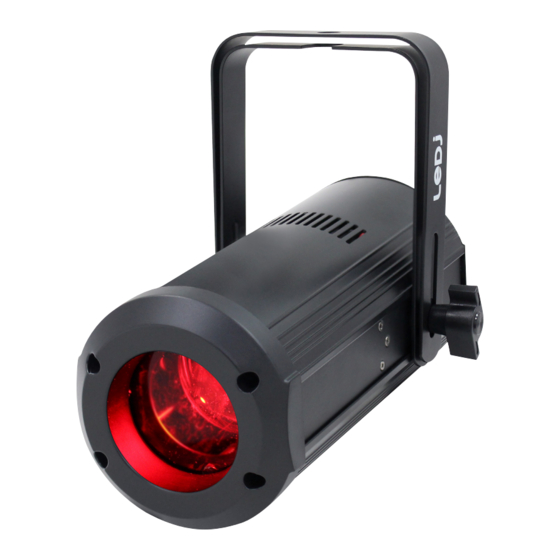
- Page 1 Ninja Zoom 250 User Manual Order code: LEDJ195...
-
Page 2: Safety Advice
Safety advice WARNING FOR YOUR OWN SAFETY, PLEASE READ THIS USER MANUAL CAREFULLY BEFORE YOUR INITIAL START-UP! • Before your initial start-up, please make sure that there is no damage caused during transportation. • Should there be any damage, consult your dealer and do not use the equipment. • To maintain the equipment in good working condition and to ensure safe operation, it is necessary for the user to follow the safety instructions and warning notes written in this manual. • Please note that damages caused by user modifications to this equipment are not subject to warranty. CAUTION! CAUTION! TAKE CARE USING KEEP THIS EQUIPMENT THIS EQUIPMENT! AWAY FROM RAIN, HIGH VOLTAGE-RISK MOISTURE AND LIQUIDS OF ELECTRIC SHOCK!! IMPORTANT:... - Page 3 • Fan cooled FULL ON 3390 70.7 39.8 25.4 1220 76.3 48.8 Specifications Ninja Zoom 250 33.8 8.45 5.41 Power consumption 1630 65.1 Power supply 100~240V, 50/60Hz Fuse F1A 250V 4° 29° Dimensions 221 x 183 x 280mm Weight 2.5kg Order code LEDJ195 183mm 280mm www.prolight.co.uk Ninja Zoom 250 User Manual...
-
Page 4: Technical Specifications
Technical specifications DMX INPUT DMX OUTPUT SAFETY MENU DOWN ENTER FUSE: F1A 250V 100-240V~50/60Hz POWER POWER INPUT OUTPUT 01 - Earth point 02 - Safety eye 07 - PowerCON input 03 - LED display 08 - PowerCON output In the box: 1 x fixture, 04 - Function buttons 09 - Fuse F1A 250V 1 x power cable 05 - 3-Pin DMX input 10 - Hanging bracket & 1 x user manual 06 - 3-Pin DMX output 11 - Hanging bracket adjustable knob www.prolight.co.uk Ninja Zoom 250 User Manual... -
Page 5: Master Setting
Operating instructions 0 0 1 A d d r DMX address settings 5 1 2 5 C H C H N d 7 C H DMX channel settings 1 1 C H N A S t Master setting O F F S L 1 S L n d Slave setting... -
Page 6: Calibration Settings
Operating instructions L E d LED display backlight setting O F F d I S P d I S P Display inverse setting d S I p r E d r 1 2 5 r 2 5 5 g r E E g 1 2 5 g 2 5 5 b A L A... - Page 7 Operating instructions DMX mode: Operating in a DMX control mode environment gives the user the greatest flexibility when it comes to customising or creating a show. In this mode you will be able to control each individual trait of the fixture and each fixture independently. To access the DMX address mode, press the “MENU” button and use the “UP” and “DOWN” buttons to Addr show on the LED display. Now press the “ENTER” button and use the “UP” and “DOWN” buttons to set the required DMX address. Press the “ENTER” button to confirm the setting. To access the DMX channel mode, press the “MENU” button and use the “UP” and “DOWN” buttons to CHnd show on the LED display. Now press the “ENTER” button and use the “UP” and “DOWN” buttons to choose one of the 1/7 or 11 DMX channel modes. Press the “ENTER” button to confirm the setting. To exit out of any of the above options, press the “MENU” button. DMX channel modes: Channel Value Function 000-255 Red dimmer (0-100%) 000-255 Green dimmer (0-100%) 000-255 Blue dimmer (0-100%) 000-255 White dimmer (0-100%) No function 001-004 Colour Macro 1 005-008 Colour Macro 2 009-012 Colour Macro 3 013-016 Colour Macro 4 017-020 Colour Macro 5...
- Page 8 DMX channel modes cont: Channel Value Function 077-080 Colour Macro 20 081-084 Colour Macro 21 085-088 Colour Macro 22 089-092 Colour Macro 23 093-096 Colour Macro 24 097-100 Colour Macro 25 101-104 Colour Macro 26 105-108 Colour Macro 27 109-112 Colour Macro 28 113-116 Colour Macro 29 117-120 Colour Macro 30 121-124 Colour Macro 31 125-128 Colour Macro 32 129-132 Colour Macro 33 133-136 Colour Macro 34 137-140 Colour Macro 35 141-144 Colour Macro 36 145-148 Colour Macro 37...
- Page 9 DMX channel modes cont: Channel Value Function 229-232 Colour Macro 58 233-236 Colour Macro 59 237-240 Colour Macro 60 5 cont. 241-244 Colour Macro 61 245-248 Colour Macro 62 249-252 Colour Macro 63 253-255 Colour Macro 64 000-031 Blackout 032-063 LED on 064-095 Strobe (slow-fast) 096-127 LED on 128-159 Pulse strobe (slow-fast) 160-191 LED on 192-223 Random strobe (slow-fast) 224-225 LED on 000-255 Master dimmer (0-100%) 000-255 Colour temperature (3000K-7200K) 000-255...
-
Page 10: Master/Slave Mode
Operating instructions Master/slave mode: To set the master unit, press the “MENU” button and use the “UP” and “DOWN” buttons to show NASt on the LED display. Now press the “ENTER” button and use the “UP” and “DOWN” buttons to choose . Press the “ENTER” button to confirm the setting. Then select your desired program. To set the other units in slave mode, press the “MENU” button and use the “UP” and “DOWN” buttons SLnd to show on the LED display. Now press the “ENTER” button and use the “UP” and “DOWN” SL 1 SL 2 buttons to choose either or . Press the “ENTER” button to confirm the setting. The unit will now run in sequence with the master unit. To exit out of any of the above options, press the “MENU” button. Please ensure that all slave units are set to the same DMX channel mode as the master unit. Show modes: SHNd To access the built-in show modes press “MENU” until the display shows on the LED display. Press “ENTER” to confirm the setting. Use the “UP” and “DOWN” buttons to select a program from SH 0 SH 9 . Press the “ENTER” button to confirm the setting. To change the speed of the selected program (except Show 0) press the “ENTER” button and then use SP00 SP99 the “UP” and “DOWN” buttons to select any value from Press the “ENTER”... - Page 11 Operating instructions DMX signal lost: To change what the unit does when the DMX signal is lost, press the “MENU” button and use the “UP” dNSt and “DOWN” buttons to show on the LED display. Now press the “ENTER” button and use the bLNd LAst “UP” and “DOWN” buttons to choose between (Blackout) or (Hold Last Command). Press the “ENTER” button to confirm the setting. To exit out of any of the above options, press the “MENU” button. Dimming curves: To access the dimmer curves setting, press the “MENU” button and use the “UP” and “DOWN” buttons CUrV to show on the LED display. Now press the “ENTER” button and use the “UP” and “DOWN” ISqU SCUr buttons to choose between (Linear), (Square law), (Inverse square law) or (S-Curve). Press the “ENTER” button to confirm the setting. To exit out of any of the above options, press the “MENU” button. Dimming speed: To access the dimmer speed setting, press the “MENU” button and use the “UP” and “DOWN” buttons to show on the LED display. Now press the “ENTER” button and use the “UP” and “DOWN” SNoo FAst buttons to choose between (Smooth) or (Fast). Press the “ENTER” button to confirm the setting.
- Page 12 Operating instructions Colour calibration setting: To access the colour calibration setting, press the “MENU” button and use the “UP” and “DOWN” bALA buttons to show shows on the LED display. Now press the “ENTER” button and use the “UP” and “DOWN” buttons to select the colour to be grEE bLUE UHIt adjusted, red ( ), green ( ), blue ( ) and white ( ). r. 1 25 r. 2 55 Press the “ENTER” button and use the “UP” and “DOWN” buttons to adjust between Press the “ENTER” button and repeat for green ( ), blue ( ) and white ( Value: 125 - 255 (125 = low brightness, 255 = high brightness) To exit out of any of the above options, press the “MENU” button.
-
Page 13: Fixture Temperature
Operating instructions Fixture temperature: To display the fixture temperature, press the “MENU” button and use the “UP” and “DOWN” buttons tENp to show on the LED display. Press the “ENTER” button and the fixture temperature will be displayed. To exit out of any of the above options, press the “MENU” button. Fixture hours: To display the fixture hours, press the “MENU” button and use the “UP” and “DOWN” buttons to show FHrS on the LED display. Press the “ENTER” button and the fixture hours will be displayed. To exit out of any of the above options, press the “MENU” button. Reset factory defaults: To reset the factory defaults, press the “MENU” button and use the “UP” and “DOWN” buttons to show FACt on the LED display. Now press the “ENTER” button and use the “UP” and “DOWN” buttons to choose . Press the “ENTER” button and the unit will reset to factory defaults. To exit out of any of the above options, press the “MENU” button. Software version: To display the software version , press the “MENU” button and use the “UP” and “DOWN” buttons to show on the LED display. Press the “ENTER” button and the software version will be displayed. To exit out of any of the above options, press the “MENU” button. Zoom home position adjustment: To access the offset menu for the zoom home position adjustment setting, press the “MENU” OSEt button once and hold the “ENTER” button for 3 seconds to display on the LED display. ZOON Now press the “ENTER” button to display . Press the “ENTER” button and use the “UP”... -
Page 14: Dmx Setup
DMX setup Setting the DMX address: The DMX mode enables the use of a universal DMX controller. Each fixture requires a “start address” from 1- 511. A fixture requiring one or more channels for control begins to read the data on the channel indicated by the start address. For example, a fixture that occupies or uses 7 channels of DMX and was addressed to start on DMX channel 100, would read data from channels: 100,101,102,103,104,105 and 106. Choose a start address so that the channels used do not overlap. E.g. the next unit in the chain starts at 107. DMX 512: DMX (Digital Multiplex) is a universal protocol used as a form of communication between intelligent fixtures and controllers. A DMX controller sends DMX data instructions form the controller to the fixture. DMX data is sent as serial data that travels from fixture to fixture via the DATA “IN” and DATA “OUT” XLR terminals located on all DMX fixtures (most controllers only have a data “out” terminal). DMX linking: DMX is a language allowing all makes and models of different manufactures to be linked together and operate from a single controller, as long as all fixtures and the controller are DMX compliant. To ensure proper DMX data transmission, when using several DMX fixtures try to use the shortest cable path possible. The order in which fixtures are connected in a DMX line does not influence the DMX addressing. For example; a fixture assigned to a DMX address of 1 may be placed anywhere in a DMX line, at the beginning, at the end, or anywhere in the middle. When a fixture is assigned a DMX address of 1, the DMX controller knows to send DATA assigned to address 1 to that unit, no matter where it is located in the DMX chain. DATA cable (DMX cable) requirements (for DMX operation): This fixture can be controlled via DMX-512 protocol. The DMX address is set on the back of the unit. Your unit and your DMX controller require a standard 3-pin XLR connector for data input/output, see image below. Further DMX cables can be purchased from all good sound and lighting suppliers or Pro Light Concepts dealers. -
Page 15: Line Termination
DMX setup Notice: Be sure to follow the diagrams below when making your own cables. Do not connect the cables shield conductor to the ground lug or allow the shield conductor to come in contact with the XLRs outer casing. Grounding the shield could cause a short circuit and erratic behaviour. Special note: Line termination: When longer runs of cable are used, Termination reduces signal transmission you may need to use a terminator on problems and interference. It is always advisable to connect a DMX terminal, the last unit to avoid erratic behaviour. (resistance 120 Ohm 1/4 W) between pin 2 Using a cable terminator will decrease (DMX-) and pin 3 (DMX+) of the last fixture. the possibilities of erratic behaviour. (3-pin - Order ref: CABL90, 5-pin - Order ref: CABL89) 5-pin XLR DMX connectors: Some manufactures use 5-pin XLR connectors for data transmission in place of 3-pin. 5-pin XLR fixtures may be implemented in a 3-pin XLR DMX line. When inserting standard 5-pin XLR connectors in to a 3-pin line a cable adaptor must be used. The diagram below details the correct cable conversion. -
Page 16: Weee Notice
WEEE notice Correct Disposal of this Product (Waste Electrical & Electronic Equipment) (Applicable in the European Union and other European countries with separate collection systems) This marking shown on the product or its literature, indicates that it should not be disposed with other household wastes at the end of its working life. To prevent possible harm to the environment or human health from uncontrolled waste disposal, please separate this from other types of wastes and recycle it responsibly to promote the sustainable reuse of material resources. Household users should contact either the retailer where they purchased this product, or their local government office, for details of where and how they can take this item for environmentally safe recycling. Business users should contact their supplier and check the terms and conditions of the purchase contract. This product should not be mixed with other commercial wastes for disposal. www.prolight.co.uk Ninja Zoom 250 User Manual...
Need help?
Do you have a question about the LEDJ195 and is the answer not in the manual?
Questions and answers