
Subscribe to Our Youtube Channel
Related Manuals for Raymarine ECI-100


Summary of Contents for Raymarine ECI-100
-
Page 1: Installation Instructions
ECI-100 Engine & Contr Interf ace Installation instructions Date: 12-2013 Document number: 87202-2-EN © 2013 Raymarine UK Limited... - Page 2 , RayTech Navigator, Sail Pilot, SeaTalk, SeaTalk , SeaTalk and Sportpilot are registered trademarks of Raymarine UK Limited. RayTalk, Seahawk, Smartpilot, Pathfinder and Raymarine are registered trademarks of Raymarine Holdings Limited. FLIR is a registered trademark of FLIR Systems, Inc. and/or its subsidiaries.
-
Page 3: Table Of Contents
Chapter 6 System checks and troubleshooting 6.1 Initial power on test 6.2 Further information 6.3 Troubleshooting Chapter 7 Maintenance 7.1 Routine checks 7.2 Unit cleaning instructions Chapter 8 Technical support 8.1 Raymarine customer support 8.2 Viewing product information Chapter 9 Technical specification... -
Page 4: Chapter 1 Important Information
Raymarine UK Ltd. declares that this product is compliant with Disclaimer the essential requirements of EMC directive 2004/108/EC. Raymarine does not warrant that this product is error-free or that it is compatible with products manufactured by any person or entity other than Raymarine. -
Page 5: Product Disposal
Directive requires the recycling of waste electrical and electronic equipment. Whilst the WEEE Directive does not apply to some Raymarine products, we support its policy and ask you to be aware of how to dispose of this product. Warranty registration It is important that you register your product to receive full warranty benefits. -
Page 6: Chapter 2 Document And Product Information
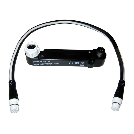
Chapter 2: Document and product information Chapter contents • 2.1 Document information • 2.2 Product overview Document and product information... -
Page 7: Document Information
• Yamaha Helm Master Description Part number Note: For systems containing more than 2 steering engines refer to the Raymarine website for compatibility information. ECI–100 Installation instructions 88026 / 87202 Installation of an ECI–100 unit and connection to a wider system of marine electronics. -
Page 8: Chapter 3 Planning The Installation
Chapter 3: Planning the installation Chapter contents • 3.1 Installation checklist • 3.2 Parts supplied • 3.3 Required additional components • 3.4 Compatible multifunction displays • 3.5 Compatible autopilot systems • 3.6 Software updates • 3.7 Tools required • 3.8 Typical systems •... -
Page 9: Installation Checklist
3.1 Installation checklist 3.2 Parts supplied Installation includes the following activities: The following items are supplied with your product. Installation Task Item Description Quantity Plan your system. ECI–100 (Engine & Control Interface) Obtain all required equipment and tools. Site all equipment. 400 mm (1.3 ft) SeaTalk spur cable (A06038) -
Page 10: Required Additional Components
CAN bus. Refer to Chapter 10 Spares • gS Series. and accessories for suitable adaptor cables. • To enable steering control a compatible Raymarine autopilot is Multifunction display software requirements required. Refer to 3.5 Compatible autopilot systems for a list of compatible products. -
Page 11: Compatible Autopilot Systems
• You can update the software for your product using a connected and compatible multifunction display. • Refer to raymarine for the latest software updates and the software update procedure for your product. • If in doubt as to the correct procedure for updating your product software, refer to your dealer or Raymarine technical support. -
Page 12: Tools Required
3.7 Tools required 3.8 Typical systems Product installation requires the following tools: Important: Do NOT connect 2 or more ECI units to the same engine CAN bus. Item Description Quantity Power drill Example: basic system — engine interface only In the example below the unit is used as an engine interface only, the unit will interface with all engines on the same CAN bus. -
Page 13: Warnings And Cautions
3.9 Warnings and cautions Item Description Multifunction display Important: Before proceeding, ensure that you have read and understood the warnings and cautions provided in the Vessel engines (Connection to engine’s CAN bus) Chapter 1 Important information section of this document. Engine specific adaptor cables ECI units SeaTalk... -
Page 14: General Location Requirements
3.10 General location requirements 3.11 Product dimensions Important considerations when choosing a suitable location for your product. This product is suitable for mounting below decks. The product should be mounted where it will be: • protected from physical damage and excessive vibration. •... -
Page 15: Chapter 4 Cables And Connections
Chapter 4: Cables and connections Chapter contents • 4.1 General cabling guidance • 4.2 Connections overview • 4.3 Power connection • 4.4 Data and control connections Cables and connections... -
Page 16: General Cabling Guidance
SeaTalk spur correct type, supplied by Raymarine. the supplied spur cables. Refer • Ensure that any non-Raymarine cables are of the correct cable. Chapter 10 Spares and quality and gauge. For example, longer power cable runs may require larger wire gauges to minimize voltage drop along the accessories. -
Page 17: Power Connection
A single ground point should be used for all equipment. The unit can be grounded by connecting the shield (drain) wire • Raymarine recommends a minimum wire gauge of 18AWG of the power cable to the vessel's RF ground point. On vessels (0.82 mm... -
Page 18: Data And Control Connections
CAN bus as other 3 party gateway CAN bus hub products. The ECI-100 should be used to replace existing gateway products in your system. Multi CAN bus connection On vessels which have a dedicated CAN bus for each engine, 1 Note: The illustrations below are examples only. -
Page 19: Chapter 5 Mounting
Chapter 5: Mounting Chapter contents • 5.1 Mounting the unit Mounting... -
Page 20: Mounting The Unit
5.1 Mounting the unit The ECI is designed to be surface mounted. Before mounting the unit ensure that you have: • Identified the routes that the cables will take. D12973-1 1. Switch off the vessel’s power supply. 2. Check the selected location for the unit, a clear, flat area is required, which is safe to have screws fitted to. -
Page 21: Chapter 6 System Checks And Troubleshooting
Chapter 6: System checks and troubleshooting Chapter contents • 6.1 Initial power on test • 6.2 Further information • 6.3 Troubleshooting System checks and troubleshooting... -
Page 22: Initial Power On Test
The troubleshooting information provides possible causes and corrective action required for common problems associated with marine electronics installations. All Raymarine products are, prior to packing and shipping, subjected to comprehensive test and quality assurance programs. However, if you experience problems with the operation of your product this section will help you to diagnose and correct problems in order to restore normal operation. - Page 23 Network problem. Check that all required equipment is connected to the network. missing from some but not all displays. Check the status of the Raymarine network Switch. Check that SeaTalk / RayNet cables are free from damage. Software mismatch between equipment Contact Raymarine technical support.
-
Page 24: Led Indications
Wait for download to complete — progress (longer than 6 Multifunction display will indicate when seconds.) software download is completed. Note: If any other LED sequence other than described above is seen and persists please contact Raymarine technical support. System checks and troubleshooting... -
Page 25: Chapter 7 Maintenance
Chapter 7: Maintenance Chapter contents • 7.1 Routine checks • 7.2 Unit cleaning instructions Maintenance... -
Page 26: Routine Checks
7.1 Routine checks 7.2 Unit cleaning instructions The following periodic checks should be made: The unit does not require regular cleaning. However, if you find it necessary to clean the unit, please follow the steps below: • Examine cables for signs of damage, such as chafing, cuts or 1. -
Page 27: Chapter 8 Technical Support
Chapter 8: Technical support Chapter contents • 8.1 Raymarine customer support • 8.2 Viewing product information Technical support... -
Page 28: Raymarine Customer Support
Raymarine provides a comprehensive customer support service. You can view information about your unit from the Diagnostics You can contact customer support through the Raymarine menu on a compatible multifunction display. This option displays website, telephone and e-mail. If you are unable to resolve a information such as product serial number and software version. - Page 29 Chapter 9: Technical specification Chapter contents • 9.1 Technical specification Technical specification...
-
Page 30: Chapter 9 Technical Specification
9.1 Technical specification Physical specification Dimensions • Length: 109.2 mm (4.3 in) • Height: 30.2 mm (1.19 in) • Width: 21.35 mm (0.84 in) Weight 43 g (1.52 oz) Power specification Engine CAN bus SeaTalk (DeviceNet) Nominal supply 12 V dc 12 to 24 V dc voltage 10.8 V to 16 V dc... - Page 31 Chapter 10: Spares and accessories Chapter contents • 10.1 Spares and accessories • 10.2 SeaTalk cables and accessories Spares and accessories...
- Page 32 10.1 Spares and accessories 10.2 SeaTalk cables and accessories Engine specific adaptor cables SeaTalk cables and accessories for use with compatible products. Engine Part Description connector ECI connector number Description Part No Notes E70240 Volvo EVC link SeaTalk starter kit T70134 Includes: cable –...
- Page 33 Description Part No Notes A80001 SeaTalk Inline Provides direct connection of terminator a spur cable to the end of a backbone cable. No T-piece required. SeaTalk Blanking plug A06032 R12112 ACU / SPX SeaTalk Connects an SPX course spur cable 0.3 m (1.0 ft) computer or an ACU to a SeaTalk backbone.
- Page 34 Appendix A Supported messages The table below shows a list of the standard parameters and messages that the unit supports. Standard J1939 Engine Parameter Engine Speed 61444 Engine Oil 65262 Temperature Engine Temperature 65262 65263 Engine Oil Pressure Engine Coolant 65263 Pressure Engine Fuel Pressure...
Need help?
Do you have a question about the ECI-100 and is the answer not in the manual?
Questions and answers