Table of Contents
Advertisement
Advertisement
Table of Contents

Subscribe to Our Youtube Channel
Summary of Contents for PowerTech PC170
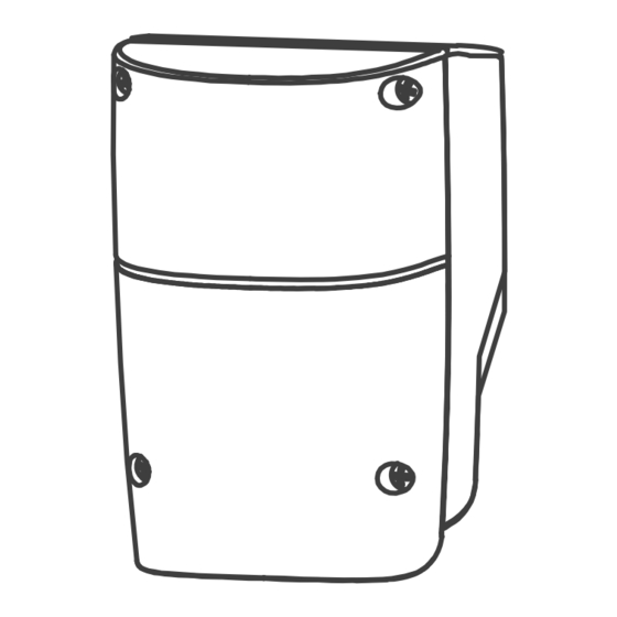
- Page 1 PC170 Control Box 24V DC GEAR MOTOR FOR RESIDENTIAL USER MANUAL...
-
Page 2: Table Of Contents
INDEX CONTROL BOX SETTING SW1 DIP SWITCH SETTING 2.1.1 SLOWDOWN ADJUSTMENT (DIP 1. SLOW) 2.1.2 OVER-CURRENT ADJUSTMENT (DIP 2.OVER C1 & DIP 3.OVER C2) 2.1.3 GATE AUTO-CLOSE ADJUSTMENT (DIP 4.AUTO C1, DIP 5.AUTO C2 & DIP 6.AUTO C3) 2.1.4 PEDESTRIAN MODE ADJUSTMENT (DIP 7.P MODE) 2.1.5 FLASHING LIGHT ADJUSTMENT (DIP 8.LIGHT) SW2 DIP SWITCH SETTING 2.2.1 PHOTOCELL ADJUSTMENT (DIP 1.PHOTO1, DIP 2.PHOTO2) -
Page 3: Control Box
1. CONTROL BOX CONTROL BOX INSTALLATION 1. Decide the installation position of control box first, it is suggested to be installed near the gate and should be protected from possible damage. Be aware of the motor cable length before deciding the installation position. 2. - Page 4 Figure 1(4) Transformer Antenna LED1 LED2 LED3 LED4 10 11 12 13 14 15 16 17 14 15 16 17 Latch Key Selector Push Button Flashing Light CONTROL BOX...
-
Page 5: Setting
2). SETTING Default Setting SW1:Set SW3:Set 1. Slow 1. OFF 1. Remote_1 1. ON 2. Over_C1 2. OFF 2. Remote_2 2. OFF 3. Over_C2 3. OFF 3. Ph_conn1 3. ON 4. Auto_C1 4. OFF 4. Ph_conn2 4. ON LED1 5. Auto_C2 5. -
Page 6: Pedestrian Mode Adjustment (Dip 7.P Mode)
2.1.4 PEDESTRIAN MODE ADJUSTMENT (DIP 7.P MODE) ON: Press button B on the remote to operate to pedestrian mode by open single gate to 45 degree OFF: The pedestrian mode is disabled. Single gate will fully open and close 2.1.5 FLASHING LIGHT ADJUSTMENT (DIP 8.LIGHT) ON: The flashing light blinks for 3 seconds before the gate moves, and blinks simultaneously during the movement. -
Page 7: Close Delay Of Dual Gate Operation Adjustment (Dip 3.Delay1, Dip 4.Delay2)
2.2.2 CLOSE DELAY OF DUAL GATE OPERATION ADJUSTMENT (DIP 3.DELAY1, DIP 4.DELAY2) Close/Open delay of two leaves of gate can be adjusted from 2 to 6 seconds DIP switch Open Delay Close Delay Dip3. Delay 1 Dip4. Delay 2 2 sec 3 sec 2 sec 4 sec... -
Page 8: Transmitter Memorize
2.4 TRANSMITTER MEMORIZING PROCESS Press “RF-learn” button for 2 seconds, and the Blue LED is on; then press the transmitter (A) button; the Blue LED will blink twice and then be off. The system learning is complete. Blue LED ON RF-Learn Blue LED OFF Blue LED blinks twice... -
Page 9: Gate Operation (Optional)
2.6 GATE OPERATION Press the button “A” on the transmitter for dual-gate operation. Press the button “B” on the transmitter for single-gate operation in either single-gate or dual-gate installation. 2.7 GATE-MOVING LOGIC (A) In gate-opening phase: The gates stop if the transmitter/push button/key selector is activated, and close when the transmitter/push button/key selector is reactivated. -
Page 10: Trouble Shooting
3. TROUBLE SHOOTING Overheated Back-up Batteries Check the wiring connection of the batteries. The gate doesn’t move when pressing the 1. Check if LED3 or 4 is “ON”. button of the transmitter 2. Check if the voltage of the batteries is below 22V. 3. -
Page 11: Photocell Installation Guide
TX: Connect terminals 1 and 2 on the transmitter with the terminals G and +12V on the PC170 PCB. RX: Connect terminals 1, 2 and 4 on the receiver with the terminals G, FO+ and FO1 on the PC170. And use an extra wire to connect terminals 2 and 5 on the receiver as a bridge. - Page 12 34100-093-01-B...
Need help?
Do you have a question about the PC170 and is the answer not in the manual?
Questions and answers