Table of Contents
Advertisement
Quick Links
Advertisement
Table of Contents

Subscribe to Our Youtube Channel
Related Manuals for Ledj LEDJ472


Summary of Contents for Ledj LEDJ472
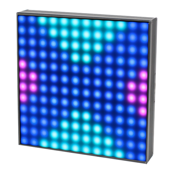
- Page 1 TPix Panel User Manual Order code: LEDJ472...
-
Page 2: Safety Advice
Safety advice WARNING FOR YOUR OWN SAFETY, PLEASE READ THIS USER MANUAL CAREFULLY BEFORE YOUR INITIAL START-UP! • Before your initial start-up, please make sure that there is no damage caused during transportation. • Should there be any damage, consult your dealer and do not use the equipment. • To maintain the equipment in good working condition and to ensure safe operation, it is necessary for the user to follow the safety instructions and warning notes written in this manual. • Please note that damages caused by user modifications to this equipment are not subject to warranty. CAUTION! CAUTION! TAKE CARE USING KEEP THIS EQUIPMENT THIS EQUIPMENT! AWAY FROM RAIN, HIGH VOLTAGE-RISK MOISTURE AND LIQUIDS OF ELECTRIC SHOCK!! IMPORTANT:... - Page 3 • DMX channels: 8 • Art-Net channels: 432 • Bracket allows for multiple rigging or floor standing applications • 4 push button menu with LCD display • PowerCON input/output • 5-Pin XLR input/output • 3-Pin XLR input/output • Ethercon input/output (Art-Net/Kling-Net) • Convection cooled Specifications TPix Panel Power consumption Power supply 100~240V, 50/60Hz Fuse T3.15A 250V Dimensions 300 x 300 x 117mm Weight 2.5kg 60mm Order code LEDJ472 300mm 117mm www.prolight.co.uk TPix Panel User Manual...
-
Page 4: Technical Specifications
Technical specifications TPix Panel SIGNAL MENU ENTER DOWN POWER CONSUMPTION: 55W FUSE: T3.15A 250V POWER INPUT: POWER OUTPUT: 100-240V~50/60Hz 100-240V~50/60Hz 3-PIN 5-PIN RJ45 INPUT RJ45 OUTPUT 5-PIN 3-PIN DMX INPUT DMX INPUT Artnet/Klingnet Artnet/Klingnet DMX OUTPUT DMX OUTPUT 01 - Earth point 08 - 5-Pin DMX output 02 - LCD display 09 - RJ45 ArtNet/ In the box: 1 x fixture,... -
Page 5: Network Settings
Operating instructions Auto Mode Speed: 1 Auto mode speed setting Auto Mode Speed: 9 Auto Mode Auto Mode Program: 1 Auto mode program setting Auto Mode Program: Mix DMX CH Mode DMX CH Mode DMX channel setting DMX CH Mode 432CH DMX Address 432CH DMX address setting... - Page 6 Operating instructions IMPORTANT! PLEASE NOTE: The LCD display for this fixture has a timer that turns the display back- light off after 20 seconds of inactivity. To illuminate the display again press one of the 4 buttons. DMX mode: Operating in a DMX control mode environment gives the user the greatest flexibility when it comes to customising or creating a show. In this mode you will be able to control each individual trait of the fixture and each fixture independently. To access the DMX channel mode, press the “MENU” button and use the “UP” and “DOWN” buttons on the rear of the unit to show “DMX CH Mode” on the LCD display. Now press the “ENTER” button and use the “UP” and “DOWN” buttons to set the required DMX channel “DMX CH Mode 8CH” or “DMX CH Mode 432CH”. Press the “ENTER” button to confirm the setting. To exit out of any of the above options, press the “MENU” button. To access the DMX address mode, press the “MENU” button and use the “UP” and “DOWN” buttons on the rear of the unit to show “DMX Address” on the LCD display. Now press the “ENTER” button and use the “UP” and “DOWN” buttons to set the required DMX address. Press the “ENTER” button to confirm the setting. To exit out of any of the above options, press the “MENU” button. 8 channel mode: Channel Value Function Channel Value Function 000-255 Master dimmer (0-100%) 6 cont.
- Page 7 Operating instructions 432 channel mode: Channel Value Function 000-255 LED 1 Red dimmer (0-100%) 000-255 LED 1 Green dimmer (0-100%) 000-255 LED 1 Blue dimmer (0-100%) 000-255 LED 2 Red dimmer (0-100%) 000-255 LED 2 Green dimmer (0-100%) 000-255 LED 2 Blue dimmer (0-100%) 000-255 LED 3 Red dimmer (0-100%) 000-255 LED 3 Green dimmer (0-100%) 000-255 LED 3 Blue dimmer (0-100%) ••••• •••••• ••••••••••••••••••••••• 000-255 LED 144 Red dimmer (0-100%) 000-255 LED 144 Green dimmer (0-100%) 000-255 LED 144 Blue dimmer (0-100%) Auto mode: To access the Auto mode, press the “MENU” button and use the “UP” and “DOWN” buttons on the rear of the unit to show “Auto Mode” on the LCD display. Now press the “ENTER” button and use the “UP” and “DOWN” buttons to select either “Speed”...
-
Page 8: Master/Slave Mode
Operating instructions Subnet Mask setting : To access the Subnet Mask setting, press the “MENU” button and use the “UP” and “DOWN” buttons on the rear of the unit to show “Network Settings” on the LCD display. Now press the “ENTER” button and use the “UP” and “DOWN” buttons to select “Subnet Mask”. Press the “ENTER” button and use the “UP” and “DOWN” buttons to select the part of the Subnet mask you would like to change indicated by a “[”. Press the “ENTER” button and use the “UP” and “DOWN” buttons to adjust the selected part of the Subnet mask you have chosen. Press the “ENTER” button to confirm the setting. To exit out of any of the above options, press the “MENU” button. Net SubNet Universe setting: To access the Net SubNet Universe setting, press the “MENU” button and use the “UP” and “DOWN” buttons on the rear of the unit to show “Network Settings” on the LCD display. Now press the “ENTER” button and use the “UP” and “DOWN” buttons to select “Net SubNet Universe”. Press the “ENTER” button and use the “UP” and “DOWN” buttons to select the part of the Net SubNet Universe you would like to change indicated by a “[ ]”. Press the “ENTER” button and use the “UP” and “DOWN” buttons to adjust the selected part of the Net SubNet Universe you have chosen. Press the “ENTER” button to confirm the setting. To exit out of any of the above options, press the “MENU” button. Master/slave mode: To set the master unit, press the “MENU” button and use the “UP” and “DOWN” buttons on the rear of the unit to select one of the Auto Programs. To set the other units in slave mode, press the “MENU” button and use the “UP” and “DOWN” buttons on the rear of the unit to show “Slave Mode” on the LCD display. Now press the “ENTER” button and use the “UP” and “DOWN” buttons to set slave mode on/off “Slave Mode [YES]”... -
Page 9: Connecting To A Network
Connecting to a Network KlingNet Settings: 01) Install a KlingNet based software on your PC (Windows or Mac). 02) Connect the TPix Panel to a power supply via the PowerCON input. 03) Make sure the PC has a fixed IP Address. No further network settings need to be adjusted. 04) Connect the TPix Panel to your computer via a CAT-5/CAT-6 cable (see page 10). Once the fixtures have been connected the will be automatically recognised by the KlingNet based software. 05) Map the devices using the “drag and drop” method, placing the fixtures in the “on-screen” interface on the right position. This will take a few minutes and once done the system is fully set up. Please note: When creating large setups, it is recommended to use a 16-bit, high speed ethernet switch to transmit the KlingNet data signal. ArtNet Settings: 01) Install an ArtNet based software on your PC (Windows or Mac). 02) Connect the TPix Panel to a power supply via the PowerCON input. 03) Connect the TPix Panel to your software/controller via a CAT-5/CAT-6 cable (see page 10). 04) Set the IP address of the software/controller to 2.x.x.x or 10.x.x.x, depending on the ArtNet settings. 05) Set the Subnet mask to 255.0.0.0 on both the TPix Panel and the software/controller. Make sure that all fixtures in the network have a unique IP address. Please note: If you want to connect more than one fixture operating in 432 channel mode is advised. Follow the example below: Example: TPix Panel 432 channel mode 01) Make sure that each connected TPix Panel has a unique IP address. 02) Make sure the Subnet mask on each fixture is set to 255.0.0.0. 03) Set the universe of the first TPix Panel to 1. 04) Set the first TPix Panels DMX Address to 001. Please note: Due to the TPix Panel having 432 DMX channels you cannot connect a second panel in the same universe as the limit for one universe is 512 DMX channels. 05) Set the second TPix Panel to universe 2 with a DMX address of 001. You can repeat this step up to 15 times, each panel being the next ascending number universe (15 universes available in total). 06) If you require more than 15 TPix Panels to be connected set the Net of the 16th TPix Panel to 2. You are now able to connect another 15 Panels. The number of Nets available depends on the software used. - Page 10 Making a data cable: A standard ETHERNET cable can be used to replace the data cable required to transmit the data. Please follow the instructions below in order to create extra cables: Take a standard net cable (CAT-5/CAT-5E/CAT-6) and connect it to an RJ45 connector as shown below. 12345678 12345678 87654321 Colour Standard EIA/TIA T568A Ethernet Patch Cable RJ45 Pin# Pin# RJ45 TX + PR 3 Green/White Tracer Green/White Tracer TX – PR 3 Green Green RX + PR 2 Orange/White Tracer 3 Orange/White Tracer PR 1 Blue Blue PR 1 Blue/White Tracer Blue/White Tracer RX – PR 2 Orange Orange PR 4 Brown/White Tracer Brown/White Tracer PR 4...
-
Page 11: Dmx Setup
DMX setup Setting the DMX address: The DMX mode enables the use of a universal DMX controller. Each fixture requires a “start address” from 1- 511. A fixture requiring one or more channels for control begins to read the data on the channel indicated by the start address. For example, a fixture that occupies or uses 7 channels of DMX and was addressed to start on DMX channel 100, would read data from channels: 100,101,102,103,104,105 and 106. Choose a start address so that the channels used do not overlap. E.g. the next unit in the chain starts at 107. DMX 512: DMX (Digital Multiplex) is a universal protocol used as a form of communication between intelligent fixtures and controllers. A DMX controller sends DMX data instructions form the controller to the fixture. DMX data is sent as serial data that travels from fixture to fixture via the DATA “IN” and DATA “OUT” XLR terminals located on all DMX fixtures (most controllers only have a data “out” terminal). DMX linking: DMX is a language allowing all makes and models of different manufactures to be linked together and operate from a single controller, as long as all fixtures and the controller are DMX compliant. To ensure proper DMX data transmission, when using several DMX fixtures try to use the shortest cable path possible. The order in which fixtures are connected in a DMX line does not influence the DMX addressing. For example; a fixture assigned to a DMX address of 1 may be placed anywhere in a DMX line, at the beginning, at the end, or anywhere in the middle. When a fixture is assigned a DMX address of 1, the DMX controller knows to send DATA assigned to address 1 to that unit, no matter where it is located in the DMX chain. DATA cable (DMX cable) requirements (for DMX operation): This fixture can be controlled via DMX-512 protocol. The DMX address is set on the back of the unit. Your unit and your DMX controller require a standard 3-pin XLR connector for data input/output, see image below. Further DMX cables can be purchased from all good sound and lighting suppliers or Pro Light Concepts dealers. -
Page 12: Line Termination
DMX setup Notice: Be sure to follow the diagrams below when making your own cables. Do not connect the cables shield conductor to the ground lug or allow the shield conductor to come in contact with the XLRs outer casing. Grounding the shield could cause a short circuit and erratic behaviour. Special note: Line termination: When longer runs of cable are used, Termination reduces signal transmission you may need to use a terminator on problems and interference. It is always advisable to connect a DMX terminal, the last unit to avoid erratic behaviour. (resistance 120 Ohm 1/4 W) between pin 2 Using a cable terminator will decrease (DMX-) and pin 3 (DMX+) of the last fixture. the possibilities of erratic behaviour. (3-pin - Order ref: CABL90, 5-pin - Order ref: CABL89) 5-pin XLR DMX connectors: Some manufactures use 5-pin XLR connectors for data transmission in place of 3-pin. 5-pin XLR fixtures may be implemented in a 3-pin XLR DMX line. When inserting standard 5-pin XLR connectors in to a 3-pin line a cable adaptor must be used. The diagram below details the correct cable conversion. -
Page 13: Weee Notice
WEEE notice Correct Disposal of this Product (Waste Electrical & Electronic Equipment) (Applicable in the European Union and other European countries with separate collection systems) This marking shown on the product or its literature, indicates that it should not be disposed with other household wastes at the end of its working life. To prevent possible harm to the environment or human health from uncontrolled waste disposal, please separate this from other types of wastes and recycle it responsibly to promote the sustainable reuse of material resources. Household users should contact either the retailer where they purchased this product, or their local government office, for details of where and how they can take this item for environmentally safe recycling. Business users should contact their supplier and check the terms and conditions of the purchase contract. This product should not be mixed with other commercial wastes for disposal. www.prolight.co.uk TPix Panel User Manual... - Page 14 www.prolight.co.uk TPix Panel User Manual...
- Page 15 www.prolight.co.uk TPix Panel User Manual...
- Page 16 www.prolight.co.uk TPix Panel User Manual...
Need help?
Do you have a question about the LEDJ472 and is the answer not in the manual?
Questions and answers