
Subscribe to Our Youtube Channel
Related Manuals for Mueller SENTRY II


Summary of Contents for Mueller SENTRY II
- Page 1 SENTRY ® WITH WATER WORKS BOX INSTALLATION • OPERATION • MAINTENANCE Part No. 8823728 Effective April 1, 2000 Revised November 10, 2003 ® THE MILK COOLING SYSTEMS SPECIALISTS...
-
Page 2: Table Of Contents
Figure 1 - Sentry II Control Cabinet and Milk Cooler Components ......2... - Page 3 Sentry II Temperature Control and Thermocouple Sensor ........25...
- Page 4 9.24 Label No. 8822558, Mueller Milk Cooler Data Tag ....... .
-
Page 5: Section 1.0 - Introduction
This manual provides the basic installation and operating information to ensure safe and optimum performance of the Sentry II control system. Please contact your local Mueller Sales and Service Representative if you require additional technical assistance pertaining to installation or operating procedures. -
Page 6: Figure 1 - Sentry Ii Control Cabinet And Milk Cooler Components
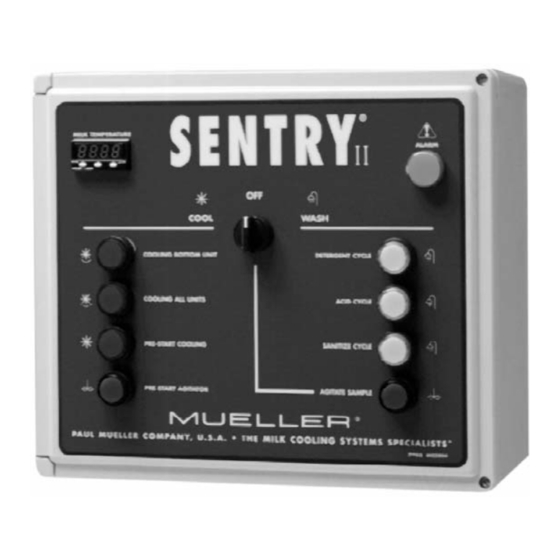
Figure 1 - Sentry II Control Cabinet and Milk Cooler Components A. Sentry II Control Box Pre-Start Switch/Indicator (Agitate) B. Alarm Indicator M. Water Works Box C. Detergent Switch/Indicator N. Hot Water Solenoid D. Acid Switch/Indicator O. Cold Water Solenoid E. -
Page 7: Section 2.0 - Installation
Floor Jack Cradle Block Block skids to ensure safety while removing the Self-Tapping Screws self-tapping screws from the bottom of each leg. Sentry II with Water Works Box Operating Instructions Effective April 1, 2000 Part No. 8823728 Revised November 10, 2003... -
Page 8: Site Requirements
Operation Manual specific to the refrigeration unit(s) being installed. NOTE: All wiring to be performed in accordance with the National Electrical Code and/or regulatory agency for the installation locality. All wiring that enters the Sentry II control box must be sealed with cord grips or liquid-tight conduit connectors. -
Page 9: Foundation Requirements
IMPORTANT NOTE: Mueller warrants to the original purchaser/user that the Mueller factory calibration of a Mueller milk cooler will not be affected (i.e. exceed the tolerances prescribed by the National Institute of Standards and Technology) by distortion or structural change for a period of five (5) years from the date of installation or sixty-six (66) months from the date of shipment from the Company factory, whichever occurs first. -
Page 10: Leveling The Milk Cooler
Side Mounted Levels Adjust milk cooler legs with a nylon strap wrench. Wood Cradle Block DFE0161 Floor Jack Sentry II with Water Works Box Operating Instructions Effective April 1, 2000 Part No. 8823728 Revised November 10, 2003... -
Page 11: Bulk Head Installations
If the milk cooler is bulkheaded through a wall, the wall must be free-standing and not load bearing against the milk cooler. Mueller offers an optional steel-formed structural support channel that may be installed in masonry walls to prevent the wall from bearing load on the milk cooler. Contact Mueller’s Sales Department for availability and pricing. -
Page 12: Milk Room Installations
1.125" rubber grommets, which provides a method to support the water/chemical fill hose inside of .75" PVC conduit. See Figure 7. Figure 7 - Milk Room Installations Sentry II with Water Works Box Operating Instructions Effective April 1, 2000 Part No. 8823728... -
Page 13: Agitator Assembly Installation
6. The optional agitator weather shield (Item 13) must be installed on all agitators that are located exterior of the milk room. Figure 8 - Agitator Installation Sentry II with Water Works Box Operating Instructions Effective April 1, 2000 Part No. 8823728... -
Page 14: Pump Assembly And Electric Drain Installation
12. Reattach the stainless steel cover plate and tighten all cord grips and liquid-tight conduit fittings. Figure 9 - Pump Assembly and Electric Drain Installation Sentry II with Water Works Box Operating Instructions Effective April 1, 2000 Part No. 8823728... -
Page 15: Instructions For Mounting The Sentry Ii Control Box Enclosures
2.13 Instructions for Mounting the Sentry II Control Box Enclosures 1. Install the Sentry II control box in a location where it is easily accessible for the operator and protected from excessive wash down. 2. Install the water works box in an area protected from freezing and within easy access to the chemical storage drums. -
Page 16: Chemical And Cleaning Cautions
POISON ▲ Inspect the milk cooler ladder hardware on a regular basis. Never climb a ladder which is in need of repair. Sentry II with Water Works Box Operating Instructions Effective April 1, 2000 Part No. 8823728 Revised November 10, 2003... -
Page 17: Manway Wash Tube Installation
Refer to Figure 11 for detailed installation procedures. Figure 11 - Manway Wash Tube Sentry II with Water Works Box Operating Instructions Effective April 1, 2000 Part No. 8823728... -
Page 18: Spray Dish Installation
See Figure 12. Figure 12 - Spray Dish Orientation Sentry II with Water Works Box Operating Instructions Effective April 1, 2000 Part No. 8823728... -
Page 19: Milk Cooler Vent Assembly Installation
Mueller Model “O,” “OE,” “OH,” and “OHF” milk coolers are designed for operation at normal atmospheric pressure only. -
Page 20: Section 3.0 - Electrical Wiring
Following the electrical schematics, insert the correct conductor into terminal connection “B” and remove the screwdriver, allowing the quick-connect terminal to close on the conductor. Sentry II with Water Works Box Operating Instructions Effective April 1, 2000 Part No. 8823728... -
Page 21: Figure 15—Electrical Schematic - Rear Junction Box
CONSTANTAN (-) THERMOCOUPLE (SILVER) CHASSIS GROUND COPPER (+) DRAIN VALVE (24 VAC) WASH PUMP (240 VAC) AGITATOR AGITATOR (240 VAC) (240 VAC) Sentry II with Water Works Box Operating Instructions Effective April 1, 2000 Part No. 8823728 Revised November 10, 2003... -
Page 22: Figure 16—Internal Conduit Raceways - Milk Cooler
POINT ELECTRICAL CONNECTION REAR ACCESS OPENING 1/2 CONDUIT FOR DRAIN & PUMP CORD (SIDE MOUNT) 1/2 CONDUIT FOR THRERMOCOUPLE WIRE ELEVATION DFE0042 Sentry II with Water Works Box Operating Instructions Effective April 1, 2000 Part No. 8823728 Revised November 10, 2003... -
Page 23: Figure 17—Electrical Schematic - Field Wiring (Enlarged Schematic Attached In Back)
Figure 17 - Electrical Schematic - Field Wiring (Enlarged Schematic Attached in Back) Sentry II with Water Works Box Operating Instructions Effective April 1, 2000 Part No. 8823728 Revised November 10, 2003... -
Page 24: Figure 18—Electrical Schematic - Factory Wiring (Enlarged Schematic Attached In Back)
Figure 18 - Electrical Schematic - Factory Wiring (Enlarged Schematic Attached in Back) Sentry II with Water Works Box Operating Instructions Effective April 1, 2000 Part No. 8823728 Revised November 10, 2003... -
Page 25: Figure 19—Relay And Switch Contact Positions (For Sentry Ii With Water Works Box)
Figure 19 - Relay and Switch Contact Positions (For Sentry II with Water Works Box) NOTE: CR1 RELAY COIL ENERGIZED WHEN SELECTOR SWITCH IS IN THE WASH POSITION ONLY. COM0 NEUTRAL 24 VAC 24 VAC X1 - 24 VAC NEUTRAL... -
Page 26: Plc Electrical Troubleshooting (Input And Output Data)
Acid Solenoid Not Used Not Used SERVICE NOTE: Inputs “X” are 24 VDC and outputs “Y0 - Y15” are 24 VAC. Sentry II with Water Works Box Operating Instructions Effective April 1, 2000 Part No. 8823728 Revised November 10, 2003... -
Page 27: Figure 20—Electrical Schematic - Plc (For Sentry Ii Models With Water Works Box)
Figure 20 - Electrical Schematic - PLC (For Sentry II Models with Water Works Box) BLACK L1C PLC CONTROLLER COM0 COM1 COM2 COM3 BLUE 20A BLUE 11N Sentry II with Water Works Box Operating Instructions Effective April 1, 2000 Part No. 8823728... -
Page 28: Figure 21—Electrical Schematic - Water Works Box
Figure 21 - Electrical Schematic - Water Works Box Sentry II with Water Works Box Operating Instructions Effective April 1, 2000 Part No. 8823728 Revised November 10, 2003... -
Page 29: Section 4.0 - Sentry Ii Temperature Control
SECTION 4.0 - SENTRY II TEMPERATURE CONTROL Sentry II Temperature Control and Thermocouple Sensor The Sentry II control uses an electronic temperature control with digital display and a Type “T” thermocouple sensor. The following installation and calibration procedures are very important to ensure accurate sensing of the milk temperature. -
Page 30: Sentry Ii Thermocouple Sensor Wiring
Cut and insulate the foil shield and drain wire of the thermocouple extension cable at the top-rear junction box. The drain wire should be grounded (one end only) at the Sentry II control cabinet. Route the thermocouple extension cable from the rear junction box to the wall-mounted Sentry II. -
Page 31: Important Thermocouple Splicing Information
Use non-metallic wire nuts, Mueller Part No. 8822361, to make all spliced thermocouple connections. If thermocouple extension cable is required, Mueller Part No. 8820166, connect the drain wire to the electrical ground at the Sentry II enclosure and cap and insulate the foil shield and drain wire at the opposite end. -
Page 32: Sentry Ii Temperature Control Lock And Unlock Features
Sentry II Temperature Control Lock and Unlock Features The temperature control is equipped with a locking feature to prevent unauthorized adjustments to the calibration, temperature set points, and unit of measure. Unlock - To unlock the temperature control for adjustment, press and hold the ▲ and ▼ keys (see Figure 25) simultaneously for two seconds. -
Page 33: Sentry Ii Temperature Control Set Point Adjustment
40°F (4.4°C) 41°F (5.0°C) 39°F (3.9°C) 43°F (6.0°C) 37°F (2.8°C) 41°F (5.0°C) 42°F (5.5°C) 40°F (4.4°C) 44°F (6.6°C) 38°F (3.3°C) Factory setting. Sentry II with Water Works Box Operating Instructions Effective April 1, 2000 Part No. 8823728 Revised November 10, 2003... -
Page 34: Sentry Ii Temperature Control Unit Of Measure (Fahrenheit Or Celsius)
The display will blink once when the keys are released, informing you that the control was successfully locked. See Section 4.6. Sentry II Temperature Control Unit of Measure (Fahrenheit or Celsius) 1. Unlock the temperature control as instructed in Section 4.6. -
Page 35: Determining Chemical Usage
SECTION 5.0 - CHEMICAL DOSING WITH SENTRY II WATER BOX Determining Chemical Usage The chemical usage will vary depending on the make and manufacturer, the amount of water required for each cycle, and the water quality. It is very important to have your Chemical Supplier test the water supply and determine the proper usage and concentrations of each specific chemical. -
Page 36: Determining Water Usage Requirements
Determining Water Usage Requirements The PLC in the Sentry II is supplied with a potentiometer that allows the volume of fill water to be adjusted for each specific installation. As the timer is turned clockwise to increase the volume of wash water, it automatically increases the electric drain time to ensure adequate drainage at the end of each cycle. -
Page 37: Determining Actual Water Usage
55.90 221.45 58.50 14.00 167.47 44.24 198.73 52.50 227.88 60.20 238.48 63.00 15.00 179.43 47.40 212.93 56.25 244.16 64.50 255.52 67.50 Sentry II with Water Works Box Operating Instructions Effective April 1, 2000 Part No. 8823728 Revised November 10, 2003... -
Page 38: Wash Cycle Timing Sequence
Wash Cycle Timing Sequence The Sentry II provides several programming options for the wash cycles. See Section 6 for detailed information. Chart 1 - Detergent Wash or Complete Wash NOTE: Fill and drain times are charted with the PLC potentiometer turned to the far counterclockwise position. -
Page 39: Chart 2-Acid Cycle Or Sanitize Cycle
Chart 2 - Acid Cycle or Sanitize Cycle NOTE: Fill and drain times are charted with the PLC potentiometer turned to the far counterclockwise position. See Section 5.3 and Figure 26. Sentry II with Water Works Box Operating Instructions Effective April 1, 2000 Part No. 8823728... -
Page 40: Section 6.0 - Sentry Ii Plc Programming
SECTION 6.0 - SENTRY II PLC PROGRAMMING Sentry II Programmable Features, Options, and Recommendations The Sentry II offers the following programming options, allowing the cooling and washing procedures to be customized for each specific installation: Programming Selectable Reference Feature Description and Recommendations... -
Page 41: Sentry Ii - Mta To Plc Programming Procedures
Sentry II - MTA to PLC Programming Procedures 1. Open the hinged door on the PLC. 2. Energize the power supply to the Sentry II Control before proceeding to Step 3. 3. Plug the MTA into the PLC. SAFETY ALERT: Be careful not to touch any terminals, power is applied! 4. - Page 42 Minute Delay 9. Press the ✚ key to increase or the – key to decrease the Bottom Unit Time Delay. Sentry II with Water Works Box Operating Instructions Effective April 1, 2000 Part No. 8823728 Revised November 10, 2003...
- Page 43 13. Press the ✚ key to display the current time delay setting: 0-120 Minutes. The MTA will display the current time delay selection: xx Minute Delay Sentry II with Water Works Box Operating Instructions Effective April 1, 2000 Part No. 8823728 Revised November 10, 2003...
- Page 44 17. Press the ▼ key, scrolling past the previous programmable selection, to the next option: Pre-Start Cooling. The MTA will display: ➞ Pre-Start Cool Sentry II with Water Works Box Operating Instructions Effective April 1, 2000 Part No. 8823728 Revised November 10, 2003...
- Page 45 28. Press the ✚ key to display the current settings: 3 Out of Every 30 Minutes or 3 Out of Every 18 Minutes. Sentry II with Water Works Box Operating Instructions Effective April 1, 2000 Sentry II with Water Works Box Operating Instructions Effective April 1, 2000 Part No.
- Page 46 36. Press the ✚ key to enter the new setting. 37. Press the key to enter the selection. 38. Press the ✚ key to return to the main menu. Sentry II with Water Works Box Operating Instructions Effective April 1, 2000 Part No. 8823728 Revised November 10, 2003...
- Page 47 – key to turn it Off. 47. Press the key to enter the selection. 48. Press the ✚ key to return to the main menu. Sentry II with Water Works Box Operating Instructions Effective April 1, 2000 Part No. 8823728 Revised November 10, 2003...
- Page 48 Cold. 57. Press the key to enter the selection. 58. Press the ✚ key to return to the main menu. Sentry II with Water Works Box Operating Instructions Effective April 1, 2000 Part No. 8823728 Revised November 10, 2003...
- Page 49 63. Press the ✚ key to return to the main menu. 64. Press the ▼ key to scroll to the next option: Service Contact. 65. Press the ✚ key to select Paul Mueller Company. 66. Consecutively press the ▼ key, scrolling...
-
Page 50: Sentry Ii Service Reference Form, Programmable Features
❏ 45 minutes Delayed Start - Complete Wash Sentry Information: Milk Cooler Information: Part Number/Model: Part Number/Model: Serial Number: Serial Number: Comments: Sentry II with Water Works Box Operating Instructions Effective April 1, 2000 Part No. 8823728 Revised November 10, 2003... -
Page 51: Section 7.0 - Operating Instructions
The Sentry II control system is designed for easy, touch-of-a-button operation with simple visual notification of each operational mode with bright, illuminated indicators. Please locate the enclosed plastic laminated reference chart, Part No. 8823727, near the Sentry II control. This will provide unfamiliar operators with a quick reference to the basic operation and features of the Sentry II control system. -
Page 52: Cooling All Units Switch
2. This feature blends the warm incoming milk at the onset of the second, third, or fourth milkings. 3. To cancel Pre-Start Agitator press the switch a second time. Sentry II with Water Works Box Operating Instructions Effective April 1, 2000 Part No. -
Page 53: Detergent Cycle Switch
The agitator(s) will operate for the programmed period of 2, 5, or 10 minutes, and shut off automatically. See Sections 6.1 and 6.2 (31-37). 2. To cancel Agitate Sample press the switch a second time. Sentry II with Water Works Box Operating Instructions Effective April 1, 2000 Part No. 8823728... -
Page 54: Alarm Lamp
2. To access and activate this switch, turn the power off to the Sentry II control box, open the door and move this switch to the Manual position. Close the door, turn selector switch to the Cool position, and reapply power. -
Page 55: Section 8.0 - Weights And Dimensions
Actual calibration capacity may exceed certified capacity. Minimum and maximum clearance under the milk cooler with standard adjustable legs. Approximate weight measured in pounds (includes agitator(s), pump assembly, and controls). Sentry II with Water Works Box Operating Instructions Effective April 1, 2000 Part No. 8823728... -
Page 56: Metric Weights And Dimensions
Actual calibration capacity may exceed certified capacity Minimum and maximum clearance under the milk cooler with standard adjustable legs. Approximate weight measured in kilograms (includes agitator(s), pump assembly, and controls). Sentry II with Water Works Box Operating Instructions Effective April 1, 2000 Part No. 8823728... -
Page 57: Section 9.0 - Sentry Ii Equipment Markings
8820248 Label No. 8822584, Pump Motor - Wire Marker PUMP MOTOR 8822584 Label No. 8802375, Agitator(s) - Wire Marker AGITATOR(S) 8802375 Sentry II with Water Works Box Operating Instructions Effective April 1, 2000 Part No. 8823728 Revised November 10, 2003... -
Page 58: Label No. 3791, Hot - Water Valve Marker
BEFORE SERVICING. 0001 8823013 9.12 Part No. 8822225, CE Data Tag (U.K. Models Only) ® Paul Mueller Company • 1600 W. Phelps • P.O. Box 828 • Springfield, Missouri 65801-0828, U.S.A. Year of Construction Model Number Serial Number Noise Level... -
Page 59: Label No. 8801150, Warning - Disconnect Power Before Servicing
Improper installation could result in claims by the buyer or seller of the milk against the party making the installation. 6911 30612 Sentry II with Water Works Box Operating Instructions Effective April 1, 2000 Part No. 8823728 Revised November 10, 2003... -
Page 60: Label No. 8820454, Dry Nitrogen Holding Charge
N.B. La presente norma se ha consolidado hasta el 30 de septiembre de 1992. 8805299 9.18 Label No. 30737, Bottom Temp-Plate BOTTOM TEMP-PLATE ® 30737 Sentry II with Water Works Box Operating Instructions Effective April 1, 2000 Part No. 8823728 Revised November 10, 2003... -
Page 61: Label No. 8822972, Transformer Wiring
(240 VAC) L1 Main Power (240 VAC) L2 Main Power (240 VAC) 0004 8823729 9.22 Label No. 8820409, Mueller Name Tag 8820409 Sentry II with Water Works Box Operating Instructions Effective April 1, 2000 Part No. 8823728 Revised November 10, 2003... -
Page 62: Label No. 8823369, Programmable Controller Name Tag
Note: The cooling performance specified above is based upon use of the largest condensing unit recommended for this cooler. Smaller condensing units may be used, but at reduced fill rates. Contact your Mueller dealer for assistance in condensing unit sizing. -
Page 63: Label No. 30166, Caution - Vent Must Be Over Milk Inlet
(OE MODELS ONLY) AGITATOR DRAIN VALVE THERMOCOUPLE AGITATOR PUMP MOTOR (SENTRY MODELS ONLY) 0003 8823146 (240 VAC) (240 VAC) (24 VAC) (240 VAC) Sentry II with Water Works Box Operating Instructions Effective April 1, 2000 Part No. 8823728 Revised November 10, 2003... -
Page 64: Section 10.0 - Safety
Note: See all safety, warning, and caution labels displayed in Sections 2.15, 5.2, and 10. 10.1 General The Mueller milk cooler and Sentry II control system should be operated by qualified personal who are familiar with the equipment and instructions. Improper handling, operation, or service of the equipment, cleaning chemicals, and/or electricity can create a health hazard and possible non-warranted damage to the equipment. -
Page 65: Section 11.0 - Disposal
The milk cooler’s basic components consist of steel, copper, rubber, and plastics which may be separated and recycled. The “CFC-Free” foam insulation should be disposed of according to local environmental regulations and agencies. Sentry II with Water Works Box Operating Instructions Effective April 1, 2000 Part No. 8823728... - Page 66 ® Sentry II Service Reference Form Programmable Features Please complete for future service reference: Mueller Authorized Dealer: End User/Owner: Name: Name: Address: Address: Phone: Phone: Contact: Contact: PROGRAM OPTIONS Description Options and Selection ❏ Bottom Unit(s) Cooling Delay 0-120 minutes minutes ❏...
- Page 67 ELECTRICAL SCHEMATIC - FIELD WIRING SENTRY II WALL-MOUNT WATER WORKS 03/28/00 - 8823608 POWER SUPPLY FOR WALL MOUNT SENTRY II 230-200/60/50/1 LOW VOLTAGE 24 VAC 240 VAC 240 VAC W/ WALL MOUNT WATER BOX CUSTOMER SUPPLIED PUMP MOTOR 15 AMP FUSED DISCONNECT SENTRY II .75HP = 8.4 AMPACITY...
- Page 68 BLUE 43 DOOR NOTES: 1. REFERENCE DRAWING NO. 8001889D FOR SENTRY II SCHEMATIC WIRING DIAGRAM. CABINET 2. ALL ENFORCED ELECTRICAL CODES MUST BE FOLLOWED DURING INSTALLATION, SERVICE, AND/OR OPERATION OF THIS EQUIPMENT. 3. DIAGRAM SHOWN WITH OPTIONAL 195V TRANSFORMER AND 240V TRANSFORMER CONNECTED.
- Page 69 ® P.O. Box 828 • Springfield, Missouri 65801-0828, U.S.A. Phone: (417) 831-3000 • 1-800-MUELLER • Fax: 1-800-436-2466 www.muel.com • E-mail: dairyfarm@muel.com International Inquiries - Fax: (417) 831-6906 • E-mail: international@muel.com (11/03) 8823728...
Need help?
Do you have a question about the SENTRY II and is the answer not in the manual?
Questions and answers